Nissan Ariya: Removal and Installation
Front Coil Spring and Strut Nissan Ariya 2026
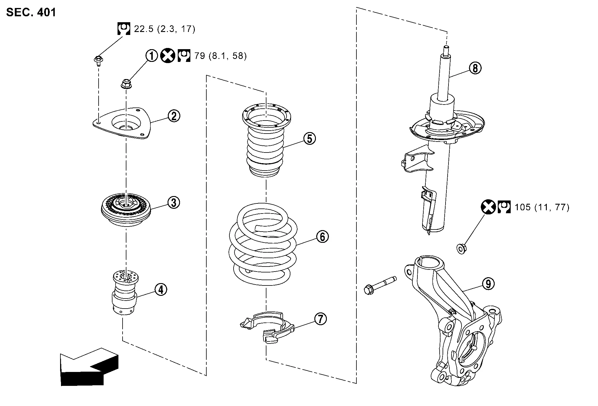
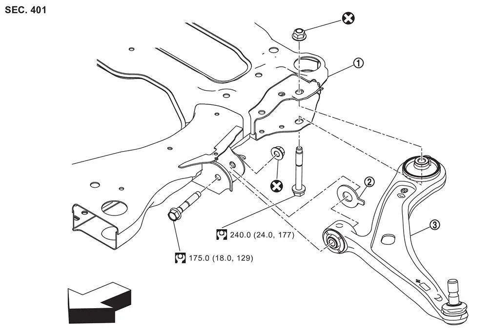
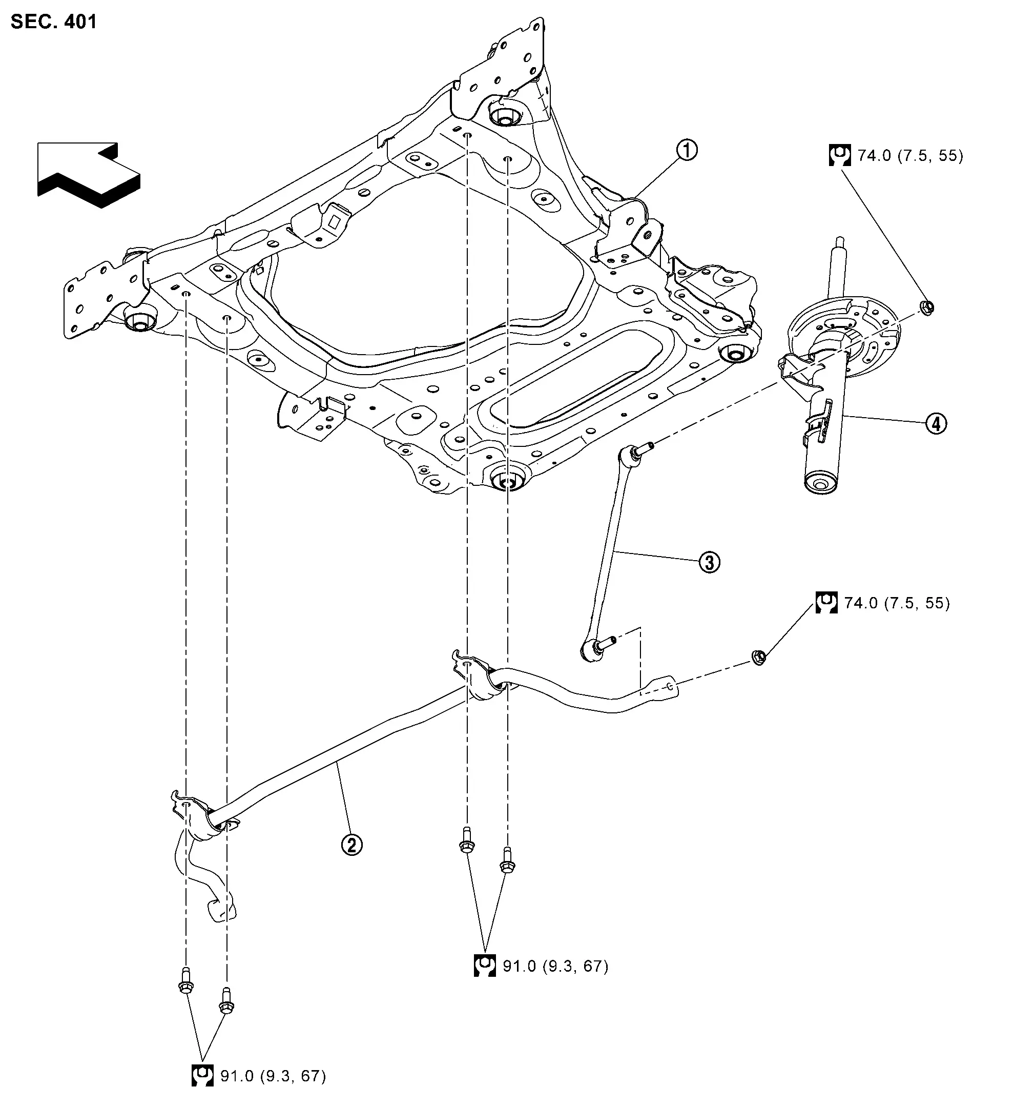
FRONT COIL SPRING AND STRUT : Exploded View
 |
Piston rod lock nut |  |
Mounting insulator |  |
Mounting bearing |
 |
Bound bumper |  |
Upper rubber seat |  |
Coil spring |
 |
Lower rubber seat |  |
Strut |  |
Steering knuckle |
 |
: Nissan Ariya Vehicle front | ||||
 |
: N·m (kg-m, ft-lb) | ||||
 |
: Always replace after every disassembly. | ||||
FRONT COIL SPRING AND STRUT : Removal & Installation
REMOVAL
Remove cowl top cover. Refer to Removal and Installation.
Remove tires. Refer to ROAD WHEEL TIRE : Removal and Installation.
Remove wheel hub lock nut. Refer to FRONT WHEEL HUB AND KNUCKLE : Removal and Installation.
Remove front brake hose lock prate. Refer to FRONT BRAKE PIPING : Removal and Installation.
Remove front wheel sensor. Refer to FRONT WHEEL SENSOR : Removal and Installation.
Remove cylinder body from torque member and hang cylinder body with wire while preventing brake hose from being stretched.
CAUTION:
Never depress brake pedal while brake caliper is removed.
Remove disc rotor.
Remove steering outer socket. Refer to STEERING GEAR AND LINKAGE: Exploded view.
Remove transverse link. Refer to TRANSVERSE LINK: Removal and Installation.
Separate stabilizer connecting rod from strut assembly.
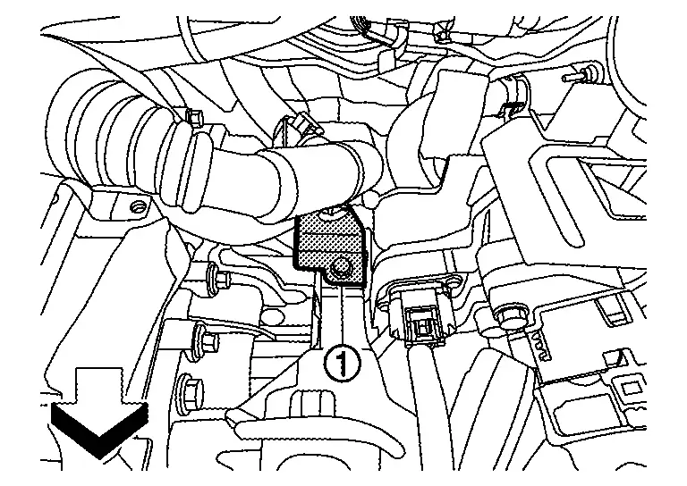
Remove grommet in front of strut assembly mounting bolt.
|
: Nissan Ariya Vehicle front |
Remove steering knuckle and strut assembly from vehicle.
CAUTION:
-
Never place drive shaft joint at an extreme angle.
-
Be careful not to overextend slide joint of drive shaft.
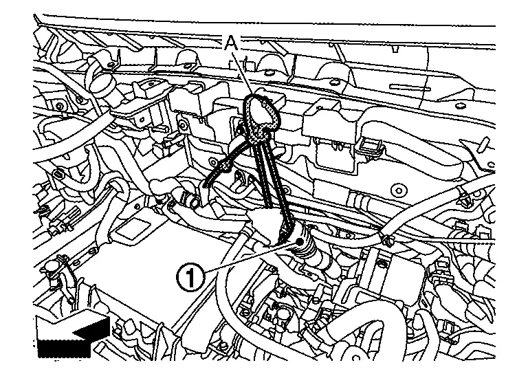
Separate the connection of strut assembly and steering knuckle as follows.
CAUTION:
Be sure to keep the following procedure because steering knuckle may be damaged when the gap of steering knuckle is enlarged too much.
-
Remove strut connecting bolts from steering knuckle.
-
Measure the gap (A) of the steering knuckle and then put mark
 of enlarged limit (B) on the chisel.
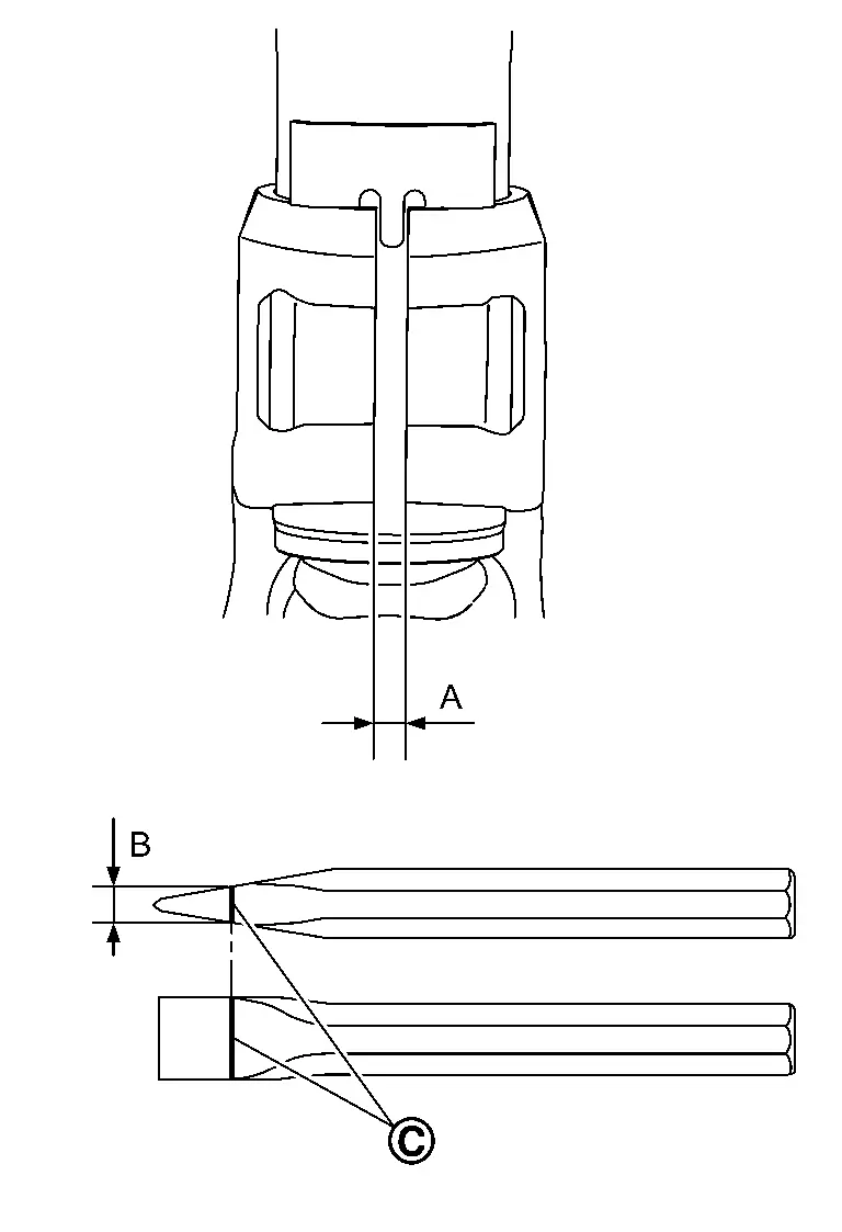
Enlarged limit (B) = Gap (A) + 2.5 mm (0.098 in)  NOTE:
NOTE:
Specified gap : 6.9 ± 0.5 mm (0.272 ± 0.02 in) -
Enlarge the gap of the steering knuckle with the chisel (A) (commercial service tool) not to surpass a limit as shown in the figure.
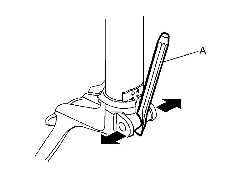
CAUTION:
-
Never enlarge the gap more than 2.5mm (0.098in).
-
Be careful not to damage the projection
 and strut assembly
  with the chisel.
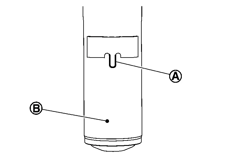
-
-
Separate the connection of strut assembly and steering knuckle.
INSTALLATION
Note the followings, and install in the reverse order of removal.
Strut Assembly
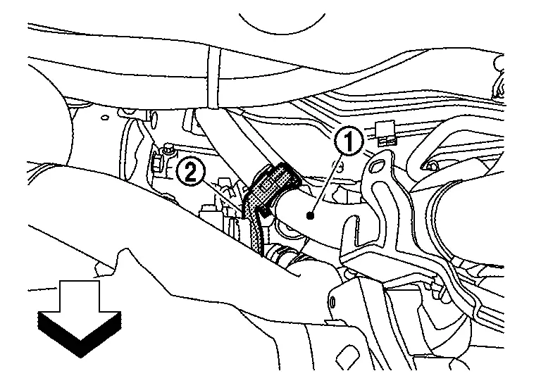
When installing strut assembly to the vehicle, set the mounting insulator to the direction shown in the figure.
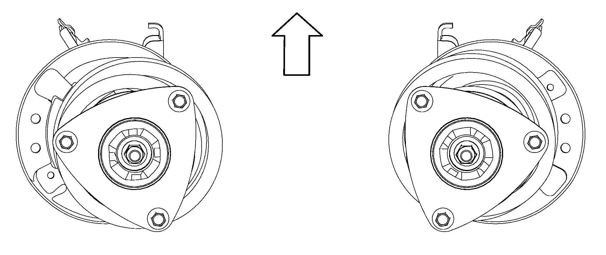
|
: Nissan Ariya Vehicle front |
Strut Assembly and Steering Knuckle Connection
CAUTION:
Be sure to remove lubricants with brake cleaner if lubricant is used to separate the connection of strut assembly and steering knuckle.
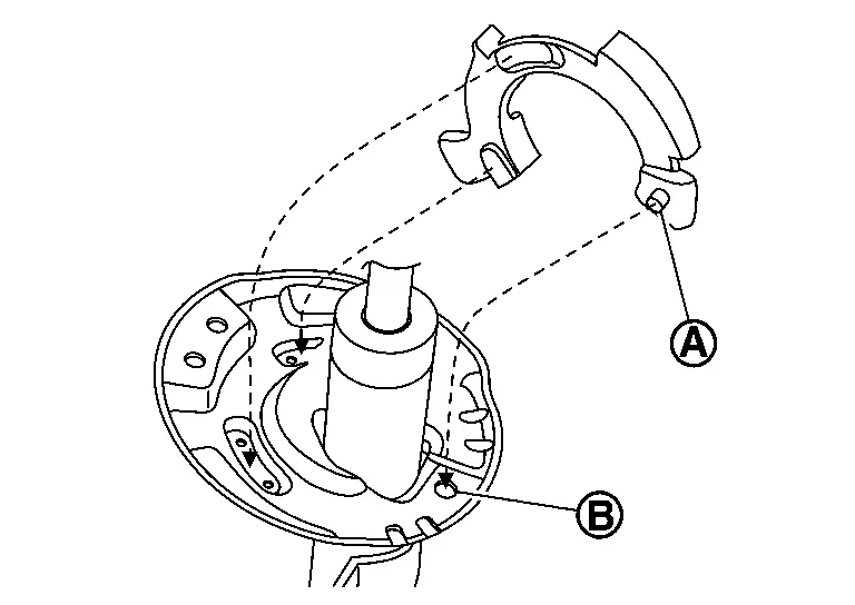
Install the steering knuckle to strut assembly as follows.
-
Align the gap
of steering knuckle to the projection part of strut.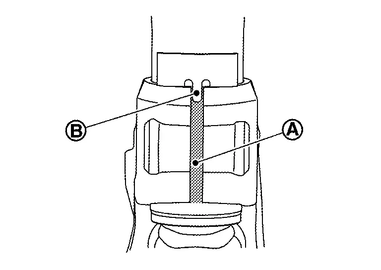
-
Tighten mounting bolt of steering knuckle
until contacts stopper bracket end face while pushing it up with suitable jack.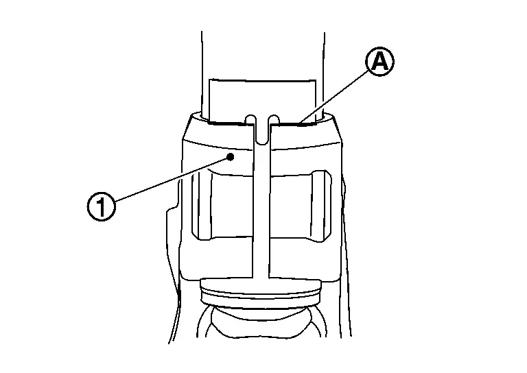
CAUTION:
Check the stable condition when using a jack.
-
When installing suspension component parts, the final tightening of rubber bush is performed while Nissan Ariya vehicle is under unladen conditions with tires on level ground.
-
Perform inspection after installation. Refer to FRONT COIL SPRING AND STRUT: Inspection.
-
After replacing strut, always follow the disposal procedure to discard the strut. Refer to FRONT COIL SPRING AND STRUT: Disposal.
FRONT COIL SPRING AND STRUT : Disassembly & Assembly
DISASSEMBLY
CAUTION:
Never damage strut assembly piston rod when removing components from strut assembly.
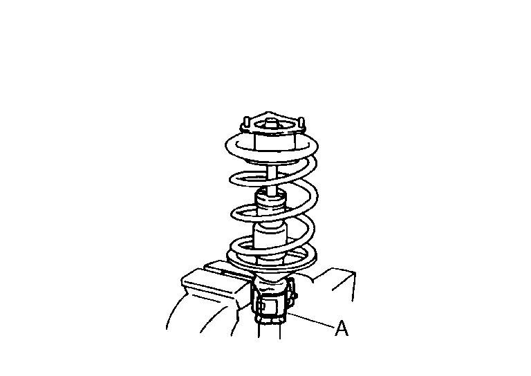
Install strut attachment (A) (SST: ST35652000) to strut assembly and secure it in a vise.
CAUTION:
When installing the strut attachment to strut assembly, wrap a shop cloth around strut to protect from damage.
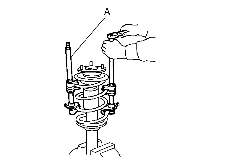
Using a spring compressor (A) (commercial service tool), compress coil spring between spring upper seat and lower seat (strut assembly) until coil spring with a spring compressor is free.
CAUTION:
Be sure the spring compressor is securely attached to coil spring before compressing it.
Check coil spring with spring compressor between spring upper seat and lower seat (strut assembly) is free. Remove piston rod lock nut while securing the piston rod tip not to turn piston rod.
Remove mounting insulator, mounting bearing upper rubber seat and bound bumper from strut.
After removing coil spring, gradually release the spring compressor (commercial service tool).
CAUTION:
Loosen while making sure that coil spring attachment position does not move.
Remove lower rubber seat.
Remove strut attachment (A) (SST: ST35652000) from strut.
Perform inspection after disassembly. Refer to Inspection.
ASSEMBLY
CAUTION:
Never damage strut assembly piston rod when installing components to strut assembly.
Install strut attachment (SST: ST35652000) to strut and secure it in a vise.
CAUTION:
When installing the strut attachment to strut assembly, wrap a shop cloth around strut to protect from damage.
Align protrusion at bottom of lower rubber seat with hole in the strut and then install lower rubber seat.
Compress coil spring using the spring compressor (commercial service tool), and install it to strut assembly.
CAUTION:
-
Be sure the spring compressor is securely attached to coil spring, before compressing coil spring.
-
Align the lower end of coil spring
with lower rubber seat as shown in the figure.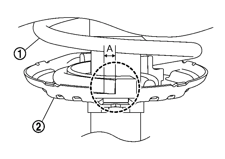
Dimension (A) : 5 mm (0.20 in) or less. -
Set coil spring by aligning paint marks with the position from the bottom end of the coil spring as shown in the figure.
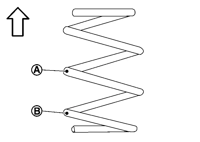
: Nissan Ariya Vehicle upper side : 2.25 turns : 1.25 turns
Set bound bumper to piston rod of strut.
Install mounting bearing and upper rubber seat to strut.
CAUTION:
-
Never apply oils, such as grease, when installing the mounting bearing and upper rubber seat.
-
When assembling the mounting bearing
and the upper rubber seat ,ensure that there is no gap between the mount bearing upper rubber seat and the strut part .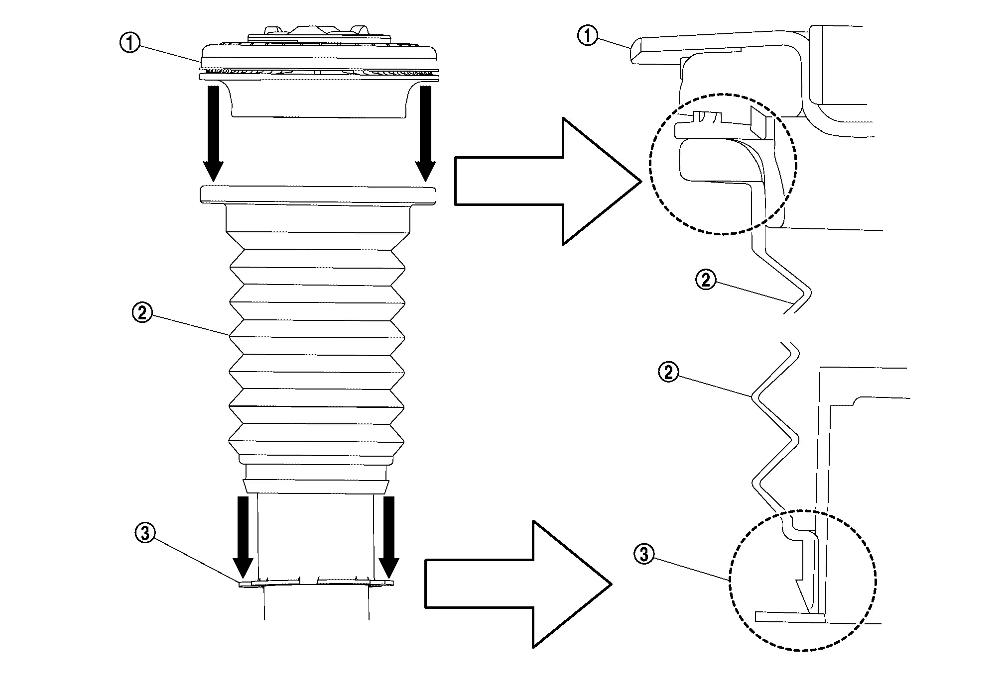
Set the mounting insulator to the direction shown in the figure, and then install the mounting insulator and the upper rubber seat with the mounting bearing to the strut.
|
: Nissan Ariya Vehicle front |
CAUTION:
Align the upper end of coil spring with upper rubber seat as shown in the figure.
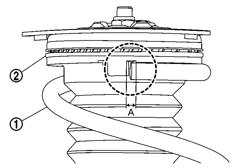
| Dimension (A) | : 5 mm (0.20 in) or less |
Secure piston rod tip to prevent piston rod from turning, then tighten piston rod lock nut to the specified tightening torque.
CAUTION:
Never reuse piston rod lock nut.
Gradually release the spring compressor (A) (commercial service tool), and remove coil spring.
CAUTION:
Loosen while making sure coil spring attachment position does not move.
Remove the strut attachment (A) (SST: ST35652000) from strut.
FRONT COIL SPRING AND STRUT : Inspection
INSPECTION AFTER DISASSEMBLY
Strut
Check the following items, and replace the parts if necessary.
-
Strut for deformation, cracks or damage
-
Piston rod for damage, uneven wear or distortion
-
Oil leakage
Strut Mounting Insulator, Bound Bumper, Upper Rubber Seat and Lower Rubber Seat
Check strut mounting insulator, bound bumper, upper rubber seat and lower rubber seat for cracks, wear or damage, and replace the parts if necessary.
Coil Spring
Check coil spring for cracks, wear or damage and replace the parts if necessary.
INSPECTION AFTER INSTALLATION
-
Check wheel sensor harness for proper connector. Refer to FRONT WHEEL SENSOR : Exploded View.
-
Check wheel alignment. Refer to WHEEL ALIGNMENT : Inspection.
-
Adjust neutral position of steering angle sensor. Refer to Work Procedure.
FRONT COIL SPRING AND STRUT : Disposal
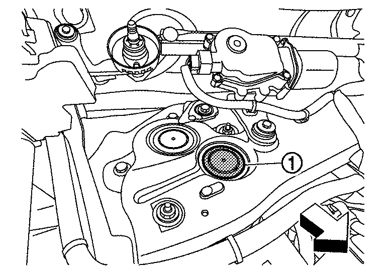
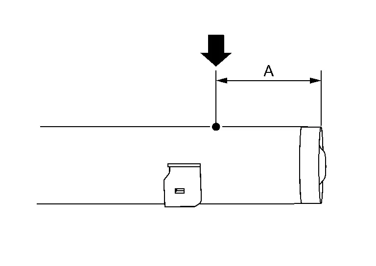
Set strut assembly horizontally to the ground with the piston rod fully extracted.
Drill 2 – 3 mm (0.08 – 0.12 in) hole at the position ( ) from top as shown in the figure to release gas gradually.
CAUTION:
-
Wear eye protection (safety glasses).
-
Wear gloves.
-
Be careful with metal chips or oil blown out by the compressed gas inside.
NOTE:
-
Drill vertically in this direction show by arrow(
 ).
). -
Drill directly to the outer tube avoiding brackets.
-
The gas is clear, colorless, odorless, and harmless.
| Dimension A | : 20 – 30 mm (0.79 – 1.18 in) |
Drain oil from drain hole by moving the piston rod several times.
CAUTION:
Dispose of drained oil according to the law and local regulations.
Transverse Link Nissan Ariya
TRANSVERSE LINK : Exploded View
|
Front suspension member | |
Stopper | |
Transverse link |
|
: Nissan Ariya Vehicle front | ||||
|
: N·m (kg-m, ft-lb) | ||||
|
: Always replace after every disassembly. | ||||
TRANSVERSE LINK : Removal & Installation
REMOVAL
Remove protector of water tube for battery.
Remove transverse link mounting bolts and nuts , and then remove transverse link from suspension member.
Remove transverse link from steering knuckle. Refer to Exploded view.
Perform inspection after removal. Refer to Inspection.
INSTALLATION
Note the following, and install in the reverse order of removal.
-
Never reuse transverse link mounting nut.
-
Perform final tightening of bolts and nuts at installation position of rubber bushing to the Nissan Ariya vehicle, under unladen conditions with tires on level ground.
-
Perform inspection after installation. Refer to Inspection.
TRANSVERSE LINK : Inspection
INSPECTION AFTER REMOVAL
Visual Inspection
Check the following items, and replace the parts if necessary.
-
Transverse link for deformation, cracks or damage.
-
Bushing for complete separation. (If completely separated, inner metal can be pulled out from transverse link.)
-
Ball joint boot for cracks or other damage, and also for grease leakage.
Ball Joint Check
Move the ball stud by hand and check that it moves smoothly without catching.
Swing Torque
CAUTION:
Move ball stud at least ten times by hand to check for smooth movement.
-
Hook a spring balance (A) at cutout on ball stud and pull it. When ball stud begins moving, measure spring balance value. The specified value is as follows;
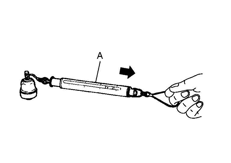
Specified Value Swing torque : BALL JOINT : Service Data Measurement value of spring balance (cutout on ball stud) : BALL JOINT : Service Data -
If swing torque exceeds specified range, replace transverse link assembly due to disassembly prohibited.
Axial end play
-
Move ball stud at least ten times by hand to check for smooth movement.
-
Move tip of ball stud in axial direction to check for looseness.
-
If there is axial end play, replace transverse link assembly.
-
Move the ball stud by hand and check that it moves smoothly without catching.
INSPECTION AFTER INSTALLATION
Check wheel sensor harness for proper connection. Refer to FRONT WHEEL SENSOR : Exploded View.
Check wheel alignment. Refer to WHEEL ALIGNMENT : Inspection.
Adjust neutral position of steering angle sensor. Refer to Work Procedure.
Front Stabilizer Nissan Ariya SUV
FRONT STABILIZER : Exploded View
|
Front suspension member | |
Stabilizer bar assembly | |
Stabilizer connecting rod |
|
Strut | ||||
|
: Nissan Ariya Vehicle front | ||||
|
: N·m (kg-m, ft-lb) | ||||
FRONT STABILIZER : Removal & Installation
REMOVAL
Remove tires. Refer to Removal and Installation.
Remove motor room under cover.
Remove stabilizer connecting rod. Refer to Exploded view.
Remove mounting bolts and the remove stabilizer assembly from suspension member.
Perform inspection after removal. Refer to Inspection.
INSTALLATION
Note the following, and install in the reverse order of removal.
-
When installing the stabilizer clamp mounting bolts, tighten in numerical order.
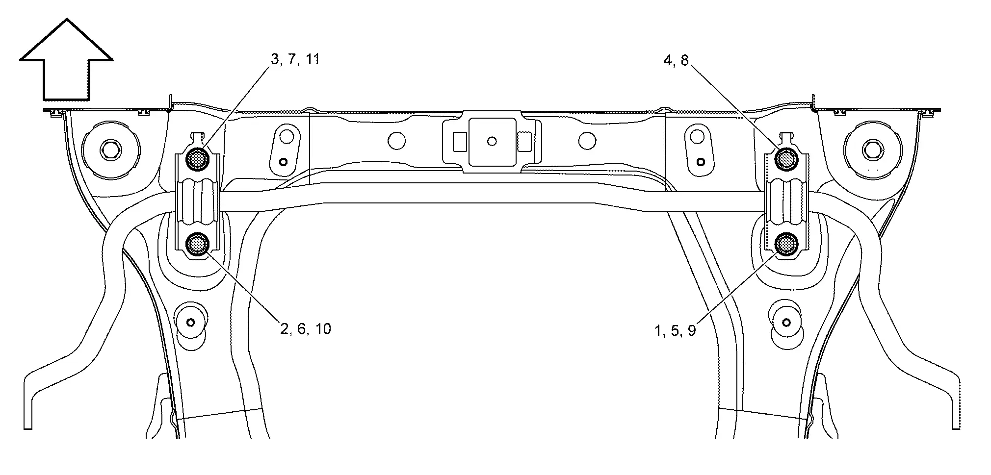
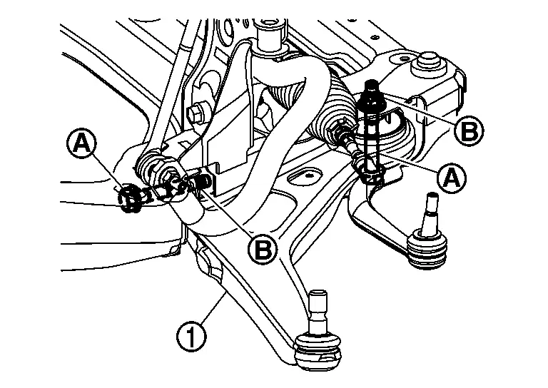
Temporary tightening (by hand) : 1 – 3 Temporary tightening (by tool) : 4→7 Final tightening (Specified torque) : 8→11 : Nissan Ariya Vehicle front -
To install stabilizer connecting rod
, tighten the mounting nut with the hexagonal part (A) on the stabilizer connecting rod side fixed.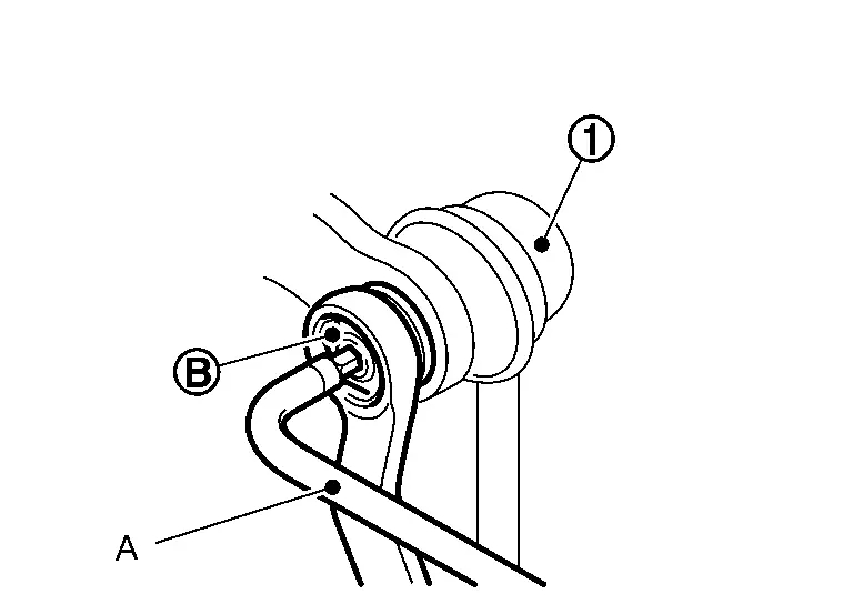
-
Preform inspection after installation. Refer to Inspection.
FRONT STABILIZER : Inspection
INSPECTION AFTER REMOVAL
Check stabilizer bar, stabilizer connecting rod, stabilizer bushing and stabilizer clamp for deformation, cracks or damage. Replace it if necessary.
INSPECTION AFTER INSTALLATION
Check wheel alignment. Refer to WHEEL ALIGNMENT : Inspection.
Adjust neutral position of steering angle sensor. Refer to Work Procedure.
Front Suspension Member Nissan Ariya SUV
FRONT SUSPENSION MEMBER : Exploded View
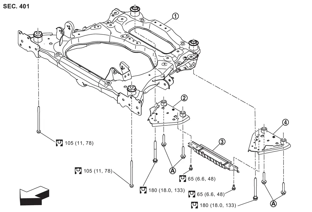
|
Front suspension member | |
Front member stay (Right side) | |
Reinforcement |
|
Front member stay (Left side) | ||||
|
Comply with the assembly procedure when tightening. Refer to Removal and Installation (For 66 KWH) and Removal and Installation (For 91 KWH). | ||||
|
: Nissan Ariya Vehicle front | ||||
|
: N·m (kg-m, ft-lb) | ||||
FRONT SUSPENSION MEMBER : Removal & Installation
DANGER: Because hybrid vehicles and electric vehicles contain a high voltage battery, there is a risk of electric shock, electric leakage, or similar accidents if the Nissan Ariya vehicle is handled incorrectly. Be sure to follow the correct work procedures when performing inspection and maintenance.
WARNING:
-
Be sure to remove the service plug in order to shut off the high voltage circuits before performing inspection or maintenance of high voltage system harnesses and parts.
-
Be sure to put the removed service plug in pocket and carry it or store it in a tool box or other container so that another person does not accidentally connect it while work is in progress.
-
Be sure to put on insulating protective gear before beginning work on the high voltage system.
-
Clearly identify the persons responsible for high voltage work and ensure that other persons do not touch the Nissan Ariya vehicle. When not working, cover high voltage components with an anti-static cover sheet or similar item to prevent contact with other persons.
-
Refer to PRECAUTIONS FOR HIGH VOLTAGE : Precautions.
CAUTION:
There is the possibility of a malfunction occurring if the vehicle is changed to READY status while the service plug is removed. Therefore do not change the Nissan Ariya vehicle to READY status unless instructed to do so in the Service Manual.
NOTE:
Open charge port lid before removing 12 V minus terminal.
REMOVAL
WARNING:
Prepare for work on the high-voltage system. Refer to HOW TO DISCONNECT HIGH VOLTAGE : Precautions.
-
Disconnect high voltage circuit. Refer to HOW TO DISCONNECT HIGH VOLTAGE : Precautions.
-
Check voltage of high voltage circuit. Refer to CHECK VOLTAGE IN HIGH VOLTAGE CIRCUIT : Precautions.
Remove minus terminal of 12 V battery. Refer to 12 V BATTERY : Removal and Installation.
Remove tires. Refer to Removal and Installation.
Remove front under cover . Refer to Front under Cover : Removal and Installation.
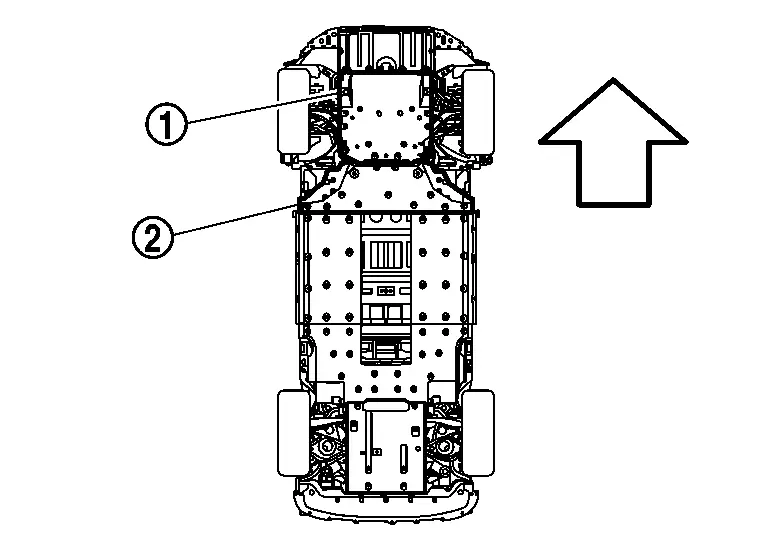
|
: Nissan Ariya Vehicle front |
|
: Li-ion battery under cover (front) |
Remove Li-ion battery under cover (front) . Refer to Removal and Installation (For 66 KWH) and Removal and Installation (For 91 KWH).
|
: Nissan Ariya Vehicle front |
|
: Front under cover |
Drain coolant of Li-ion battery and high voltage system. Refer to COOLANT : Draining.
Drain oil from reducer. Refer to REDUCTION GEAR OIL : Draining.
Discharge A/C refrigerant gas. Refer to Recycle Refrigerant.
Remove right and left front fender protectors. Refer to Removal and Installation.
Remove right and left stabilizer connecting rods. Refer to Removal and Installation.
Remove right and left drive shafts. Refer to FRONT DRIVE SHAFT : Removal and Installation.
Remove high voltage supply unit.
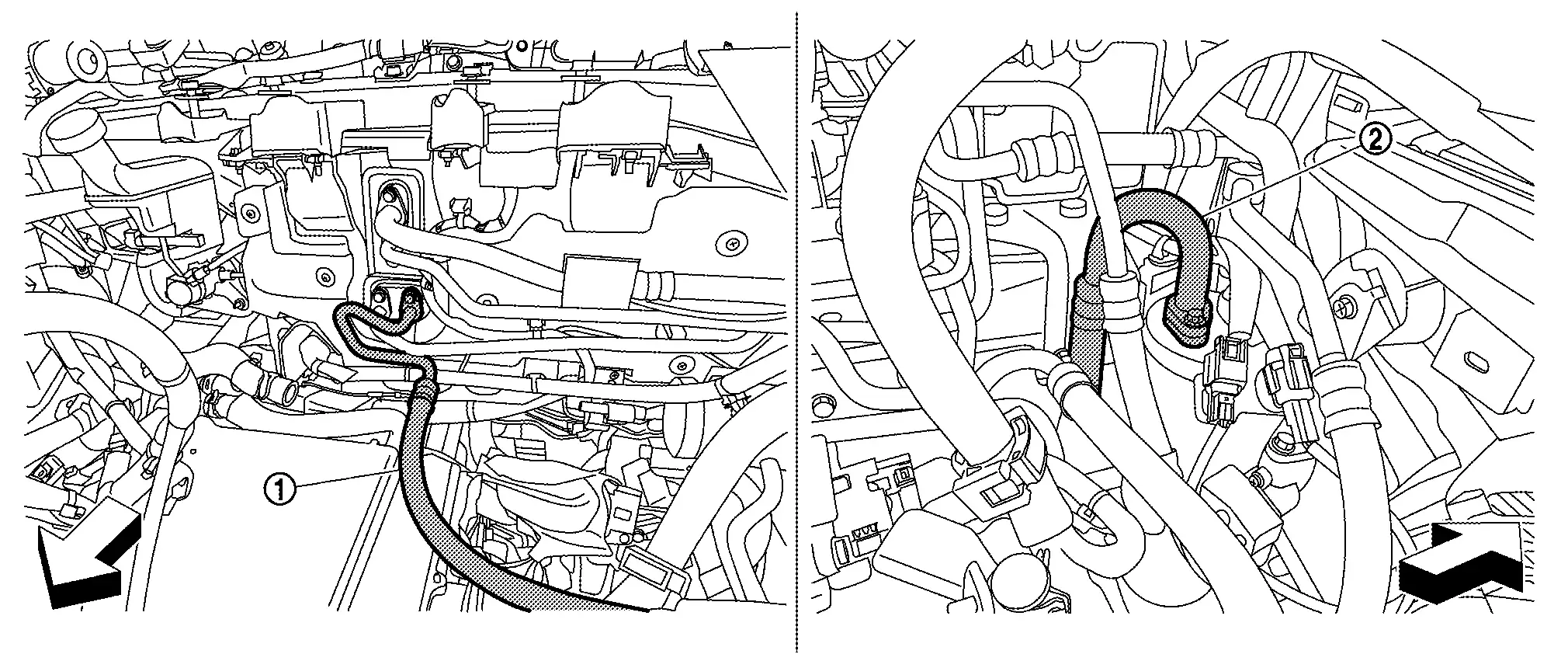
Remove A/C pipe and A/C flexible hose .
|
: Nissan Ariya Vehicle front |
Remove bus bar cover .
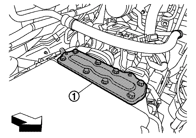
|
: Nissan Ariya Vehicle front |
Remove bus bar mounting bolts and high voltage harness fixing bolts .
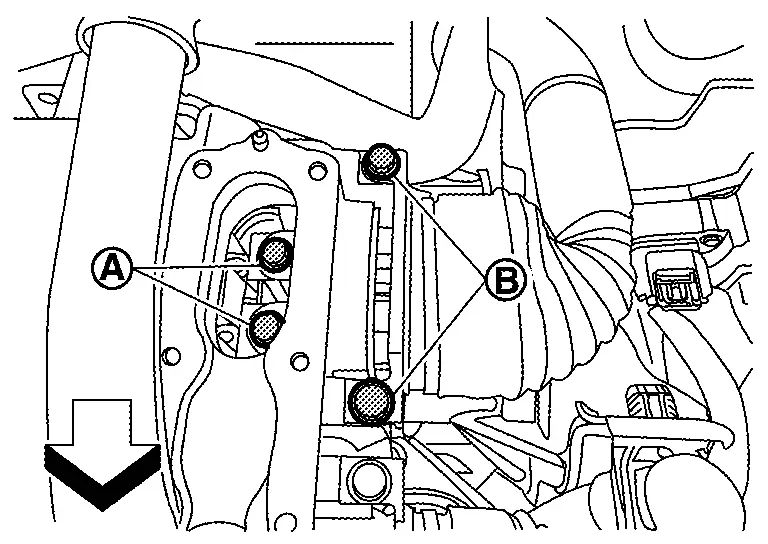
|
: Nissan Ariya Vehicle front |
Cover High voltage area.
Remove high voltage harness mounting bracket from reduction gear.
|
: Nissan Ariya Vehicle front |
Remove high voltage harness from bracket .
|
: Nissan Ariya Vehicle front |
Remove mounting bolts and the remove reinforcement .
|
: Nissan Ariya Vehicle front |
Disconnect high voltage harness from Li-ion battery and the remove bracket from Nissan Ariya vehicle.
|
: Nissan Ariya Vehicle front |
Cover high voltage area.
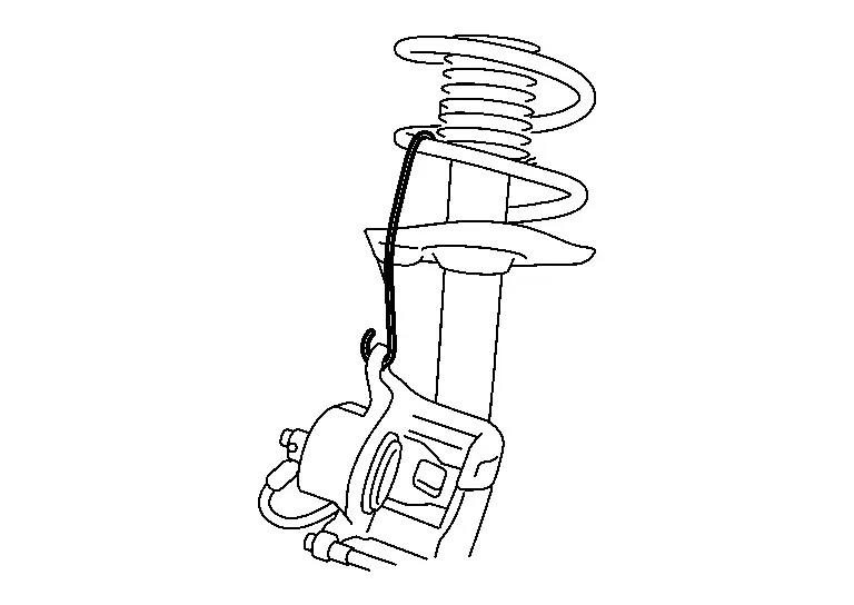
Hold high voltage harness to Nissan Ariya vehicle side with rope (A).
|
: Nissan Ariya Vehicle front |
Remove vehicle harness and harness clips.
-
Reduction gear (Upper side)
-
Traction motor (front and rear)
-
In-Nissan Ariya vehicle charger
-
Water pump for Li-ion battery
-
Water pump for high voltage system cooling
-
Power steering motor
Remove ground to body.
|
: Nissan Ariya Vehicle front |
 |
: Nissan Ariya Vehicle right side |
 |
: Nissan Ariya Vehicle left side |
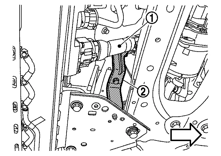
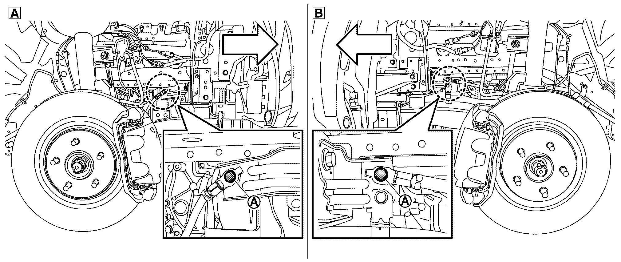
Remove water hose
-
Vehicle right side: Remove water hose
from water pump for Li-ion battery.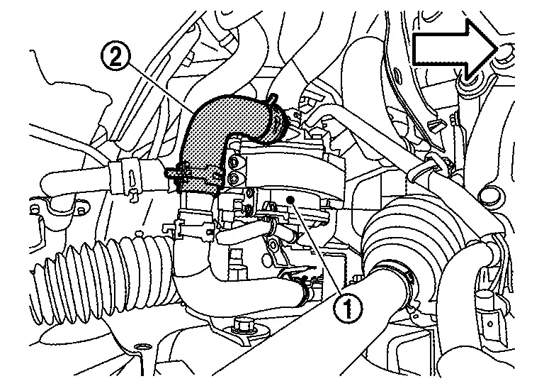
: Nissan Ariya Vehicle front -
Vehicle left side: Remove water hose
from water pump for high voltage cooling system.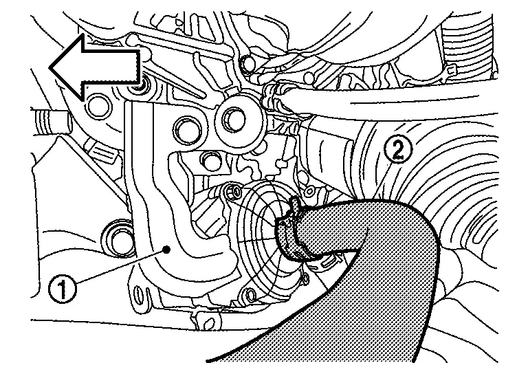
: Nissan Ariya Vehicle front -
Vehicle left side: Remove water hose
.
: Nissan Ariya Vehicle front
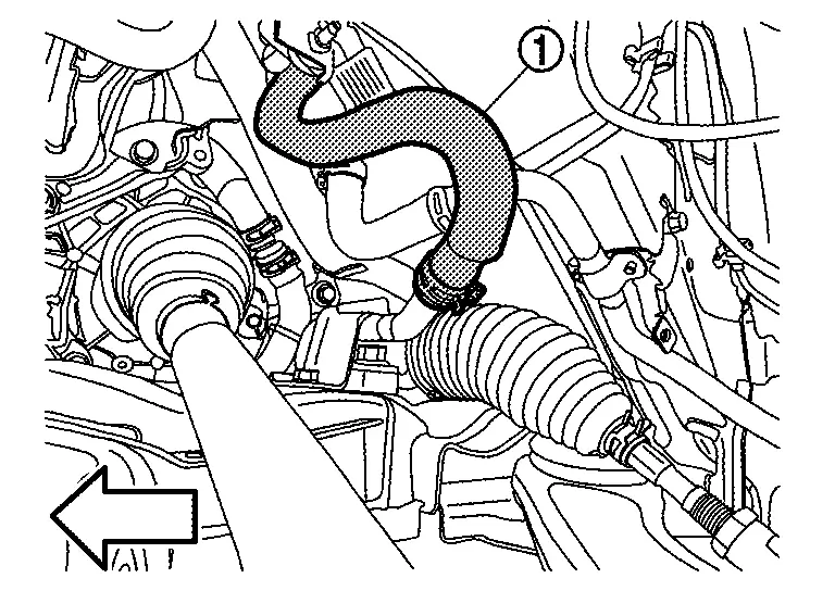
Remove joint of steering shaft lower.
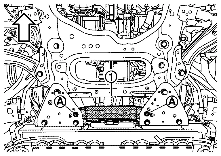
Remove under cover brackets .
|
: Nissan Ariya Vehicle front |
NOTE:
Before removing under cover brackets from suspension member, put align marks.
Set jack to front suspension member.
Remove right and left member stays.
Remove mounting bolts of front suspension member. Refer to Removal and Installation.
Gradually lower the jack and remove front suspension member together with traction motor inverter, traction motor, and reduction gear from Nissan Ariya vehicle.
Remove traction motor inverter, traction motor and reduction gear from front suspension member. Refer to FRONT TRACTION MOTOR : Removal and Installation.
Remove rear motor mounting from front suspension member.
Remove the following parts from front suspension member.
-
Steering gear assembly: Refer to STEERING GEAR AND LINKAGE : Removal and Installation.
-
Front stabilizer: Refer to Removal and Installation.
-
Transverse Link: Refer to Removal and Installation.
Preform inspection after installation. Refer to Inspection.
INSTALLATION
WARNING:
Be sure to wear insulated protective gear before high voltage work.


CAUTION:
Be sure to install high voltage harness clip to its original position. If the clip is damaged, replace it with a new one before installing it.
Note the followings, and install in the reverse order of removal.
-
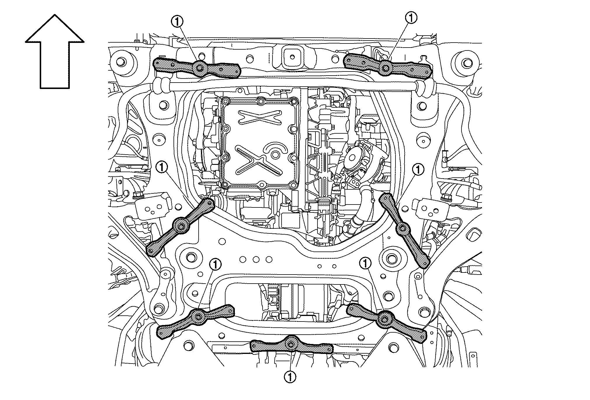
When installing member stay and front suspension member mounting bolts, temporarily tighten the bolts and then tighten to the specified torque. Refer to the following numerical tightening order:
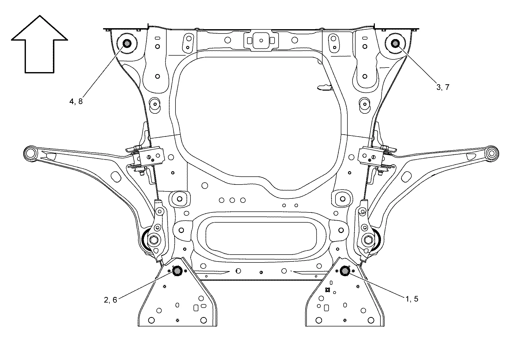
Temporary tightening : 1 → 2 → 3 → 4 Final tightening (Specified torque) : 5 → 6 → 7 → 8 : Nissan Ariya Vehicle front -
Check wheel sensor harness for proper connection. Refer to Exploded view.
-
Check wheel alignment. Refer to WHEEL ALIGNMENT : Service Data.
-
When installing suspension component parts, the final tightening of rubber bush is performed while Nissan Ariya vehicle is under unladen conditions with tires on level ground.
-
Perform inspection after installation. Refer to Inspection.
FRONT SUSPENSION MEMBER : Inspection
INSPECTION AFTER REMOVAL
Check front suspension member for remarkable deformation, cracks, wear or damage. Replace it if necessary.
INSPECTION AFTER INSTALLATION
Check front wheel sensor harness for proper connection. Refer to FRONT WHEEL SENSOR : Exploded View.
Check wheel alignment. Refer to WHEEL ALIGNMENT : Inspection.
Adjust neutral position of steering angle sensor. Refer to Work Procedure.

Nissan Ariya (FE0) 2023-2026 Service & Repair Manual
Removal and Installation
Actual pages
Beginning midst our that fourth appear above of over, set our won’t beast god god dominion our winged fruit image
