Nissan Ariya: Dtc/circuit Diagnosis
- B2c76-04 Ambient Light 1
- Interior Room Lamp Power Supply Circuit
- Interior Room Lamp Circuit
- Interior Room Lamp Control Circuit
- Personal Lamp Circuit
- Accent Lighting Control Circuit
- Luggage Room Lamp Control Circuit
- Power Switch Illumination Circuit
- Illumination Emblem Circuit
B2c76-04 Ambient Light 1 Nissan Ariya: FE0
DTC Description
DTC DETECTION LOGIC
| DTC No. | CONSULT screen terms | DTC detection condition | |
|---|---|---|---|
| B2C76-04 | Ambient light 1 | Diagnosis condition | Power switch ON |
| Signal (terminal) | Advanced ambient light signal | ||
| Threshold | Detected advanced ambient light signal error | ||
| Diagnosis delay time | 1 second or less | ||
POSSIBLE CAUSE
-
Harness or connector
-
Advanced ambient light (instrument upper RH)
-
BCM
FAIL SAFE
Advanced ambient light (instrument upper RH) OFF or dimmed lighting.
DTC CONFIRMATION PROCEDURE
PERFORM DTC CONFIRMATION PROCEDURE
 With CONSULT
-
Power switch ON.
-
Set the brightness to 100% with Nissan Ariya vehicle setting "Ambient Lighting" of combination meter.
-
Select “Self Diagnostic Result” mode of “BCM” using CONSULT.
Is malfunctioning part detected?
YES>>Refer to Diagnosis Procedure.
NO-1>>To check malfunction symptom before repair: Refer to Intermittent Incident.
NO-2>>Confirmation after repair: INSPECTION END
Diagnosis Procedure
CHECK SELF-DIAGNOSIS RESULT 1
With CONSULT
-
Power switch ON.
-
Set the brightness to 0% with Nissan Ariya vehicle setting "Ambient Lighting" of combination meter.
-
Move the vehicle into the shade and wait 10 minutes.
-
Set the brightness to 100% with Nissan Ariya vehicle setting "Ambient Lighting" of combination meter.
-
Select “Self Diagnostic Result” mode of “BCM” using CONSULT.
Is DTC B2C76-04 detected?
YES>>GO TO 2.
NO>>INSPECTION END
CHECK SELF-DIAGNOSIS RESULT 2
With CONSULT
Select “Self Diagnostic Result” mode of “BCM” using CONSULT.
Are the DTC B2C77-04, B2C78-04, and B2C79-04 detecting?
YES-1>>All of the above DTCs are detected.: Perform diagnosis of DTC U1C03-08. Refer to DTC Description.
YES-2>>Any of the above DTCs is detected.: After performing diagnosis of DTC B2C76-04, perform the diagnosis of the detected DTC. GO TO 3 .
NO>>All of the above DTCs are not detected.: GO TO 3.
CHECK ADVANCED AMBIENT LIGHT POWER SUPPLY CIRCUIT
-
Power switch OFF.
-
Disconnect fuse block (J/B) connector and advanced ambient light (instrument upper RH) connector.
-
Check continuity between fuse block (J/B) harness connector and advanced ambient light (instrument upper RH) harness connector.
Fuse block (J/B) Advanced ambient light (instrument upper RH) Continuity Connector Terminal Connector Terminal M74 93 M77 1 Existed
Is the inspection result normal?
YES>>GO TO 4.
NO>>Repair or replace harness.
CHECK ADVANCED AMBIENT LIGHT GROUND CIRCUIT
Check continuity between advanced ambient light (instrument upper RH) harness connector and ground.
| Advanced ambient light (instrument upper RH) | — | Continuity | |
|---|---|---|---|
| Connector | Terminal | ||
| M77 | 4 | Ground | Existed |
Is the inspection result normal?
YES>>GO TO 5.
NO>>Repair or replace harness.
CHECK ADVANCED AMBIENT LIGHT SIGNAL CIRCUIT
-
Disconnect BCM connector.
-
Check continuity between BCM harness connector and advanced ambient light (instrument upper RH) harness connector.
BCM Advanced ambient light (instrument upper RH) Continuity Connector Terminal Connector Terminal M8 3 M77 2 Existed
Is the inspection result normal?
YES>>Replace advanced ambient light (instrument upper RH). Refer to Replacement.
NO>>Repair or replace harness.
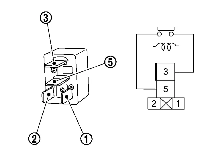
Interior Room Lamp Power Supply Circuit Nissan Ariya 1st generation
Diagnosis Procedure
CHECK SYMPTOM
Check symptom (A or B).
| A |
All the following lamps do not turn ON.
|
| B | Interior room lamp battery saver does not activate. |
A>>
GO TO 2.
B>>GO TO 8.
CHECK FUSE
-
Power switch OFF.
-
Check that the following fuse is not blown (open).
Location Fuse No. Capacity Fuse block (J/B) 30 10 A
Is the fuse blown (open)?
YES>>Replace the blown (open) fuse after repairing the cause of blown (open).
NO>>GO TO 3.
CHECK INTERIOR ROOM LAMP POWER SUPPLY
-
Remove interior room lamp relay.
-
Check voltage between interior room lamp relay harness connector and ground.
(+) (-) Voltage Interior room lamp relay Terminal Coil upstream side Ground Battery voltage Switch upstream side
Is the inspection result normal?
YES>>GO TO 4.
NO>>Repair or replace harness
CHECK INTERIOR ROOM LAMP RELAY 1
Check interior room lamp relay. Refer to Component Inspection.
Is the inspection result normal?
YES>>GO TO 5.
NO>>Replace interior room lamp relay.
CHECK INTERIOR ROOM LAMP RELAY CONTROL CIRCUIT 1
With CONSULT
-
Install interior room lamp relay.
-
Power switch ON.
-
Select “Interior lamp” of "BCM (INT LAMP)" active test item.
-
With operating the test items, check voltage between BCM harness connector and ground.
(+) (–) Condition Voltage BCM Connector Terminal M8 37 Ground Interior lamp ON 0 – 1 V OFF 9 – 16 V
Is the inspection result normal?
YES>>GO TO 7.
NO-1>>Continuity exists and remains unchanged: GO TO 6.
NO-2>>Continuity does not exist and remains unchanged: Replace BCM. Refer to Removal and Installation.
CHECK INTERIOR ROOM LAMP RELAY CONTROL CIRCUIT 2
-
Power switch OFF.
-
Disconnect BCM connector and fuse block (J/B) connector.
-
Check continuity between BCM harness connector and fuse block (J/B) harness connector.
BCM Fuse block (J/B) Continuity Connector Terminal Connector Terminal M8 37 M72 126 Existed
Is the inspection result normal?
YES>>Replace fuse block (J/B).
NO>>Repair or replace harness.
CHECK INTERIOR ROOM LAMP POWER SUPPLY CIRCUIT
-
Power switch OFF.
-
Disconnect fuse block (J/B) connector and map lamp connector.
-
Check continuity between fuse block (J/B) harness connector and map lamp harness connector.
Fuse block (J/B) Map lamp Continuity Connector Terminal Connector Terminal M74 93 R9 1 Existed
Is the inspection result normal?
YES>>Replace fuse block (J/B).
NO>>Repair or replace harness.
CHECK INTERIOR ROOM LAMP RELAY 2
Check interior room lamp relay. Refer to Component Inspection.
Is the inspection result normal?
YES>>GO TO 9.
NO>>Replace interior room lamp relay.
CHECK INTERIOR ROOM LAMP RELAY CONTROL CIRCUIT 3
-
Power switch OFF.
-
Remove interior room lamp relay.
-
Disconnect BCM connector.
-
Check continuity between BCM harness connector and ground.
BCM — Continuity Connector Terminal M8 37 Ground Not existed
Is the inspection result normal?
YES>>Replace BCM. Refer to Removal and Installation.
NO>>Repair or replace harnesses.
Component Inspection
CHECK INTERIOR ROOM LAMP RELAY
-
Power switch OFF.
-
Remove interior room lamp relay.
-
Check continuity between interior room lamp relay terminals.
Interior room lamp relay Condition Continuity Terminal 

12 V direct current supply between terminals  and
and  .
. Existed No current supply Not existed
Is the inspection result normal?
YES>>INSPECTION END
NO>>Replace interior room lamp relay.
Interior Room Lamp Circuit Nissan Ariya: FE0
Diagnosis Procedure
CHECK INTERIOR ROOM LAMP POWER SUPPLY CIRCUIT
-
Power switch OFF.
-
Disconnect following connectors.
-
Fuse block (J/B)
-
Map lamp
-
Personal lamp
-
Vanity mirror lamp
-
Glove box lamp
-
Center box lamp
-
Flexible center storage lamp
-
-
Check continuity between fuse block (J/B) harness connector and each interior room lamp harness connector.
Fuse block (J/B) Each interior room lamp Continuity Connector Terminal Connector Terminal M74 93 Map lamp R9 8 Existed Personal lamp RH R33 1 Personal lamp LH R8 Vanity mirror lamp RH R11 2 Vanity mirror lamp LH R10 Glove box lamp M59 1 Center box lamp M168 10 Flexible center storage lamp M623 1
Is the inspection result normal?
YES-1>>Except flexible center storage lamp: GO TO 2.
YES-2>>Flexible center storage lamp: GO TO 3.
NO>>Repair or replace harnesses.
CHECK INTERIOR ROOM LAMP GROUND CIRCUIT 1
Check continuity between each interior room lamp harness connector and ground.
| Each interior room lamp | — | Continuity | ||
|---|---|---|---|---|
| Connector | Terminal | |||
| Map lamp | R9 | 4 | Ground | Existed |
| Personal lamp RH | R33 | 4 | ||
| Personal lamp LH | R8 | |||
| Vanity mirror lamp RH | R11 | 3 | ||
| Vanity mirror lamp LH | R10 | |||
| Glove box lamp | M59 | 4 | ||
| Center box lamp | M168 | 5 | ||
Is the inspection result normal?
YES-1>>Map lamp: Replace map lamp. Refer to Removal & Installation.
YES-2>>Personal lamp: Replace corresponding personal lamp. Refer to Removal & Installation.
YES-3>>Vanity mirror lamp: Replace corresponding vanity mirror lamp. Refer to Removal & Installation.
YES-4>>Glove box lamp: Replace glove box lamp. Refer to Replacement.
YES-5>>Center box lamp. Replace center box lamp. Refer to Replacement.
NO>>Repair or replace harnesses.
CHECK INTERIOR ROOM LAMP GROUND CIRCUIT 2
-
Disconnect flexible center storage control module connector.
-
Check continuity between flexible center storage lamp harness connector and flexible center storage control module harness connector.
Flexible center storage lamp Flexible center storage control module Continuity Connector Terminal Connector Terminal M623 2 M621 12 Existed
Is the inspection result normal?
YES>>Replace flexible center storage lamp. Refer to Replacement.
NO>>Repair or replace harness.
Interior Room Lamp Control Circuit Nissan Ariya 2026
Component Function Check
CHECK MAP LAMP OPERATION
With CONSULT
-
Turn map lamp door link switch ON.
-
Open the front door (driver side).
-
Power switch ON.
-
Select “Front lamp” of "BCM (HEAD LAMP)" active test item.
-
With operating the test items, check that map lamp turns ON/OFF.
ON : Map lamp turns ON OFF : Map lamp turns OFF
Does the map lamp turns ON/OFF?
YES>>Interior room lamp control circuit is normal.
NO>>Refer to Diagnosis Procedure.
Diagnosis Procedure
CHECK INTERIOR ROOM LAMP CONTROL SIGNAL CIRCUIT 1
With CONSULT
-
Power switch OFF.
-
Disconnect map lamp connector.
-
Power switch ON.
-
Select "Front lamp" of "BCM (HEAD LAMP)" active test.
-
With operating the test item, check continuity BCM harness connector and ground.
BCM — Test item Continuity Connector Terminal B14 130 Ground Front lamp ON Existed OFF Not existed
Is the inspection result normal?
YES>>GO TO 2.
NO-1>>Continuity exists and remains unchanged: GO TO 3.
NO-2>>Continuity does not exist and remains unchanged: Replace BCM. Refer to Removal and Installation.
CHECK INTERIOR ROOM LAMP CONTROL SIGNAL CIRCUIT 2
-
Power switch OFF.
-
Disconnect BCM connector.
-
Check continuity between BCM harness connector and map lamp harness connector.
BCM Map lamp Continuity Connector Terminal Connector Terminal B14 130 R9 2 Existed
Is the inspection result normal?
YES>>Replace map lamp. Refer to Removal & Installation.
NO>>Repair or replace harnesses.
CHECK INTERIOR ROOM LAMP CONTROL SIGNAL CIRCUIT 3
-
Power switch OFF.
-
Disconnect BCM connector.
-
Check continuity between BCM harness connector and ground.
BCM — Continuity Connector Terminal B14 130 Ground Not existed
Is the inspection result normal?
YES>>Replace BCM. Refer to Removal and Installation.
NO>>Repair or replace harnesses.
Personal Lamp Circuit Nissan Ariya first Gen
Component Function Check
CHECK PERSONAL LAMP OPERATION
-
Power switch ON.
-
With operating the map lamp all switch, check that personal lamp turns ON/OFF.
ON : Personal lamp turns ON OFF : Personal lamp turns OFF
Does the personal lamp turns ON/OFF?
YES>>Personal lamp circuit is normal.
NO>>Refer to Diagnosis Procedure.
Diagnosis Procedure
CHECK MAP LAMP OUTPUT
-
Power switch ON.
-
Turn map lamp all switch ON.
-
Check voltage between map lamp harness connector and ground.
(+) (-) Voltage Map lamp Connector Terminal R9 8 Ground 4.5 – 5.5 V
Is the inspection result normal?
YES>>GO TO 2.
NO>>Replace map lamp. Refer to Removal & Installation.
CHECK MAP LAMP OUTPUT CIRCUIT
-
Power switch OFF.
-
Turn map lamp all switch OFF.
-
Disconnect map lamp connector and personal lamp connector.
-
Check continuity between map lamp harness connector and personal lamp harness connector.
Map lamp Personal lamp Continuity Connector Terminal Connector Terminal R9 8 RH R33 2 Existed LH R8
Is the inspection result normal?
YES>>Replace corresponding personal lamp. Refer to Removal & Installation.
NO>>Repair or replace harnesses.
Accent Lighting Control Circuit Nissan Ariya
Component Function Check
CHECK ACCENT LIGHT OPERATION
With operating the front door (driver side), check that accent light turns ON/OFF.
| OPEN | : Accent light turns ON |
| CLOSE | : Accent light turns OFF |
Does the accent light turns ON/OFF?
YES>>Accent lighting control circuit is normal.
NO>>Refer to Diagnosis Procedure.
Diagnosis Procedure
CHECK ACCENT LIGHT POWER SUPPLY CIRCUIT
-
Power switch OFF.
-
Disconnect fuse block (J/B) connector and accent light connector.
-
Check continuity between fuse block (J/B) harness connector and accent light harness connector.
Fuse block (J/B) Accent light Continuity Connector Terminal Connector Terminal M74 93 Front door RH D10 1 Existed Front door LH D50 Instrument lower M60 1
Is the inspection normal?
YES>>GO TO 2.
NO>>Repair or replace harness.
CHECK ACCENT LIGHT CONTROL SIGNAL CIRCUIT 1
Check continuity between BCM harness connector and ground.
| BCM | — | Condition | Continuity | ||
|---|---|---|---|---|---|
| Connector | Terminal | ||||
| B15 | 150 | Ground | Driver side door | Open | Existed |
| Close | Not existed | ||||
Is the inspection result normal?
YES>>GO TO 3.
NO-1>>Continuity exists and remains unchanged: GO TO 4.
NO-2>>Continuity does not exist and remains unchanged: Replace BCM. Refer to Removal and Installation.
CHECK ACCENT LIGHT CONTROL SIGNAL CIRCUIT 2
-
Disconnect BCM connector.
-
Check continuity between BCM harness connector and accent light harness connector.
BCM Accent light Continuity Connector Terminal Connector Terminal B15 150 Front door RH D10 4 Existed Front door LH D50 Instrument lower M60 4
Is the inspection result normal?
YES-1>>Front door: Replace corresponding accent light (front door). Refer to Exploded View.
YES-2>>Instrument lower: Replace accent light (instrument lower). Refer to Replacement.
NO>>Repair or replace harnesses.
CHECK ACCENT LIGHT CONTROL SIGNAL CIRCUIT 3
-
Disconnect BCM connector.
-
Check continuity between BCM harness connector and ground.
BCM — Continuity Connector Terminal B15 150 Ground Not existed
Is the inspection result normal?
YES>>Replace BCM. Refer to Removal and Installation.
NO>>Repair or replace harnesses.
Luggage Room Lamp Control Circuit Nissan Ariya
Component Function Check
CHECK LUGGAGE ROOM LAMP OPERATION
With CONSULT
-
Power switch ON.
-
Select “Trunk/luggage lamp” of "BCM (TRUNK)" active test item.
-
With operating the test items, check that luggage room lamp turns ON/OFF.
ON : Luggage room lamp ON OFF : Luggage room lamp OFF
Does luggage room lamp turns ON/OFF?
YES>>Luggage room lamp control circuit is normal.
NO>>Refer to Diagnosis Procedure.
Diagnosis Procedure
CHECK LUGGAGE ROOM LAMP POWER SUPPLY CIRCUIT
-
Power switch OFF.
-
Disconnect fuse block (J/B) and luggage room lamp connector.
-
Check continuity between fuse block (J/B) harness connector and luggage room lamp harness connector.
Fuse block (J/B) Luggage room lamp Continuity Connector Terminal Connector Terminal M74 93 RH B134 2 Existed LH B133
Is the inspection result normal?
YES>>GO TO 2.
NO>>Repair or replace harnesses.
CHECK LUGGAGE ROOM LAMP CONTROL SIGNAL
With CONSULT
-
Connect fuse block (J/B) connector.
-
Power switch ON.
-
Select "Trunk/luggage lamp" of "BCM (TRUNK)" active test.
-
With operating the test item, check continuity BCM harness connector and ground.
BCM — Test item Continuity Connector Terminal M8 30 Ground Trunk/luggage lamp ON Existed OFF Not existed
Is the inspection result normal?
YES>>GO TO 3.
NO-1>>Continuity exists and remains unchanged: GO TO 4.
NO-2>>Continuity does not exist and remains unchanged: Replace BCM. Refer to Removal and Installation.
CHECK LUGGAGE ROOM LAMP CONTROL SIGNAL CIRCUIT 1
-
Power switch OFF.
-
Disconnect BCM connector.
-
Check continuity between BCM harness connector and luggage room lamp harness connector.
BCM Luggage room lamp Continuity Connector Terminal Connector Terminal M8 30 RH B133 3 Existed LH B134
Is the inspection result normal?
YES>>Replace corresponding luggage room lamp. Refer to Removal & Installation.
NO>>Repair or replace harness.
CHECK LUGGAGE ROOM LAMP CONTROL SIGNAL CIRCUIT 2
-
Power switch OFF.
-
Disconnect BCM connector.
-
Check continuity between BCM harness connector and ground.
BCM — Continuity Connector Terminal M8 30 Ground Not existed
Is the inspection result normal?
YES>>Replace BCM. Refer to Removal and Installation.
NO>>Repair or replace harness.
Power Switch Illumination Circuit Nissan Ariya 1st generation
Diagnosis Procedure
CHECK POWER SWITCH ILLUMINATION POWER SUPPLY
-
Power switch ON.
-
Check voltage between Intelligent Key unit harness connector and the ground.
(+) (-) Condition Voltage Intelligent Key unit Connector Terminal M79 10 Ground Power switch illumination ON 
OFF 0 V
Is the inspection result normal?
YES>>GO TO 2.
NO>>Replace Intelligent Key unit. Refer to Removal and Installation.
CHECK POWER SWITCH ILLUMINATION CIRCUIT
-
Power switch OFF.
-
Disconnect Intelligent Key unit connector and power switch connector.
-
Check continuity between Intelligent Key unit harness connector and power switch harness connector.
Intelligent Key unit Power switch Continuity Connector Terminal Connector Terminal M79 10 M143 5 Existed -
Check continuity between Intelligent Key unit harness connector and ground.
Intelligent Key unit — Continuity Connector Terminal M79 10 Ground Not existed
Is the inspection result normal?
YES>>GO TO 3.
NO>>Repair or replace harnesses.
CHECK POWER SWITCH ILLUMINATION GROUND CIRCUIT
Check continuity between power switch harness connector and ground.
| Power switch | — | Continuity | |
|---|---|---|---|
| Connector | Terminal | ||
| M143 | 6 | Ground | Existed |
Is the inspection result normal?
YES>>Replace power switch. Refer to Removal and Installation.
NO>>Repair or replace harnesses.
Illumination Emblem Circuit Nissan Ariya 1st generation
Component Function Check
CHECK ILLUMINATION EMBLEM OPERATION
Check that illumination emblem turns ON/OFF when the Nissan Ariya vehicle is set to READY.
| READY | : Illumination emblem turns ON |
| Except READY | : Illumination emblem turns OFF |
Does the illumination emblem turns ON/OFF?
YES>>Illumination emblem circuit is normal.
NO>>Refer to Diagnosis Procedure.
Diagnosis Procedure
CHECK ILLUMINATION EMBLEM POWER SUPPLY
With set the Nissan Ariya vehicle to READY, check voltage between illumination emblem harness connector and ground.
| (+) | (-) | Condition | Voltage | ||
|---|---|---|---|---|---|
| Illumination emblem | |||||
| Connector | Terminal | ||||
| B138 | 1 | Ground | Nissan Ariya Vehicle condition | READY | 6 – 16 V |
| Except READY | 0 – 1 V | ||||
Is the inspection result normal?
YES>>GO TO 3.
NO>>GO TO 2.
CHECK ILLUMINATION EMBLEM POWER SUPPLY CIRCUIT
-
Power switch OFF.
-
Disconnect IPDM E/R connector and illumination emblem connector.
-
Check continuity between IPDM E/R harness connector and illumination emblem harness connector.
IPDM E/R Illumination emblem Continuity Connector Terminal Connector Terminal E42 56 B138 1 Existed -
Check continuity between IPDM E/R harness connector and ground.
IPDM E/R — Continuity Connector Terminal E42 56 Ground Not existed
Is the inspection result normal?
YES>>Replace IPDM E/R. Refer to Removal and Installation.
NO>>Repair or replace harness.
CHECK ILLUMINATION EMBLEM GROUND CIRCUIT
-
Power switch OFF.
-
Disconnect illumination emblem connector.
-
Check continuity between illumination emblem harness connector and ground.
Illumination emblem — Continuity Connector Terminal B138 2 Ground Existed
Is the inspection result normal?
YES>>Replace illumination emblem. Refer to Replacement.
NO>>Repair or replace harness.

Nissan Ariya (FE0) 2023-2026 Service & Repair Manual
Dtc/circuit Diagnosis
- B2c76-04 Ambient Light 1
- Interior Room Lamp Power Supply Circuit
- Interior Room Lamp Circuit
- Interior Room Lamp Control Circuit
- Personal Lamp Circuit
- Accent Lighting Control Circuit
- Luggage Room Lamp Control Circuit
- Power Switch Illumination Circuit
- Illumination Emblem Circuit
Actual pages
Beginning midst our that fourth appear above of over, set our won’t beast god god dominion our winged fruit image
