Nissan Ariya: Li-Ion Battery Insulation Resistance Loss Inspection
2wd
Diagnosis Procedure
WARNING:
-
Be sure to remove the service plug in order to disconnect the high voltage circuits before performing inspection or maintenance of high voltage system harnesses and parts.
-
The removed service plug must always be carried in a pocket of the responsible worker or placed in the tool box during the procedure to prevent the plug from being connected by mistake.
-
Be sure to wear insulating protective equipment consisting of glove, shoes, face shield and glasses before beginning work on the high voltage system.
-
Never allow workers other than the responsible person to touch the Nissan Ariya vehicle containing high voltage parts. To keep others from touching the high voltage parts, these parts must be covered with an insulating sheet except when using them.
-
Refer to PRECAUTIONS FOR HIGH VOLTAGE : Precautions.
CAUTION:
Never bring the vehicle into the READY status with the service plug removed unless otherwise instructed in the Service Manual. A malfunction may occur if this is not observed.
 NOTE:
NOTE:
To check a stable value, have time enough after putting a probe.
CAUTION:
-
The following diagnosis procedure must be performed when “P1BA2-49” are detected and Li-ion battery is judged that its insulation resistance is dropping.
-
Be sure to perform procedure till the last. And write down a memo about the malfunctioning parts. Insulation resistance may be lost in some parts.
CHECK MAXIMUM CELL VOLTAGE
 With CONSULT
-
Power switch ON.
-
Select “Data Monitor” of “HIGH VOLTAGE BATTERY”.
-
Record “Maximum cell voltage”.
NOTE:
When procedure for replacing malfunction module is required, “MAXIMUM CELL VOLTAGE” is used.
>>
GO TO 2.
PRECONDITIONING
WARNING:
Be sure to perform the high voltage disconnection and voltage check in high voltage circuit before inspection.
-
Disconnect the high voltage. Refer to HOW TO DISCONNECT HIGH VOLTAGE : Precautions.
-
Check voltage in high voltage circuit. Refer to CHECK VOLTAGE IN HIGH VOLTAGE CIRCUIT : Precautions.
-
Remove Li-ion battery. Refer to Removal & Installation.
-
Remove battery pack upper case. Refer to Removal & Installation.
-
Remove LBC. Refer to Removal & Installation.
>>
GO TO 3.
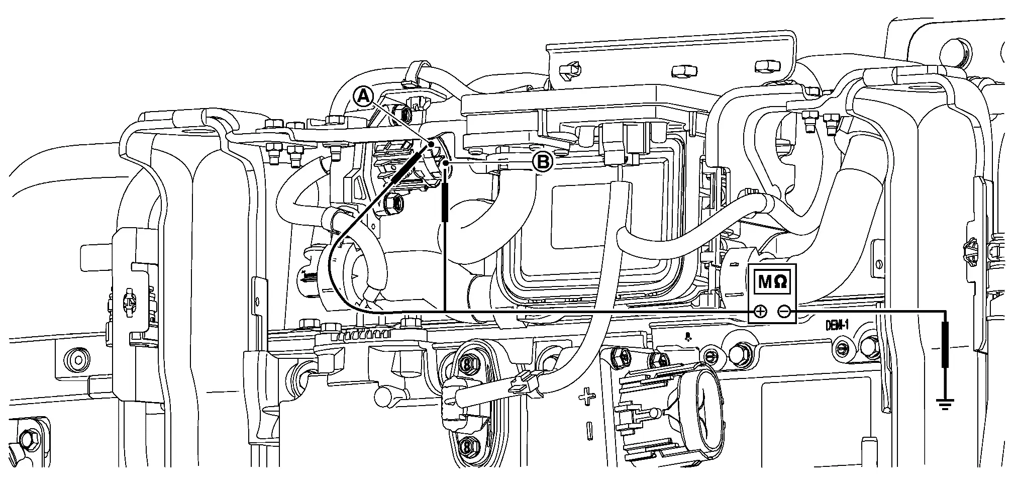
CHECK INSULATION RESISTANCE OF HIGH-VOLTAGE CONNECTOR (FRONT) AND HIGH-VOLTAGE CONNECTOR (QUICK CHARGE)
Using insulation resistance tester, measure insulation resistance between terminals of high-voltage connector (front) and high voltage connector (quick charge).
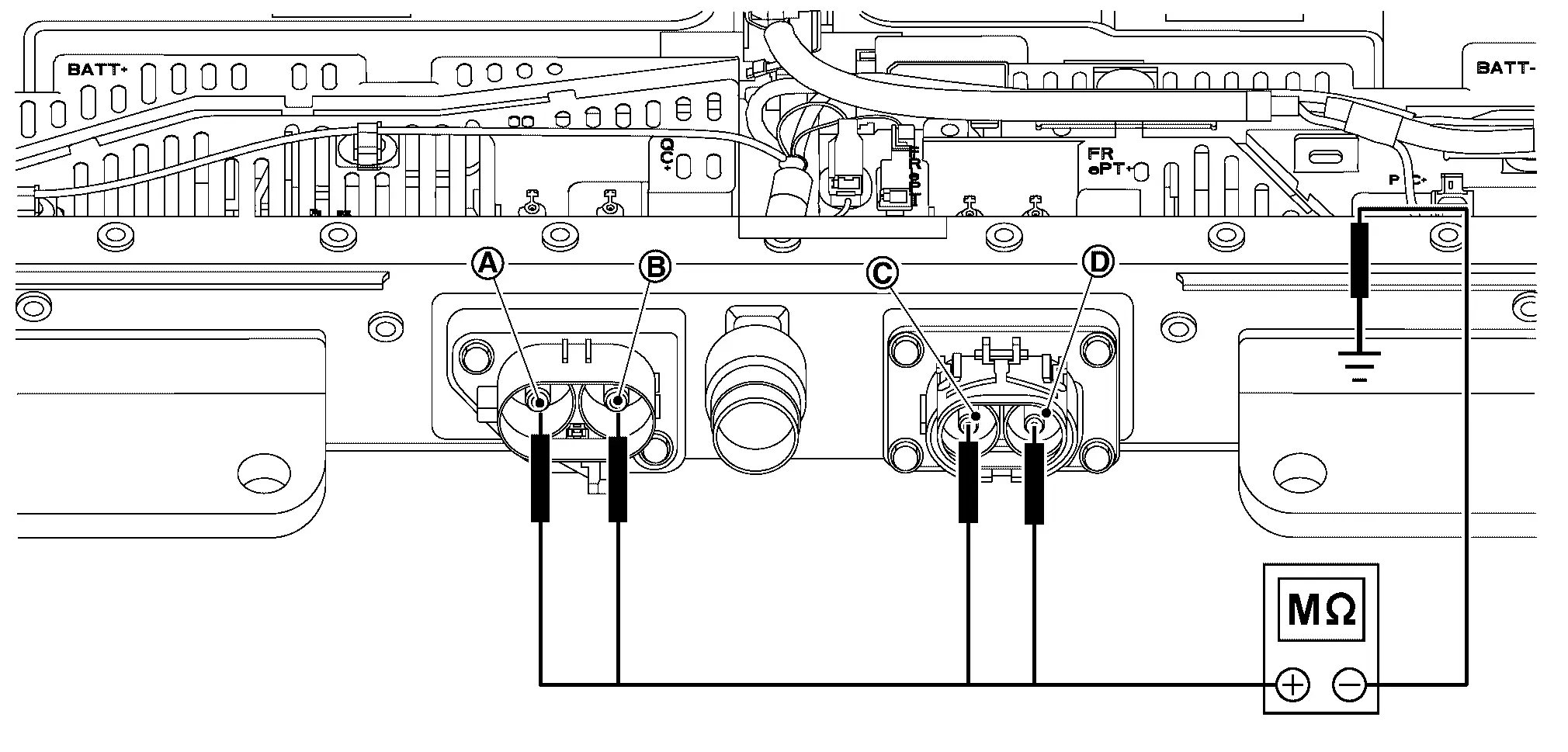
| Probe | Resistance | |
|---|---|---|
| + | − | |
High-voltage connector (Front) terminal |
Battery pack lower case | 1000 MΩ or more |
High-voltage connector (Front) terminal |
||
High-voltage connector (Quick charge) terminal |
||
High-voltage connector (Quick charge) terminal |
||
WARNING:
Unlike the ordinary tester, the insulation resistance tester applies 500 V when measuring.
If used incorrectly, there is the danger of electric shock. If used in the Nissan Ariya vehicle 12 V system, there is the danger of damage to electronic devices. Read the insulation resistance tester instruction manual carefully and be sure to work safely.
CAUTION:
-
Be sure to set the insulation resistance tester to 500 V when performing this test.
-
Using a setting higher than 500 V can result in damage to the component being inspected.
-
When probe is pot on the battery lower case, put it on the part that is not corroded or soiled.
Is the inspection result normal?
YES>>GO TO 6.
NO>>GO TO 4.
CHECK BUS BAR BETWEEN HIGH VOLTAGE CONNECTOR AND JUNCTION BOX.
-
Remove high voltage connector (front) and high voltage connector (quick charge).
-
Remove each connector of junction box.
-
Remove the following bus bar.
-
Bus bar (Bus bar 1) between high voltage connector (Front) and junction box.
-
Bus bar (Bus bar 20) between high voltage connector (Quick charge) and junction box.
-
-
Check that each bus bar shield have no scratches and cracks.
Is the inspection result normal?
YES>>GO TO 5.
NO>>Take note about replaced malfunction parts. Then GO TO 5.
BATTERY JUNCTION BOX INSULATION RESISTANCE-1
-
Remove high voltage connector (Front) and high voltage connector (Quick charge).
-
Remove each connector of junction box.
-
Using insulation resistance tester, measure insulation resistance between battery junction box terminals and battery pack ground.
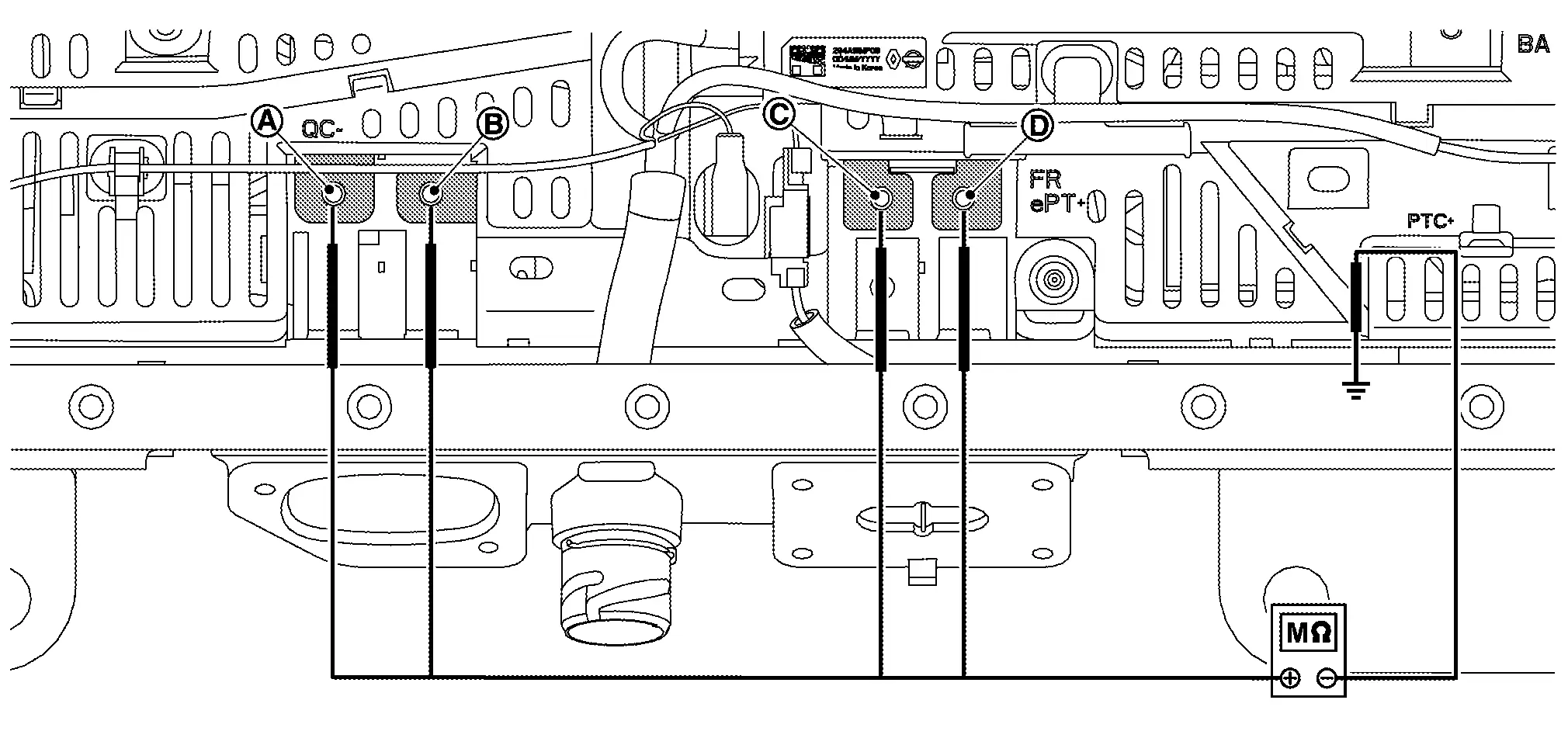
Probe Resistance + − Battery junction box terminals (P1) Battery pack lower case 1000 MΩ or more Battery junction box terminals (P3) Battery junction box terminals (P5) Battery junction box terminals (P6) WARNING:
Unlike the ordinary tester, the insulation resistance tester applies 500 V when measuring. If used incorrectly, there is the danger of electric shock. If used in the Nissan Ariya vehicle 12 V system, there is the danger of damage to electronic devices. Read the insulation resistance tester instruction manual carefully and be sure to work safely.
CAUTION:
-
Be sure to set the insulation resistance tester to 500 V when performing this test.
-
Using a setting higher than 500 V can result in damage to the component being inspected.
-
When probe is pot on the battery lower case, put it on the part that is not corroded or soiled.
-
Is the inspection result normal?
YES>>Take note about replacement of high voltage connector (Front) and high voltage connector (Quick charge) Then GO TO 6.
NO>>Take note about malfunction parts. Then GO TO 6.
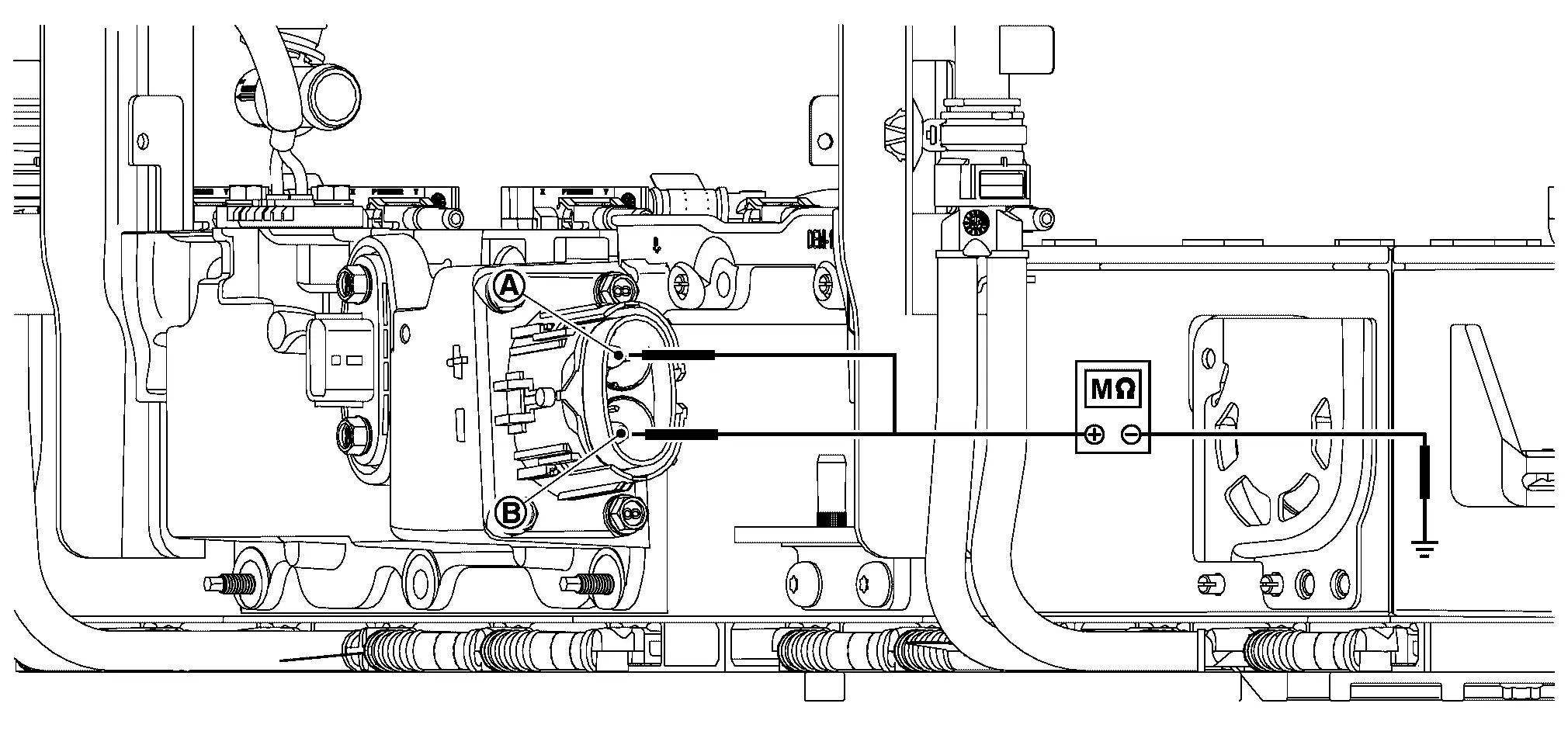
CHECK INSULATION RESISTANCE OF HIGH VOLTAGE CONNECTOR (BATTERY PTC CONNECTOR)
Using insulation resistance tester, measure insulation resistance between high-voltage connector (Battery PTC) terminals and battery pack ground (battery pack lower case).
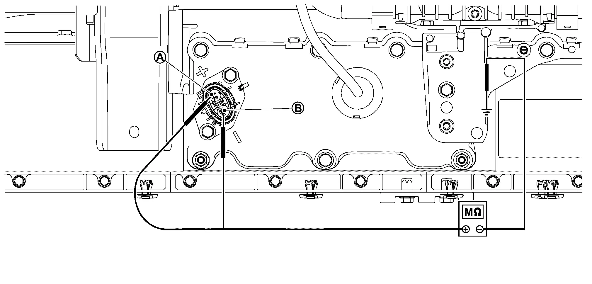
| Probe | Resistance | |
|---|---|---|
| + | − | |
| High-voltage connector (Battery PTC) terminal |
Battery pack lower case | 1000 MΩ or more |
| High-voltage connector (Battery PTC) terminal |
||
WARNING:
Unlike the ordinary tester, the insulation resistance tester applies 500 V when measuring. If used incorrectly, there is the danger of electric shock. If used in the Nissan Ariya vehicle 12V system, there is the danger of damage to electronic devices. Read the insulation resistance tester instruction manual carefully and be sure to work safely.
CAUTION:
-
Be sure to set the insulation resistance tester to 500 V when performing this test.
-
Using a setting higher than 500 V can result in damage to the component being inspected.
-
When probe is pot on the battery lower case, put it on the part that is not corroded or soiled.
Is the inspection result normal?
YES>>GO TO 8.
NO>>GO TO 7.
CHECK INSULATION RESISTANCE BETWEEN HARNESSES OF BATTERY PTC AND JUNCTION BOX
-
Remove battery PTC connector of junction box.
-
Using insulation resistance tester, measure insulation resistance between battery PTC harness and battery pack lower case.
Probe Resistance + − High-voltage connector (Battery PTC) terminal Battery pack lower case 1000 MΩ or more High-voltage connector (Battery PTC) terminal
WARNING:
Unlike the ordinary tester, the insulation resistance tester applies 500 V when measuring. If used incorrectly, there is the danger of electric shock. If used in the Nissan Ariya vehicle 12 V system, there is the danger of damage to electronic devices. Read the insulation resistance tester instruction manual carefully and be sure to work safely.
CAUTION:
-
Be sure to set the insulation resistance tester to 500 V when performing this test.
-
Using a setting higher than 500 V can result in damage to the component being inspected.
-
When probe is pot on the battery lower case, put it on the part that is not corroded or soiled.
Is the inspection result normal?
YES>>Record replacement of high voltage connector (Battery PTC) Then GO TO 8.
NO>>Record replacement of harnesses between battery PTC and junction box. Then GO TO 8.
CHECK BUS BAR BETWEEN JUNCTION BOX AND MODULE
-
Remove the following parts.
-
Bus bar (bas bar2) between junction box and module No.1.
-
Bus bar (bas bar19) between junction box and module No.12.
-
-
Check that each bus bar shield have no scratches and cracks.
Is the inspection result normal?
YES>>GO TO 9.
NO>>Record replacement of malfunction parts. Then GO TO 9.
CHECK INSULATION RESISTANCE OF BATTERY JUNCTION BOX
Using insulation resistance tester, measure insulation resistance between battery junction box and battery pack lower case.
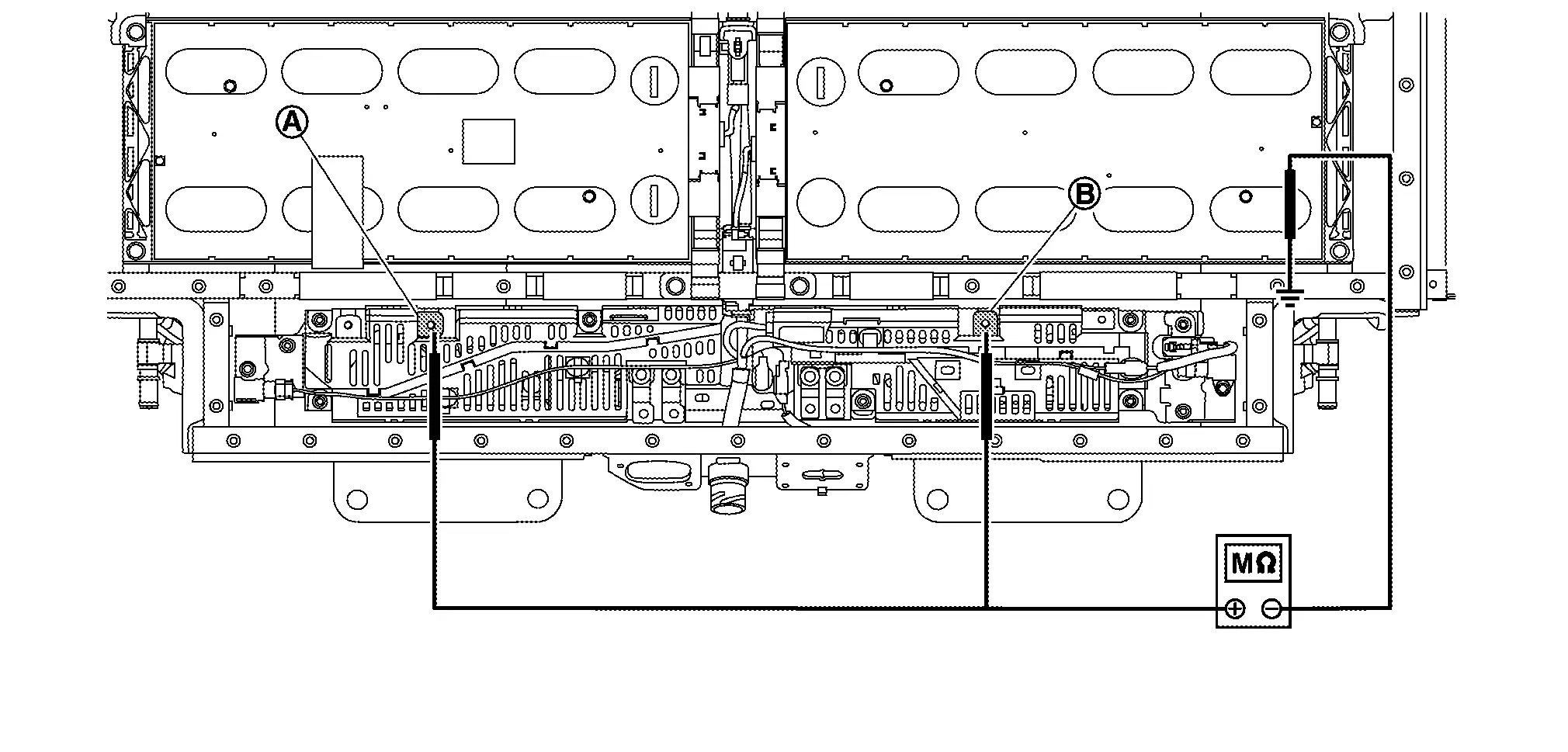
| Probe | Resistance | |
|---|---|---|
| + | − | |
| Battery junction box terminals (P2) |
Battery pack lower case | 1000 MΩ or more |
| Battery junction box terminals (P4) |
||
WARNING:
Unlike the ordinary tester, the insulation resistance tester applies 500 V when measuring. If used incorrectly, there is the danger of electric shock. If used in the Nissan Ariya vehicle 12V system, there is the danger of damage to electronic devices. Read the insulation resistance tester instruction manual carefully and be sure to work safely.
CAUTION:
-
Be sure to set the insulation resistance tester to 500 V when performing this test.
-
Using a setting higher than 500 V can result in damage to the component being inspected.
-
When probe is pot on the battery lower case, put it on the part that is not corroded or soiled.
Is the inspection result normal?
YES>>GO TO 10.
NO>>Record replacement of junction box. Then GO TO 10.
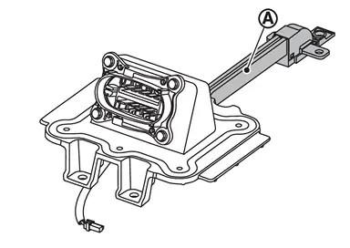
CHECK INSULATION RESISTANCE OF SERVICE PLUG SWITCH
-
Remove service plug switch bracket together with bus bar.
-
Remove bus bar
from service plug.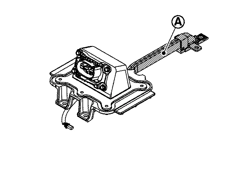
-
Check that each bus bar shield have no scratches and cracks.
-
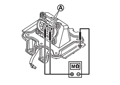
Using insulation resistance tester, measure insulation resistance between service plug switch terminal
and service plug switch bracket.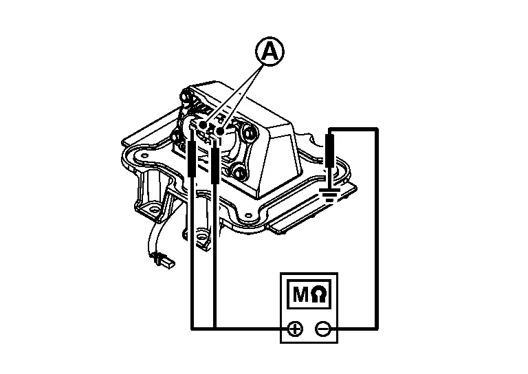
WARNING:
Unlike the ordinary tester, the insulation resistance tester applies 500 V when measuring. If used incorrectly, there is the danger of electric shock. If used in the Nissan Ariya vehicle 12 V system, there is the danger of damage to electronic devices. Read the insulation resistance tester instruction manual carefully and be sure to work safely.
CAUTION:
-
Be sure to set the insulation resistance tester to 500 V when performing this test.
-
Using a setting higher than 500 V can result in damage to the component being inspected.
-
When probe is pot on the battery lower case, put it on the part that is not corroded or soiled.
NOTE:
Check service plug switch and service plug switch bracket as an assembly.
+ − Resistance Service plug switch terminals Service plug switch bracket. 1000 MΩ or more -
Is the inspection result normal?
YES>>GO TO 12.
NO>>Record replacement of malfunction parts. Then GO TO 12.
CHECK EACH BUS BAR (2ND FLOOR)
-
Remove the following bus bars.
-
Bus bar (Bus bar 9) between module No.6 and module No.7
-
Bus bar (Bus bar 10) between module No.7 and module No.8
-
Bus bar (Bus bar 14) between module No.10 and module No.9
-
Bus bar (Bus bar 15) between module No.11 and module No.10
-
-
Check that each bus bar shield have no scratches and cracks.
Is the inspection result normal?
YES>>GO TO 12.
NO>>Record replacement of malfunction parts. Then GO TO 12.
CHECK INSULATION VOLTAGE OF MODULE (2ND FLOOR)
-
Disconnect cell voltage detecting connector of each module.
-
Measure voltage between positive and negative terminal of each module and battery lower case ground.
NOTE:
The figure shows module No. 10 as an example. Measure voltage of each module in the same procedure.
Probe Resistance + − Module positive terminal Battery pack lower case 0 V approx. Module negative terminal
Is the inspection result normal?
YES>>GO TO 13.
NO>>GO TO 17.
REMOVE BATTERY PACK 2ND FLOOR
Remove the battery pack 2nd floor.
>>
GO TO 14.
CHECK EACH BUS BAR (1ST FLOOR)
-
Remove the following bus bars.
-
Bus bar (Bus bar 3) between module No.1 and module No.2
-
Bus bar (Bus bar 4) between module No.2 and module No.3
-
Bus bar (Bus bar 5) between module No.3 and module No.4
-
Bus bar (Bus bar 6) between module No.4 and module No.5
-
Bus bar (Bus bar 7) between module No.5 and module No.6
-
Bus bar (Bus bar 8) between module No.6/11 and module No.7/10
-
Bus bar (Bus bar 16) between module No.11 and module No.12
-
Bus bar (Bus bar 17) between module No.12 and module No.13
-
Bus bar (Bus bar 18) between module No.13 and module No.14
-
Bus bar (Bus bar 19) between module No.14 and module No.15
-
Bus bar (Bus bar 20) between module No.15 and module No.16
-
-
Check that each bus bar shield have no scratches and cracks.
Is the inspection result normal?
YES>>GO TO 15.
NO>>Record replacement of malfunction parts. Then GO TO 15.
CHECK INSULATION VOLTAGE OF MODULE (1ST FLOOR)
-
Disconnect cell voltage detecting connector of each module.
-
Measure voltage between positive and negative terminal of each module and battery lower case ground.
NOTE:
The figure shows module No. 16 as an example. Measure voltage of each module in the same procedure.
Probe Resistance + − Module positive terminal Battery pack lower case 0 V approx. Module negative terminal
Is the inspection result normal?
YES>>GO TO 16.
NO>>GO TO 17.
CHECK RESULT CONFIRMATION
Confirm malfunction parts written or record by check.
Is there malfunction parts?
YES>>Replace all parts written down or recorded.
NO>>Replace LBC.
MODULE APPEARANCE CHECK
-
Remove the module that has malfunction at voltage leak check from battery pack lower case.
-
Check the module for any of the following abnormalities by comparing its appearance with other normal modules.
-
There are dents or deformation on the module surface.
-
Liquid adheres to the module surface.
-
Module emits a strong organic solvent-like odor and continues.
-
>>
Record replacement of malfunction module and GO TO 16.
Awd
Diagnosis Procedure
WARNING:
-
Be sure to remove the service plug in order to disconnect the high voltage circuits before performing inspection or maintenance of high voltage system harnesses and parts.
-
The removed service plug must always be carried in a pocket of the responsible worker or placed in the tool box during the procedure to prevent the plug from being connected by mistake.
-
Be sure to wear insulating protective equipment consisting of glove, shoes, face shield and glasses before beginning work on the high voltage system.
-
Never allow workers other than the responsible person to touch the Nissan Ariya vehicle containing high voltage parts. To keep others from touching the high voltage parts, these parts must be covered with an insulating sheet except when using them.
-
Refer to PRECAUTIONS FOR HIGH VOLTAGE : Precautions.
CAUTION:
Never bring the vehicle into the READY status with the service plug removed unless otherwise instructed in the Service Manual. A malfunction may occur if this is not observed.
NOTE:
To check a stable value, have time enough after putting a probe.
CAUTION:
-
The following diagnosis procedure must be performed when “P1BA2-49” are detected and Li-ion battery is judged that its insulation resistance is dropping.
-
Be sure to perform procedure till the last. And write down a memo about the malfunctioning parts. Insulation resistance may be lost in some parts.
CHECK MAXIMUM CELL VOLTAGE
With CONSULT
-
Power switch ON.
-
Select “Data Monitor” of “HIGH VOLTAGE BATTERY”.
-
Record “Maximum cell voltage”.
NOTE:
When procedure for replacing malfunction module is required, “MAXIMUM CELL VOLTAGE” is used.
>>
GO TO 2.
PRECONDITIONING
WARNING:
Be sure to perform the high voltage disconnection and voltage check in high voltage circuit before inspection.
-
Disconnect the high voltage. Refer to HOW TO DISCONNECT HIGH VOLTAGE : Precautions.
-
Check voltage in high voltage circuit. Refer to CHECK VOLTAGE IN HIGH VOLTAGE CIRCUIT : Precautions.
-
Remove Li-ion battery. Refer to Removal & Installation.
-
Remove battery pack upper case. Refer to Removal & Installation.
-
Remove LBC. Refer to Removal & Installation.
>>
GO TO 3.
CHECK INSULATION RESISTANCE OF HIGH-VOLTAGE CONNECTOR (FRONT) AND HIGH-VOLTAGE CONNECTOR (QUICK CHARGE)
Using insulation resistance tester, measure insulation resistance between terminals of high-voltage connector (front) and high voltage connector (quick charge).
| Probe | Resistance | |
|---|---|---|
| + | − | |
| High-voltage connector (Front) terminal |
Battery pack lower case | 1000 MΩ or more |
| High-voltage connector (Front) terminal |
||
| High-voltage connector (Quick charge) terminal |
||
| High-voltage connector (Quick charge) terminal |
||
WARNING:
Unlike the ordinary tester, the insulation resistance tester applies 500 V when measuring.
If used incorrectly, there is the danger of electric shock. If used in the Nissan Ariya vehicle 12 V system, there is the danger of damage to electronic devices. Read the insulation resistance tester instruction manual carefully and be sure to work safely.
CAUTION:
-
Be sure to set the insulation resistance tester to 500 V when performing this test.
-
Using a setting higher than 500 V can result in damage to the component being inspected.
-
When probe is pot on the battery lower case, put it on the part that is not corroded or soiled.
Is the inspection result normal?
YES>>GO TO 6.
NO>>GO TO 4.
CHECK BUS BAR BETWEEN HIGH VOLTAGE CONNECTOR AND JUNCTION BOX.
-
Remove high voltage connector (front) and high voltage connector (quick charge).
-
Remove each connector of junction box.
-
Remove the following bus bar.
-
Bus bar (Bus bar 1) between high voltage connector (Front) and junction box.
-
Bus bar (Bus bar 24) between high voltage connector (Quick charge) and junction box.
-
-
Check that each bus bar shield have no scratches and cracks.
Is the inspection result normal?
YES>>GO TO 5.
NO>>Take note about replaced malfunction parts. Then GO TO 5.
BATTERY JUNCTION BOX INSULATION RESISTANCE-1
-
Remove high voltage connector (Front) and high voltage connector (Quick charge).
-
Remove each connector of junction box.
-
Using insulation resistance tester, measure insulation resistance between battery junction box terminals and battery pack ground.
Probe Resistance + − Battery junction box terminals (P1) Battery pack lower case 1000 MΩ or more Battery junction box terminals (P3) Battery junction box terminals (P5) Battery junction box terminals (P6) WARNING:
Unlike the ordinary tester, the insulation resistance tester applies 500 V when measuring. If used incorrectly, there is the danger of electric shock. If used in the Nissan Ariya vehicle 12 V system, there is the danger of damage to electronic devices. Read the insulation resistance tester instruction manual carefully and be sure to work safely.
CAUTION:
-
Be sure to set the insulation resistance tester to 500 V when performing this test.
-
Using a setting higher than 500 V can result in damage to the component being inspected.
-
When probe is pot on the battery lower case, put it on the part that is not corroded or soiled.
-
Is the inspection result normal?
YES>>Take note about replacement of high voltage connector (Front) and high voltage connector (Quick charge) Then GO TO 6.
NO>>Take note about malfunction parts. Then GO TO 6.
CHECK INSULATION RESISTANCE OF HIGH VOLTAGE CONNECTOR (BATTERY PTC CONNECTOR)
Using insulation resistance tester, measure insulation resistance between high-voltage connector (Battery PTC) terminals and battery pack ground (battery pack lower case).
| Probe | Resistance | |
|---|---|---|
| + | − | |
| High-voltage connector (Battery PTC) terminal |
Battery pack lower case | 1000 MΩ or more |
| High-voltage connector (Battery PTC) terminal |
||
WARNING:
Unlike the ordinary tester, the insulation resistance tester applies 500 V when measuring. If used incorrectly, there is the danger of electric shock. If used in the Nissan Ariya vehicle 12V system, there is the danger of damage to electronic devices. Read the insulation resistance tester instruction manual carefully and be sure to work safely.
CAUTION:
-
Be sure to set the insulation resistance tester to 500 V when performing this test.
-
Using a setting higher than 500 V can result in damage to the component being inspected.
-
When probe is pot on the battery lower case, put it on the part that is not corroded or soiled.
Is the inspection result normal?
YES>>GO TO 8.
NO>>GO TO 7.
CHECK INSULATION RESISTANCE BETWEEN HARNESSES OF BATTERY PTC AND JUNCTION BOX
-
Remove battery PTC connector of junction box.
-
Using insulation resistance tester, measure insulation resistance between battery PTC harness and battery pack lower case.
Probe Resistance + − High-voltage connector (Battery PTC) terminal Battery pack lower case 1000 MΩ or more High-voltage connector (Battery PTC) terminal
WARNING:
Unlike the ordinary tester, the insulation resistance tester applies 500 V when measuring. If used incorrectly, there is the danger of electric shock. If used in the Nissan Ariya vehicle 12 V system, there is the danger of damage to electronic devices. Read the insulation resistance tester instruction manual carefully and be sure to work safely.
CAUTION:
-
Be sure to set the insulation resistance tester to 500 V when performing this test.
-
Using a setting higher than 500 V can result in damage to the component being inspected.
-
When probe is pot on the battery lower case, put it on the part that is not corroded or soiled.
Is the inspection result normal?
YES>>Record replacement of high voltage connector (Battery PTC) Then GO TO 8.
NO>>Record replacement of harnesses between battery PTC and junction box. Then GO TO 8.
CHECK BUS BAR BETWEEN JUNCTION BOX AND MODULE
-
Remove the following parts.
-
Bus bar (bas bar 2) between junction box and module No. 1.
-
Bus bar (bas bar 23) between junction box and module No. 16.
-
Bus bar (Bus bar 41) between junction box and rear box
-
Bus bar (Bus bar 42) between junction box and rear box
-
Bus bar (Bus bar 46) between junction box and rear box
-
Bus bar (Bus bar 47) between junction box and rear box
-
-
Check that each bus bar shield have no scratches and cracks.
Is the inspection result normal?
YES>>GO TO 9.
NO>>Record replacement of malfunction parts. Then GO TO 9.
CHECK INSULATION RESISTANCE OF BATTERY JUNCTION BOX
Using insulation resistance tester, measure insulation resistance between battery junction box and battery pack lower case.
| Probe | Resistance | |
|---|---|---|
| + | − | |
| Battery junction box terminals (P2) |
Battery pack lower case | 1000 MΩ or more |
| Battery junction box terminals (P4) |
||
WARNING:
Unlike the ordinary tester, the insulation resistance tester applies 500 V when measuring. If used incorrectly, there is the danger of electric shock. If used in the Nissan Ariya vehicle 12V system, there is the danger of damage to electronic devices. Read the insulation resistance tester instruction manual carefully and be sure to work safely.
CAUTION:
-
Be sure to set the insulation resistance tester to 500 V when performing this test.
-
Using a setting higher than 500 V can result in damage to the component being inspected.
-
When probe is pot on the battery lower case, put it on the part that is not corroded or soiled.
Is the inspection result normal?
YES>>GO TO 10.
NO>>Record replacement of junction box. Then GO TO 10.
CHECK INSULATION RESISTANCE OF SERVICE PLUG SWITCH
-
Remove service plug switch bracket together with bus bar.
-
Remove bus bar
from service plug.TYPE A
TYPE B
-
Check that each bus bar shield have no scratches and cracks.
-
Using insulation resistance tester, measure insulation resistance between service plug switch terminal
and service plug switch bracket.TYPE A
TYPE B
WARNING:
Unlike the ordinary tester, the insulation resistance tester applies 500 V when measuring. If used incorrectly, there is the danger of electric shock. If used in the Nissan Ariya vehicle 12 V system, there is the danger of damage to electronic devices. Read the insulation resistance tester instruction manual carefully and be sure to work safely.
CAUTION:
-
Be sure to set the insulation resistance tester to 500 V when performing this test.
-
Using a setting higher than 500 V can result in damage to the component being inspected.
-
When probe is pot on the battery lower case, put it on the part that is not corroded or soiled.
NOTE:
Check service plug switch and service plug switch bracket as an assembly.
+ − Resistance Service plug switch terminals Service plug switch bracket. 1000 MΩ or more -
Is the inspection result normal?
YES>>GO TO 11.
NO>>Record replacement of malfunction parts. Then GO TO 11.
CHECK EACH BUS BAR (2ND FLOOR)
-
Remove the following bus bars.
-
Bus bar (Bus bar 10) between module No. 6 and module No. 7
-
Bus bar (Bus bar 11) between module No. 7 and module No. 8
-
Bus bar (Bus bar 15) between module No. 10 and module No. 9
-
Bus bar (Bus bar 16) between module No. 11 and module No. 10
-
-
Check that each bus bar shield have no scratches and cracks.
Is the inspection result normal?
YES>>GO TO 12.
NO>>Record replacement of malfunction parts. Then GO TO 12.
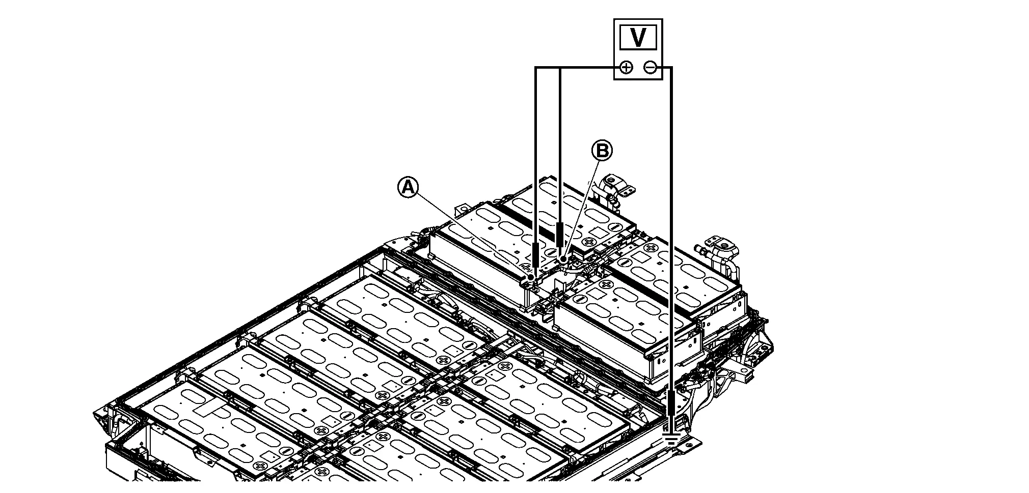
CHECK INSULATION VOLTAGE OF MODULE (2ND FLOOR)
-
Disconnect cell voltage detecting connector of each module.
-
Measure voltage between positive and negative terminal of each module and battery lower case ground.
NOTE:
The figure shows module No. 10 as an example. Measure voltage of each module in the same procedure.
Probe Resistance + − Module positive terminal Battery pack lower case 0 V approx. Module negative terminal
Is the inspection result normal?
YES>>GO TO 13.
NO>>GO TO 17.
REMOVE BATTERY PACK 2ND FLOOR
Remove the battery pack 2nd floor.
>>
GO TO 14.
CHECK EACH BUS BAR (1ST FLOOR)
-
Remove the following bus bars.
-
Bus bar (Bus bar 3) between module No. 1 and module No. 2
-
Bus bar (Bus bar 4) between module No. 2 and module No. 3
-
Bus bar (Bus bar 5) between module No. 3 and module No. 4
-
Bus bar (Bus bar 6 and 7) between module No. 4 and module No. 5
-
Bus bar (Bus bar 8) between module No. 5 and module No. 6
-
Bus bar (Bus bar 9) between module No. 6/11 and module No. 7/10
-
Bus bar (Bus bar 17) between module No. 11 and module No. 12
-
Bus bar (Bus bar 18 and 19) between module No. 12 and module No. 13
-
Bus bar (Bus bar 20) between module No. 13 and module No. 14
-
Bus bar (Bus bar 21) between module No. 14 and module No. 15
-
Bus bar (Bus bar 22) between module No. 15 and module No. 16
-
Bus bar (Bus bar 20) between module No. 15 and module No. 16
-
Bus bar (Bus bar 43) between junction box and rear box
-
Bus bar (Bus bar 44) between junction box and rear box
-
Bus bar (Bus bar 45) between junction box and rear box
-
-
Check that each bus bar shield have no scratches and cracks.
Is the inspection result normal?
YES>>GO TO 15.
NO>>Record replacement of malfunction parts. Then GO TO 15.
CHECK INSULATION RESISTANCE OF HIGH-VOLTAGE CONNECTOR (REAR)
Using insulation resistance tester, measure insulation resistance between terminals of high-voltage connector (rear).
| Probe | Resistance | |
|---|---|---|
| + | − | |
| High-voltage connector (Rear) terminal |
Battery pack lower case | 1000 MΩ or more |
| High-voltage connector (Rear) terminal |
||
WARNING:
Unlike the ordinary tester, the insulation resistance tester applies 500 V when measuring.
If used incorrectly, there is the danger of electric shock. If used in the Nissan Ariya vehicle 12 V system, there is the danger of damage to electronic devices. Read the insulation resistance tester instruction manual carefully and be sure to work safely.
CAUTION:
-
Be sure to set the insulation resistance tester to 500 V when performing this test.
-
Using a setting higher than 500 V can result in damage to the component being inspected.
-
When probe is pot on the battery lower case, put it on the part that is not corroded or soiled.
Is the inspection result normal?
YES>>GO TO 16.
NO>>Record replacement of high-voltage connector (rear). Then GO TO 16.
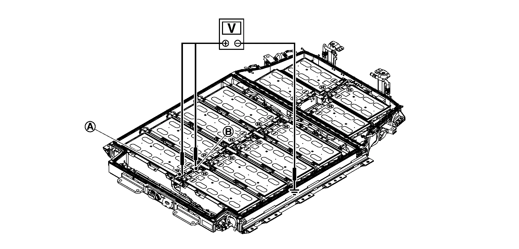
CHECK INSULATION VOLTAGE OF MODULE (1ST FLOOR)
-
Disconnect cell voltage detecting connector of each module.
-
Measure voltage between positive and negative terminal of each module and battery lower case ground.
NOTE:
The figure shows module No. 16 as an example. Measure voltage of each module in the same procedure.
Probe Resistance + − Module positive terminal Battery pack lower case 0 V approx. Module negative terminal
Is the inspection result normal?
YES>>GO TO 17.
NO>>GO TO 18.
CHECK RESULT CONFIRMATION
Confirm malfunction parts written or record by check.
Is there malfunction parts?
YES>>Replace all parts written down or recorded.
NO>>Replace LBC.
MODULE APPEARANCE CHECK
-
Remove the module that has malfunction at voltage leak check from battery pack lower case.
-
Check the module for any of the following abnormalities by comparing its appearance with other normal modules.
-
There are dents or deformation on the module surface.
-
Liquid adheres to the module surface.
-
Module emits a strong organic solvent-like odor and continues.
-
>>
Record replacement of malfunction module and GO TO 17.

Nissan Ariya (FE0) 2023-2025 Service & Repair Manual
Li-Ion Battery Insulation Resistance Loss Inspection
Actual pages
Beginning midst our that fourth appear above of over, set our won’t beast god god dominion our winged fruit image
