Nissan Ariya: Removal and Installation
Inverter (front)
INVERTER (FRONT) : Exploded View
INVERTER (FRONT) AND FRONT TRACTION MOTOR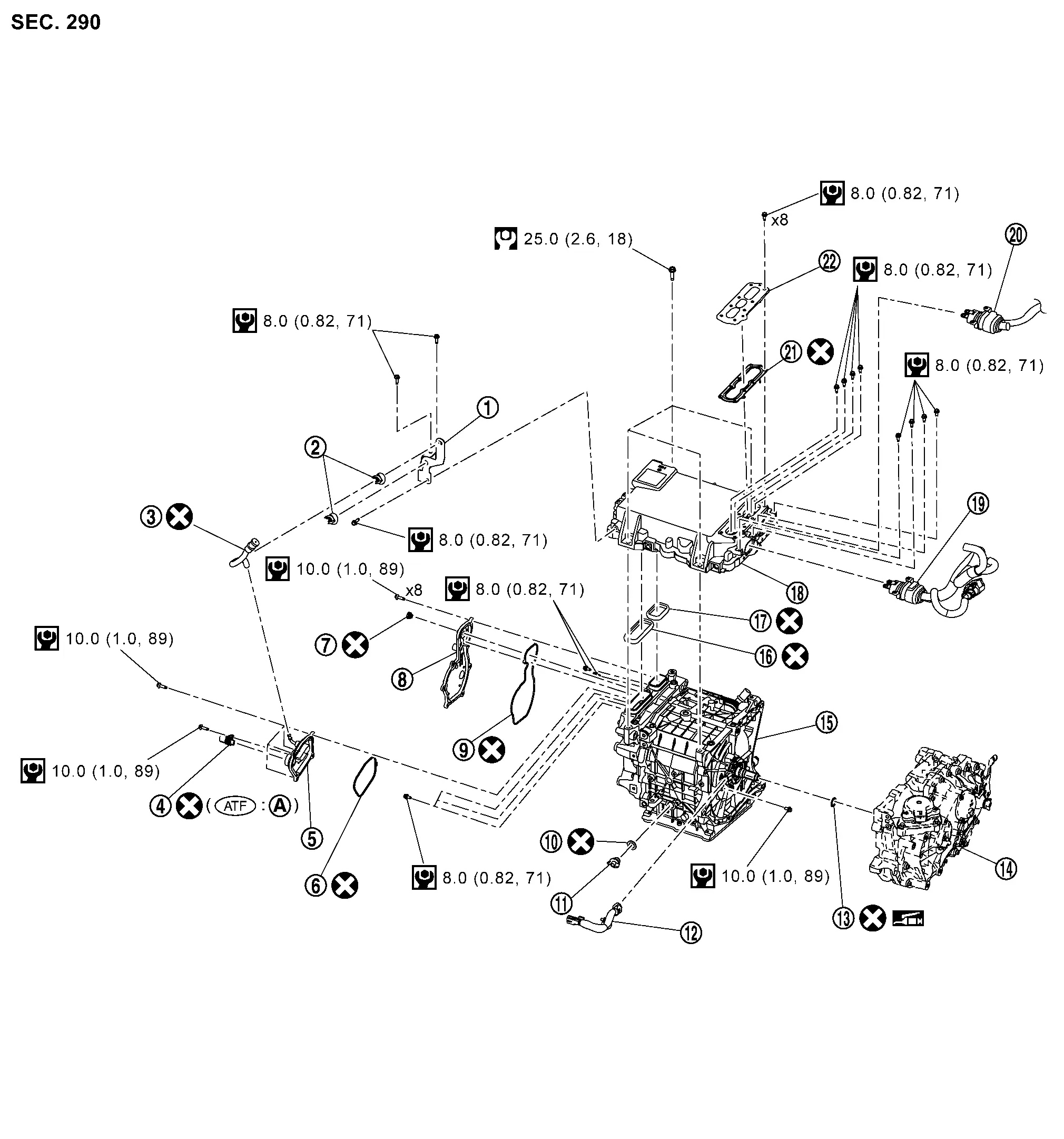
 |
Bracket |  |
Clip |  |
Air breather hose |
 |
Front traction motor stator temperature sensor joint connector |  |
3-phase bus bar cover |  |
Gasket |
 |
Breather |  |
Excitation cover |  |
Gasket |
 |
Gasket |  |
Plug |  |
Resolver harness |
 |
O-ring |  |
Reduction gear |  |
Front traction motor |
 |
Seal |  |
Seal |  |
Inverter (front) |
 |
High voltage harness |  |
High voltage harness |  |
Gasket |
 |
High voltage harness cover |  |
O-ring | ||
 |
: Always replace after every disassembly. | ||||
 |
: N·m (kg-m, in-lb) | ||||
 |
: N·m (kg-m, ft-lb) | ||||
 |
: Apply lithium-based grease including molybdenum disulphide. | ||||
 |
: Apply Genuine NISSAN Matic S ATF or equivalent. | ||||
FRONT TRACTION MOTOR MOUNTING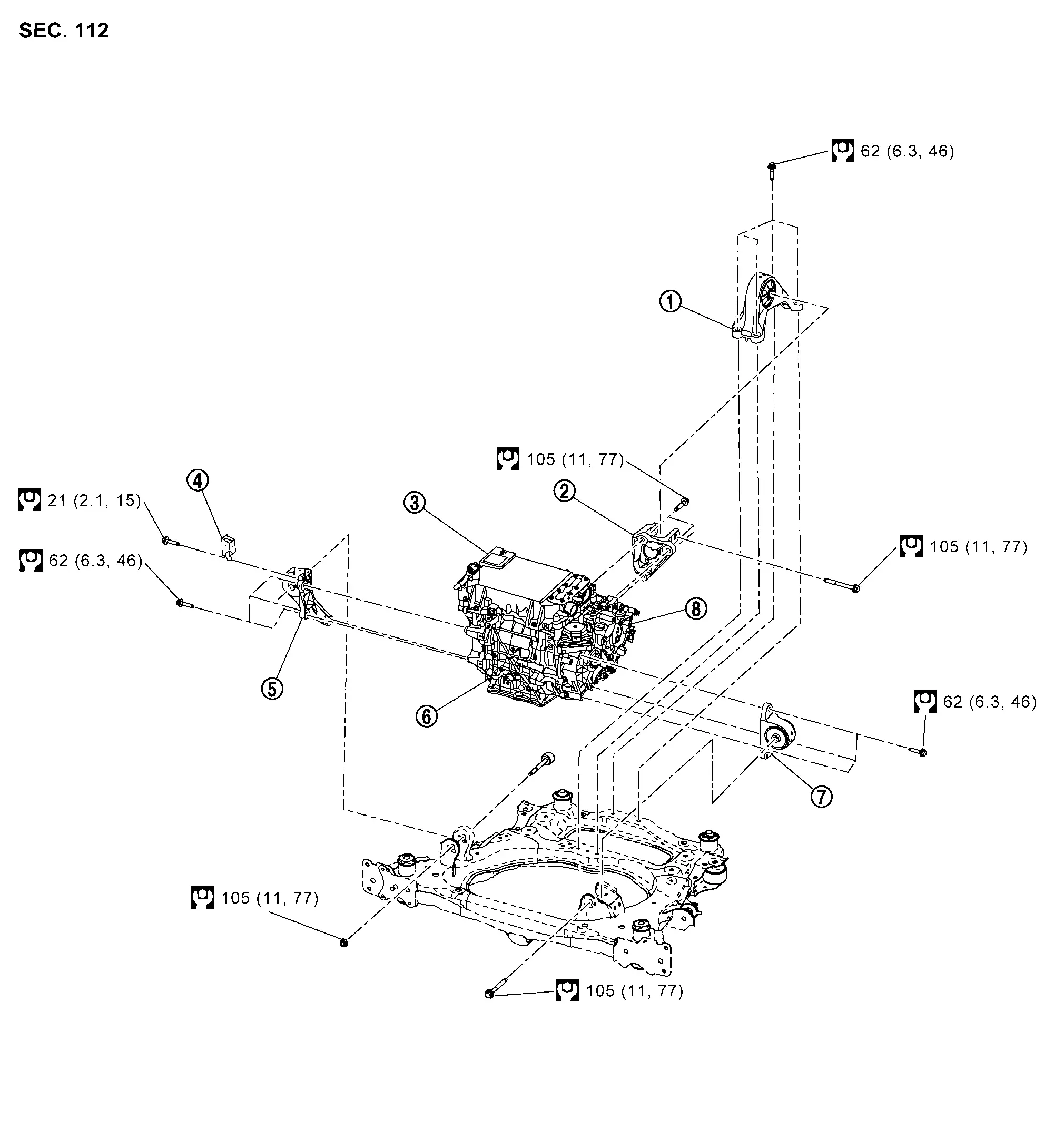
|
Motor mounting rear | |
Motor mounting bracket rear | |
Inverter (front) |
|
Bracket | |
Motor mounting RH | |
Front traction motor |
|
Motor mounting LH | |
Reduction gear | ||
|
: N·m (kg-m, ft-lb) |
INVERTER (FRONT) : Removal & Installation
DANGER: Since hybrid vehicles and electric vehicles contain a high voltage battery, there is the risk of electric shock, electric leakage, or similar accidents if the high voltage component and Nissan Ariya vehicle are handled incorrectly. Be sure to follow the correct work procedures when performing inspection and maintenance.
WARNING:
-
Be sure to remove the service plug in order to disconnect the high voltage circuits before performing inspection or maintenance of high voltage system harnesses and parts.
-
The removed service plug must always be carried in a pocket of the responsible worker or placed in the tool box during the procedure to prevent the plug from being connected by mistake.
-
Be sure to wear insulating protective equipment consisting of glove, shoes, face shield and glasses before beginning work on the high voltage system.
-
Never allow workers other than the responsible person to touch the Nissan Ariya vehicle containing high voltage parts. To keep others from touching the high voltage parts, these parts must be covered with an insulating sheet except when using them.
-
Refer to HIGH VOLTAGE PRECAUTIONS : Precautions.
CAUTION:
-
Never bring the vehicle into the READY status with the service plug removed unless otherwise instructed in the Service Manual. A malfunction may occur if this is not observed.
-
Never remove plug and gasket of front traction motor. If they are removed by mistake, replace the gasket with a new one and install them.
REMOVAL
WARNING:
Follow the instructions below before starting the procedure.
-
Disconnect high voltage circuit. Refer to HOW TO DISCONNECT HIGH VOLTAGE : Precautions.
-
Check the voltage in the high voltage circuit. Refer to CHECK VOLTAGE IN HIGH VOLTAGE CIRCUIT : Precautions.
Remove inverter (front), front traction motor and reduction gear from vehicle together as suspension member assembly. Refer to FRONT SUSPENSION MEMBER : Removal & Installation.
Remove the electric compressor, low-pressure flexible hose, and high-pressure flexible hose together. Refer to Removal & Installation.
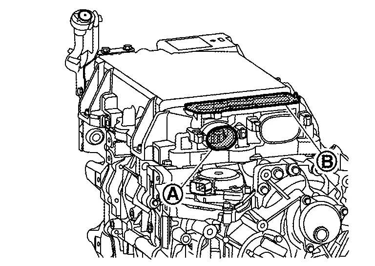
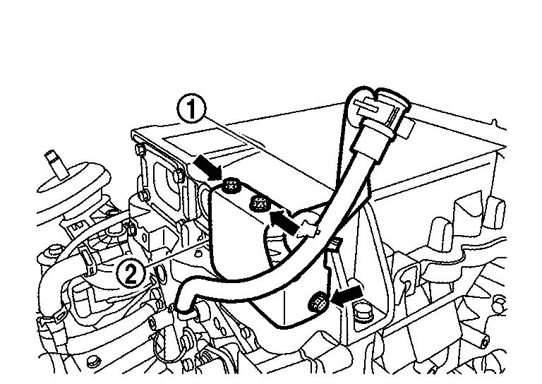
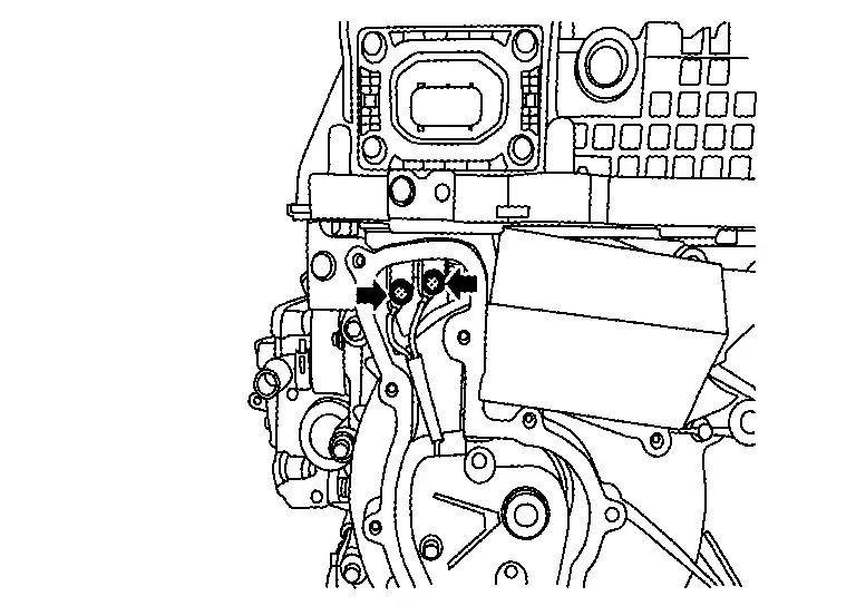
Remove high voltage harness terminal mounting bolts ( ).
).
WARNING:
To prevent electric shock hazards, be sure to put on insulating protective gear before beginning work on the high voltage system.


Remove high voltage harness mounting bolts (), and then disconnect high voltage harness .
WARNING:
To prevent electric shock hazards, be sure to put on insulating protective gear before beginning work on the high voltage system.
CAUTION:
Cover the opening and  with tape to prevent dust, dirt, foreign material, etc. from entering the inverter (front) after removing the high voltage harness mounting bolt.
Remove harness bracket mounting bolt (), and then remove water hose and harness bracket .
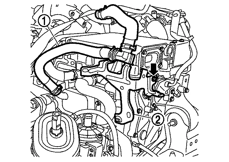
Remove harness bracket mounting bolt (), and then remove water hose and harness bracket .
Remove the water hose .
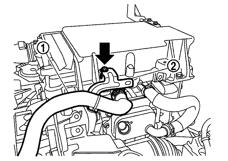
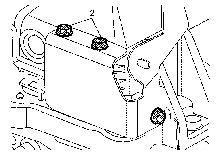
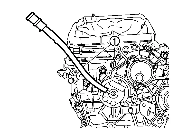
Remove the bracket mounting bolts ()and remove the breather hose and bracket .
CAUTION:
If the air breather hose was pulled out, do not reuse the air breather hose.
Attach sling belts to the inverter (front), front traction motor, and reduction gear, and prepare to separate them from the front suspension member assembly.
CAUTION:
When attaching the sling belts, avoid locations of connectors and other parts that are easily damaged.
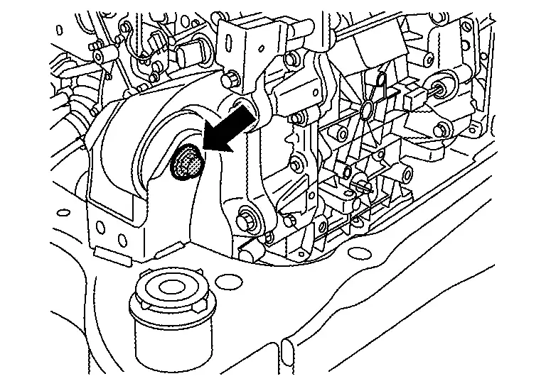
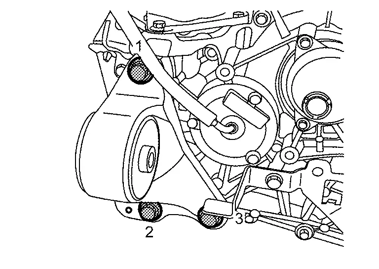
Remove joint bolt () of motor mounting bracket rear and motor mounting rear.
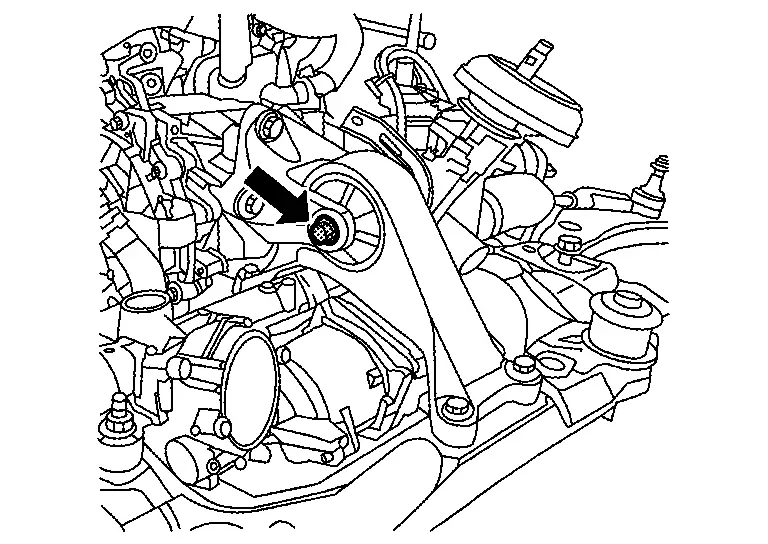
Remove joint bolt () of motor mounting bracket LH and motor mounting LH.
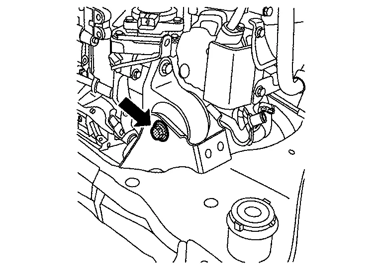
Remove joint bolt () of motor mounting bracket RH and motor mounting RH.
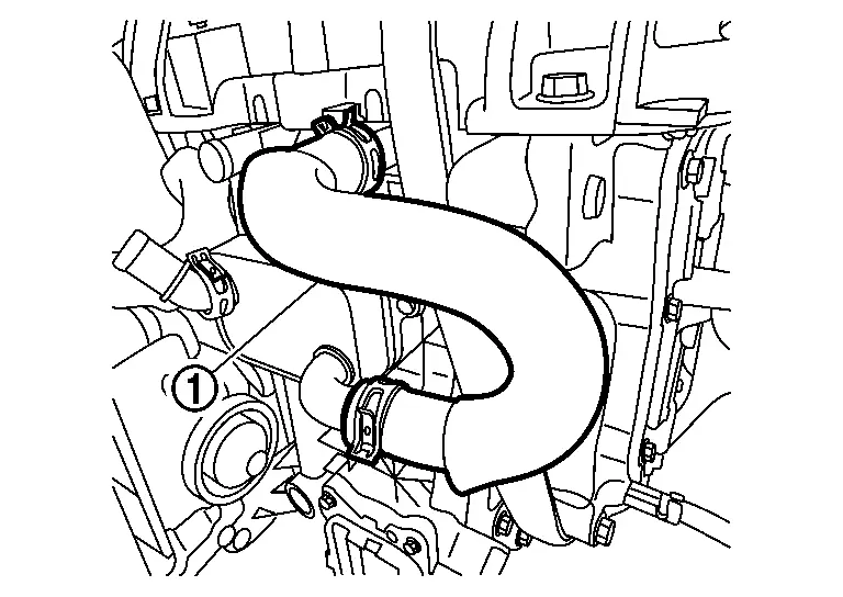
Remove the water hose from electric water pump for Li-ion battery, and then remove the electric water pump. Refer to ELECTRIC WATER PUMP : Removal & Installation.
Remove the water hose from electric water pump, and then remove the electric water pump. Refer to ELECTRIC WATER PUMP : Removal & Installation.
Use a hoist to lift up the inverter (front), front traction motor, and reduction gear, and separate them from the front suspension member assembly.
CAUTION:
Lift slowly and be careful that the inverter (front), front traction motor, and reduction gear do not fall.
WARNING:
To prevent electric shock hazards, be sure to put on insulating protective gear before beginning work on the high voltage system.
Slowly lower the inverter (front), front traction motor, and reduction gear onto sandbags or similar objects, then disconnect the sling belts from the hoist.
CAUTION:
Use pieces of wood or other means to maintain the balance to prevent the inverter (front), front traction motor, and reduction gear from falling over.
Remove motor mounting bolts (), and then remove motor mounting RH .
Remove harness bracket mounting bolt ( ), and then remove harness bracket .
Remove three-phase bus bar cover mounting bolts (), and then remove three-phase bus bar cover .
WARNING:
When performing high voltage system operations, be sure to wear insulated protective gear.
CAUTION:
-
Do not remove the stator temperature sensor joint connector for the front traction motor from the three-phase bus bar cover.
-
The stator temperature sensor joint connector for the front traction motor is a non-reusable part. Do not reuse it.
-
Oil may leak out from the opening. If it does, use cloth or other material to wipe it up.
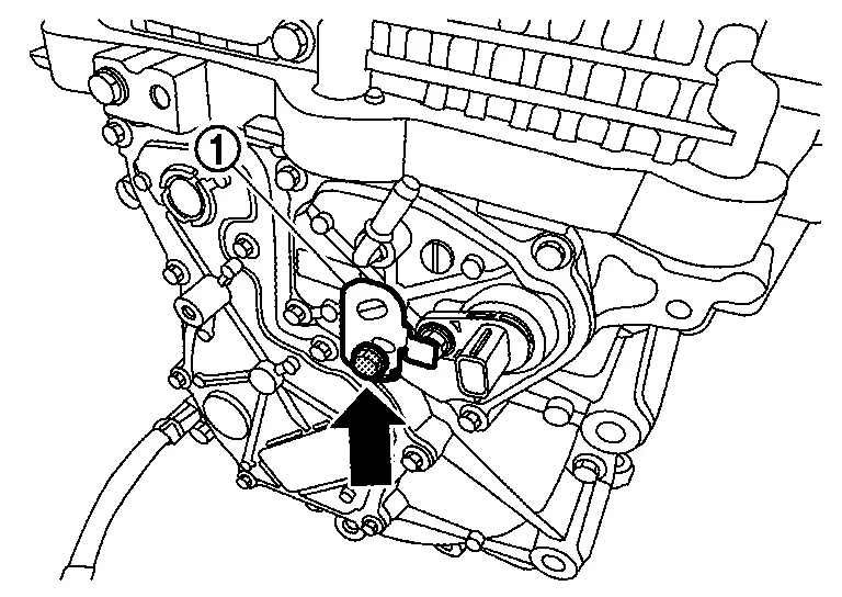
Disconnect the front traction motor stator temperature sensor harness connector .
Remove the gasket .
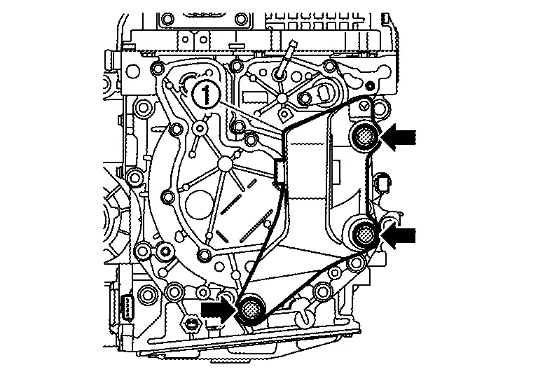
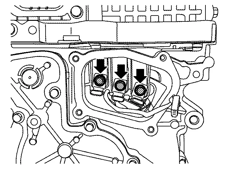
Remove three-phase bus bar terminal mounting bolts ().
WARNING:
When performing high voltage system operations, be sure to wear insulated protective gear.
CAUTION:
-
Never allow a terminal fixing bolt for the three-phase bus bar to fall into the inverter (front) during the removal operation.
-
If the terminals of three-phase harness have insulation tubes
, do not to drop insulation tubes inside the front traction motor when removing the fixing bolts.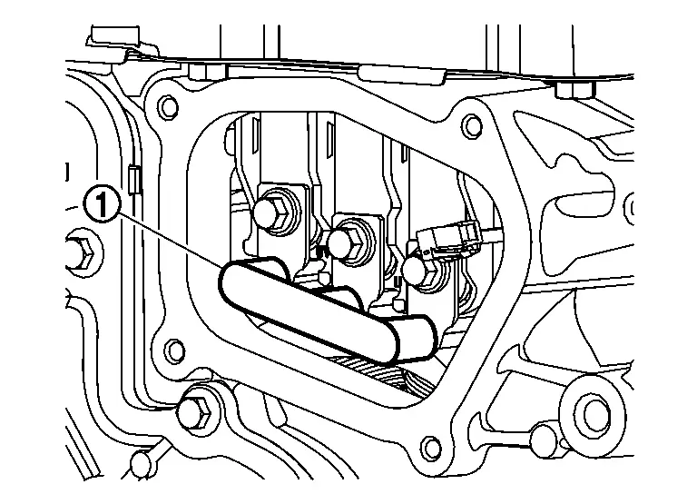
-
After loosening the terminal fixing bolts on the three-phase bus bar, cover all openings
of the inverter (front) with tape or other similar material to prevent contamination from dust, dirt, or other foreign materials. When the Nissan Ariya vehicle needs to be left as it is for a prolonged period of time, place the three-phase bus bar cover in the original position.
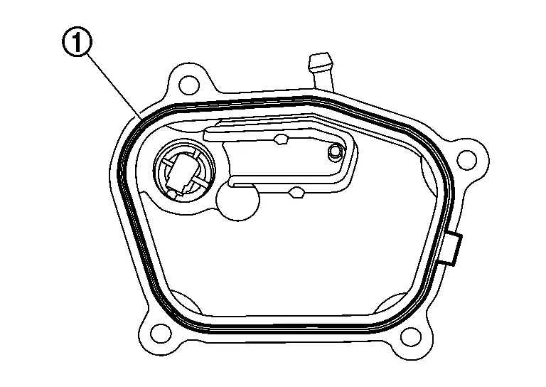
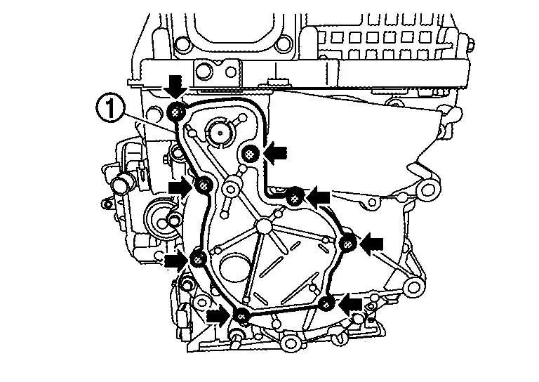
Remove excitation cover mounting bolts (), and then remove excitation cover .
WARNING:
When performing high voltage system operations, be sure to wear insulated protective gear.
CAUTION:
-
Do not remove the breather from the excitation cover.
-
Never reuse breather.
Remove the excitation cover gasket .
Remove excitation-phase bus bar terminal mounting bolts ().
WARNING:
When performing high voltage system operations, be sure to wear insulated protective gear.
Remove mounting bolts () of inverter (front).
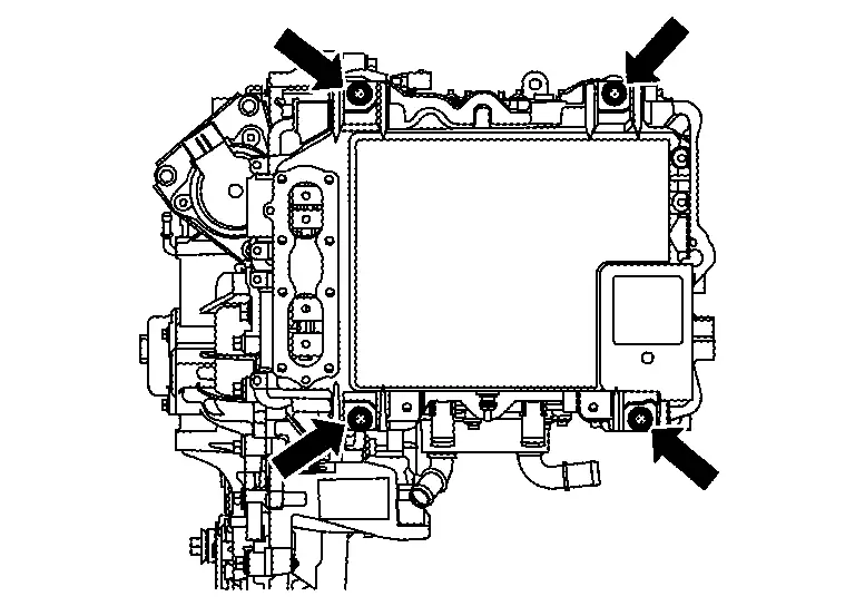
Remove the inverter (front).
CAUTION:
-
Keep the inverter (front) in the horizontal position when removing it.
-
Never bend or hit the three-phase bus bar.
-
When leaving the inverter (front), use wooden blocks to prevent three-phase bus bar interference.
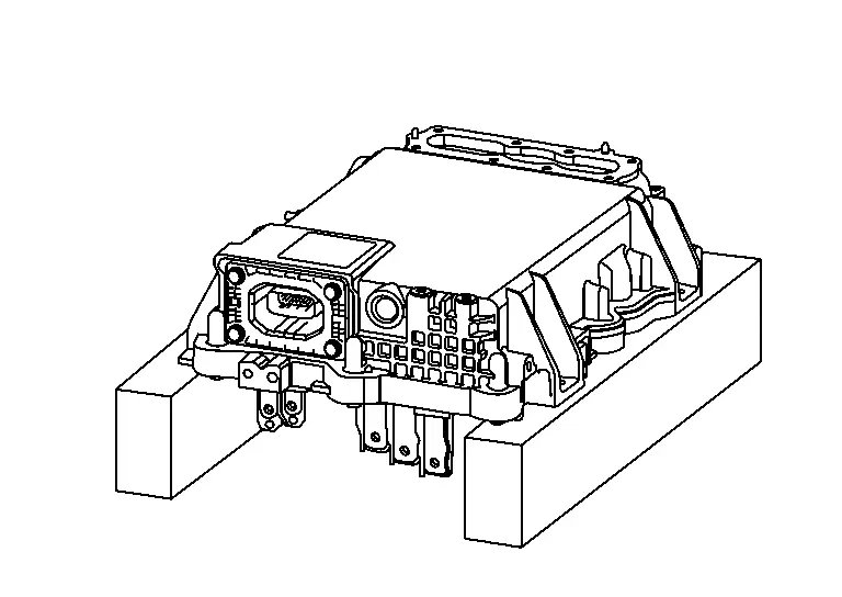
-
Cover the three-phase bus bar with shop cloth
.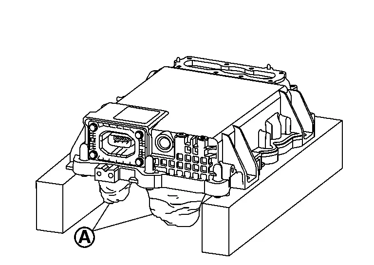
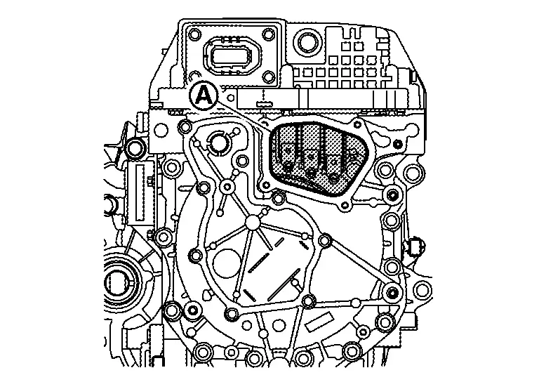
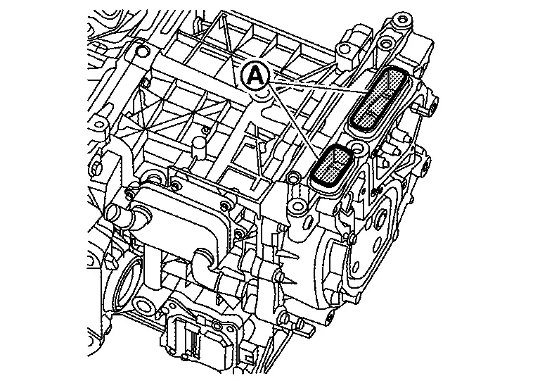
Remove the seal on the excitation bus bar opening on the front traction motor side, and remove the seal on the three-phase bus bar opening.
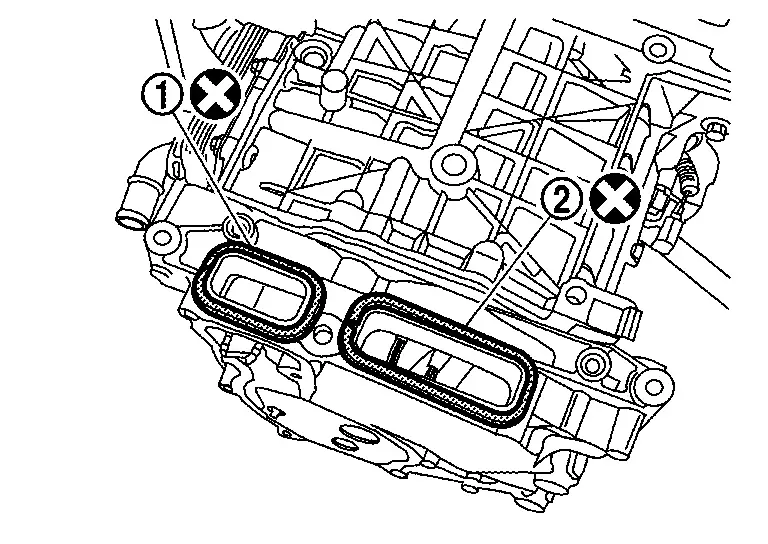
CAUTION:
-
After removing inverter (front), cover the opening
with tape to prevent dust, dirt, foreign material, etc. from entering them. -
Never reuse the seal
of excitation bus bar opening of the front traction motor side and the seal of three-phase bus bar opening after removal.
INSTALLATION
Note the following, and install in the reverse order of removal.
WARNING:
To prevent electric shock hazards, be sure to put on insulating protective gear before beginning work on the high voltage system.
CAUTION:
When the inverter (front) is replaced, perform "ADDITIONAL SERVICE WHEN REPLACING INVERTER (FRONT)". Refer to Work Procedure.
-
When the inverter (front) is installed, never bend three phase bus bar and excitation bus bar or give impact.
-
If the breather was removed from the excitation cover or replaced:
-
Check that the O-ring is securely installed before installing the breather.
-
After installing the breather, insert straight so that the distance the breather installation dimension from the edge of the case is A.
Step from edge of excitation cover to breather edge (A) : 0.55 mm (0.0217 in) 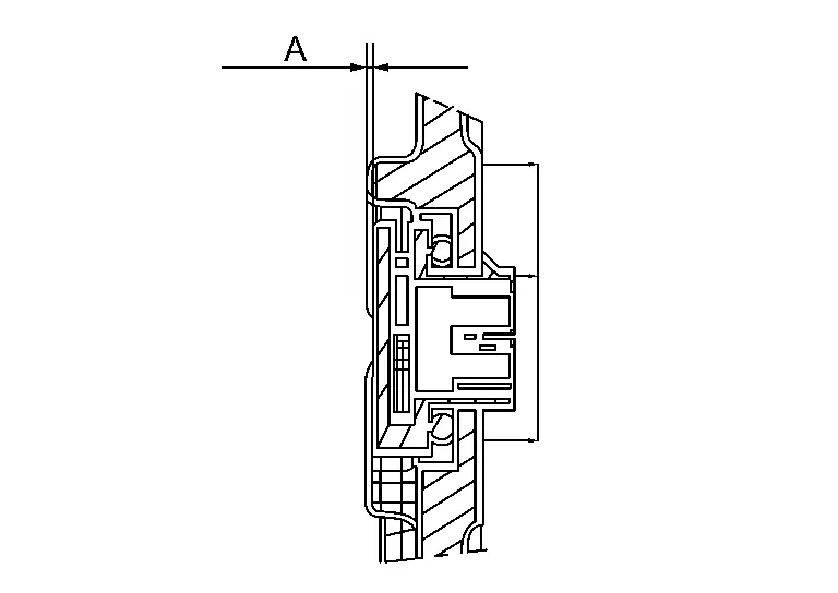
-
-
When installing the excitation wiring harness onto the excitation bus bar, install the red harness terminal (Ex+)
onto the right side excitation bus bar, and the blue harness terminal (Ex-) onto the left excitation bus bar.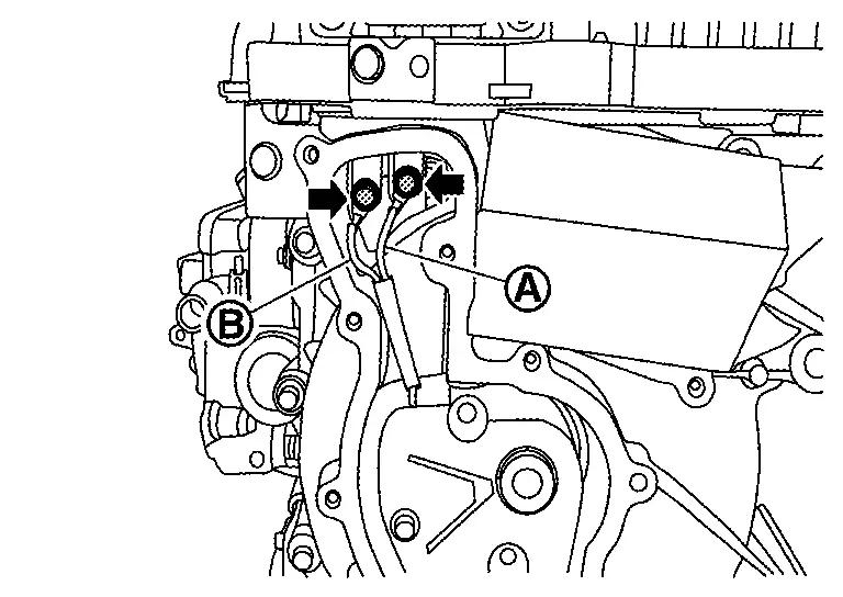
-
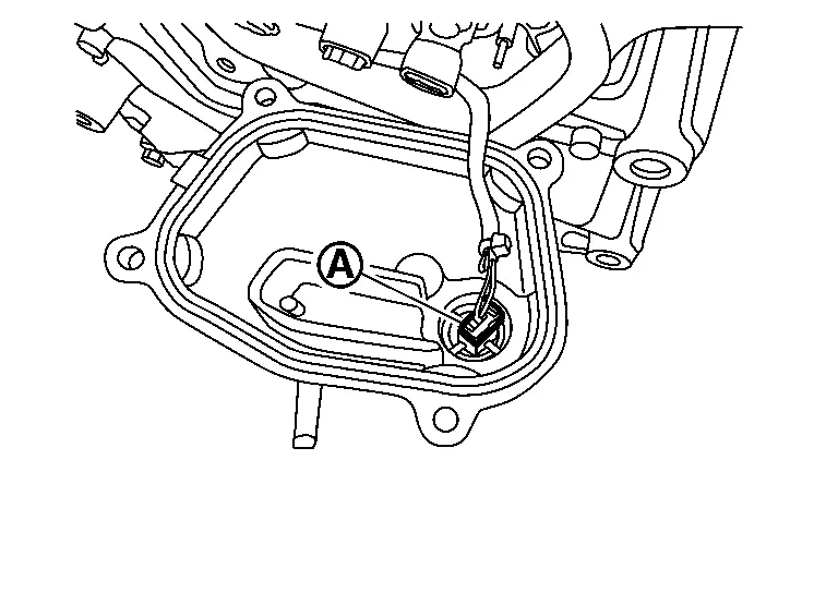
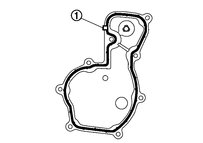
When installing the excitation cover gasket
, check that the tab (A) is securely installed. The gasket is non-reusable part. Do not reuse it.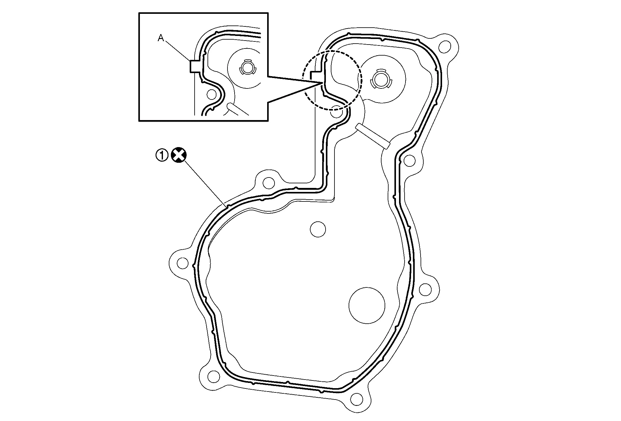
-
Follow the procedure below to install the excitation cover.
-
Tighten excitation cover mounting bolts to the temporarily tighten them in numerical order shown in the figure.
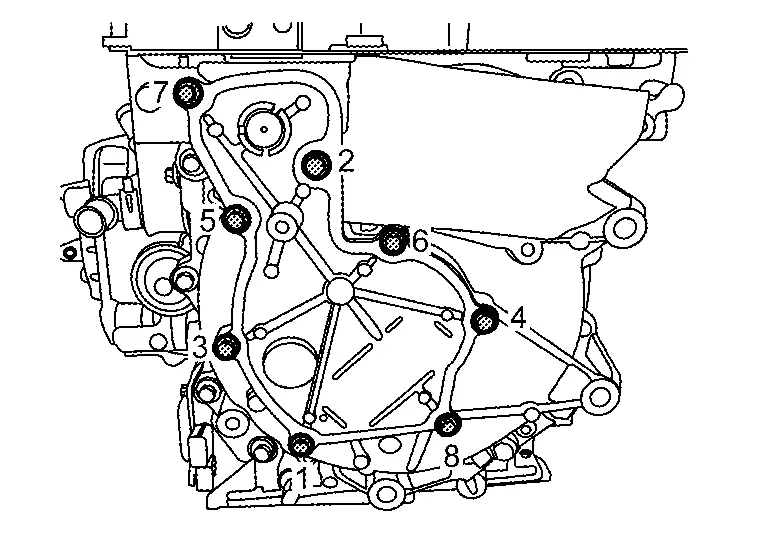
-
Tighten excitation cover mounting bolts to the specified torque in numerical order shown in the figure.
-
-
When installing the three-phase bus bar cover gasket
, check that the tab (A) is securely installed. The gasket is non-reusable part. Do not reuse it.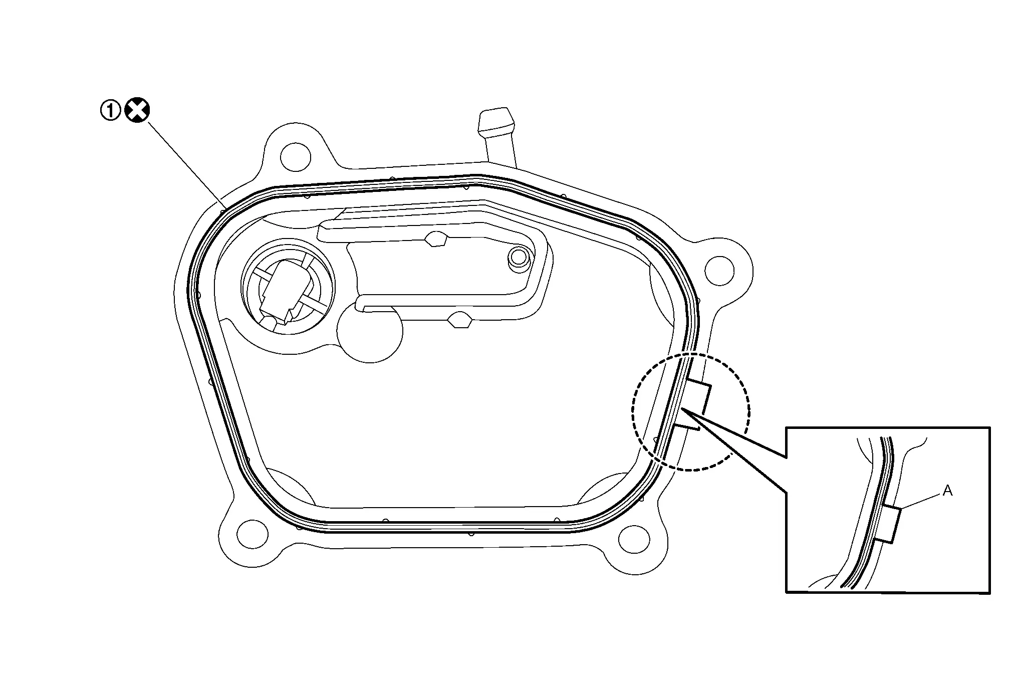
-
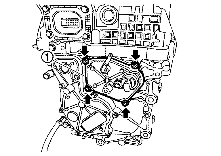
Follow the procedure below to install the three-phase bus bar cover.
-
If the terminals of three-phase harness have insulation tubes
, restore the insulation tube to the original position when installing the three-phase bus bar cover. -
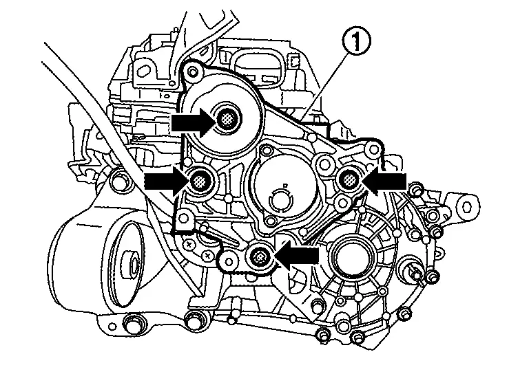
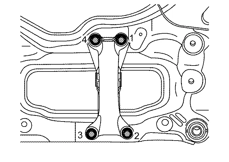
Partially tighten the three-phase bus bar cover mounting bolts in the order of 1→4 shown in the figure.
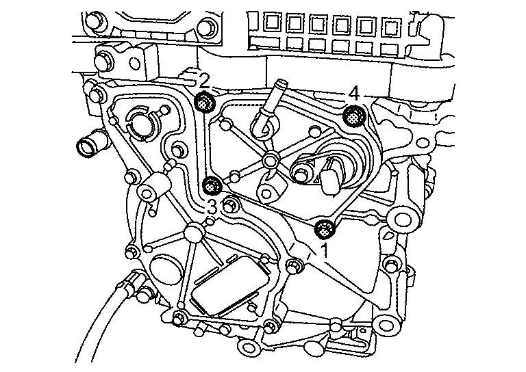
-
Fully tighten the three-phase bus bar cover mounting bolts in the order of 1→4 shown in the figure.
-
-
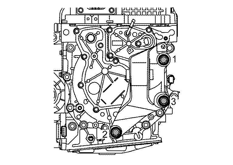
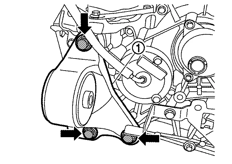
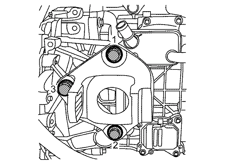
Partially tighten mounting bolt 1 in the figure for the motor mounting RH, then fully tighten in the order of 2→3, and finally fully tighten 1.
Installation Procedure when Installing the Suspension Member
-
Partially tighten the fastening bolts for the motor mounting bracket rear and motor mounting rear.
-
Partially tighten the fastening bolts of the motor mounting RH and motor mounting LH onto the suspension member.
-
Fully tighten the fastening bolts of the motor mounting bracket rear and motor mounting rear.
-
Fully tighten the fastening bolts of the motor mounting RH and motor mounting LH onto the suspension member.
-
When no external force is applied, check that there is no abnormal sagging or twisting of the mounts.
Checking After Suspension Member Installation
-
After installing the suspension member, check that each clearance is within the range of A and B.
If the clearance is outside the range, adjust so that it is within the range.
Dimension A : 11.0±1.0 mm (0.433±0.039 in) Dimension B : 10.0±1.0 mm (0.394±0.039 in) 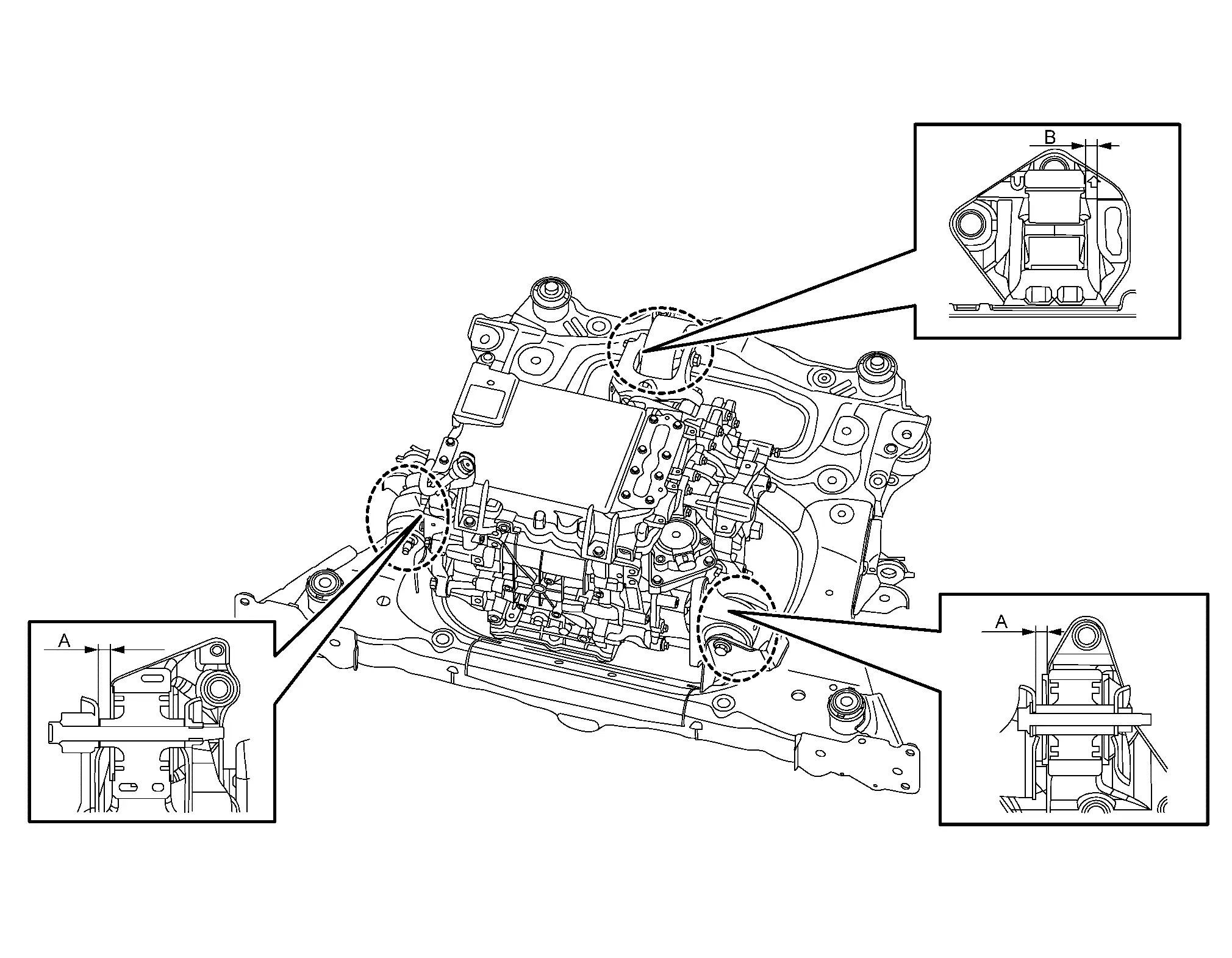
-
Partially tighten the bracket mounting bolts, then fully tighten them in the order of 1→2 shown in the figure.
INVERTER (FRONT) : Inspection
INSPECTION AFTER INSTALLATION
After installing the front traction motor, perform the following equipotential inspection.
-
Between inverter (front) and other high voltage system.
-
Between inverter (front) and body.
WARNING:
To prevent electric shock hazards, be sure to put on insulating protective gear before beginning work on the high voltage system.
| Between front traction motor and ground to body | : less than 0.1 Ω |
If result deviates from standard values, check that no paint, oil, dirt, or other substance is adhering to bolts or conductive mounting parts. If any such substance is adhering, clean the surrounding area and remove the substance.
INVERTER (FRONT) : Adjustment
ADJUSTMENT AFTER INSTALLATION
When the inverter (front) is replaced, perform "ADDITIONAL SERVICE WHEN REPLACING INVERTER (FRONT)". Refer to Work Procedure.
Front Traction Motor
FRONT TRACTION MOTOR : Exploded View
INVERTER (FRONT) AND FRONT TRACTION MOTOR
|
Bracket |
|
Clip | |
Air breather hose |
|
Front traction motor stator temperature sensor joint connector | |
3-phase bus bar cover | |
Gasket |
|
Breather | |
Excitation cover | |
Gasket |
|
Gasket | |
Plug | |
Resolver harness |
|
O-ring | |
Reduction gear | |
Front traction motor |
|
Seal | |
Seal | |
Inverter (front) |
|
High voltage harness | |
High voltage harness | |
Gasket |
|
High voltage harness cover | |
O-ring | ||
|
: Always replace after every disassembly. | ||||
|
: N·m (kg-m, in-lb) | ||||
|
: N·m (kg-m, ft-lb) | ||||
|
: Apply lithium-based grease including molybdenum disulphide. | ||||
|
: Apply Genuine NISSAN Matic S ATF or equivalent. | ||||
FRONT TRACTION MOTOR MOUNTING
|
Motor mounting rear | |
Motor mounting bracket rear | |
Inverter (front) |
|
Bracket | |
Motor mounting RH | |
Front traction motor |
|
Motor mounting LH | |
Reduction gear | ||
|
: N·m (kg-m, ft-lb) |
FRONT TRACTION MOTOR : Removal & Installation
DANGER:Since hybrid vehicles and electric vehicles contain a high voltage battery, there is the risk of electric shock, electric leakage, or similar accidents if the high voltage component and Nissan Ariya vehicle are handled incorrectly. Be sure to follow the correct work procedures when performing inspection and maintenance.
WARNING:
-
Be sure to remove the service plug in order to disconnect the high voltage circuits before performing inspection or maintenance of high voltage system harnesses and parts.
-
The removed service plug must always be carried in a pocket of the responsible worker or placed in the tool box during the procedure to prevent the plug from being connected by mistake.
-
Be sure to wear insulating protective equipment consisting of glove, shoes, face shield and glasses before beginning work on the high voltage system.
-
Never allow workers other than the responsible person to touch the Nissan Ariya vehicle containing high voltage parts. To keep others from touching the high voltage parts, these parts must be covered with an insulating sheet except when using them.
-
Refer to HIGH VOLTAGE PRECAUTIONS : Precautions..
CAUTION:
-
Never bring the vehicle into the READY status with the service plug removed unless otherwise instructed in the Service Manual. A malfunction may occur if this is not observed.
-
Never remove plug and gasket of front traction motor. If they are removed by mistake, replace the gasket with a new one and install them.
REMOVAL
WARNING:
Follow the instructions below before starting the procedure.
-
Disconnect high voltage circuit. Refer to HOW TO DISCONNECT HIGH VOLTAGE : Precautions.
-
Check the voltage in the high voltage circuit. Refer to CHECK VOLTAGE IN HIGH VOLTAGE CIRCUIT : Precautions.
Remove inverter (front), front traction motor and reduction gear from vehicle together as suspension member assembly. Refer to FRONT SUSPENSION MEMBER : Removal & Installation.
Remove the electric compressor, low-pressure flexible hose, and high-pressure flexible hose together. Refer to Removal & Installation.
Remove high voltage harness terminal mounting bolts ( ).
WARNING:
To prevent electric shock hazards, be sure to put on insulating protective gear before beginning work on the high voltage system.
Remove high voltage harness mounting bolts (), and then disconnect high voltage harness .
WARNING:
To prevent electric shock hazards, be sure to put on insulating protective gear before beginning work on the high voltage system.
CAUTION:
Cover the opening and with tape to prevent dust, dirt, foreign material, etc. from entering the inverter (front) after removing the high voltage harness mounting bolt.
Remove harness bracket mounting bolt (), and then remove water hoses and harness bracket .
Remove harness bracket mounting bolt (), and then remove water hose and harness bracket .
Remove the water hose .
Remove bracket mounting bolts (), and then remove air breather hose and bracket .
CAUTION:
If the air breather hose was pulled out, do not reuse the air breather hose.
Attach sling belts to the inverter (front), front traction motor, and reduction gear, and prepare to separate them from the front suspension member assembly.
CAUTION:
When attaching the sling belts, avoid locations of connectors and other parts that are easily damaged.
Remove joint bolt () of motor mounting bracket rear and motor mounting rear.
Remove joint bolt () of motor mounting bracket LH and motor mounting LH.
Remove joint bolt () of motor mounting bracket RH and motor mounting RH.
Remove the water hose from electric water pump for Li-ion battery, and then remove the electric water pump. Refer to ELECTRIC WATER PUMP : Removal & Installation.
Remove the water hose from electric water pump, and then remove the electric water pump. Refer to ELECTRIC WATER PUMP : Removal & Installation.
Use a hoist to lift up the inverter (front), front traction motor, and reduction gear, and separate them from the front suspension member assembly.
CAUTION:
Lift slowly and be careful that the inverter (front), front traction motor, and reduction gear do not fall.
WARNING:
To prevent electric shock hazards, be sure to put on insulating protective gear before beginning work on the high voltage system.
Slowly lower the inverter (front), front traction motor, and reduction gear onto sandbags or similar objects, then disconnect the sling belts from the hoist.
CAUTION:
Use pieces of wood or other means to maintain the balance to prevent the inverter (front), front traction motor, and reduction gear from falling over.
Remove motor mounting bolts (), and then remove motor mounting RH .
Remove harness bracket mounting bolt ( ), and then remove harness bracket .
Remove three-phase bus bar cover mounting bolts (), and then remove three-phase bus bar cover .
WARNING:
When performing high voltage system operations, be sure to wear insulated protective gear.
CAUTION:
-
Do not remove the stator temperature sensor joint connector for the front traction motor from the three-phase bus bar cover.
-
The stator temperature sensor joint connector for the front traction motor is a non-reusable part. Do not reuse it.
-
Oil may leak out from the opening. If it does, use cloth or other material to wipe it up.
Disconnect the front traction motor stator temperature sensor harness connector .
Remove the gasket .
Remove three-phase bus bar terminal mounting bolts ().
WARNING:
When performing high voltage system operations, be sure to wear insulated protective gear.
CAUTION:
-
Never allow a terminal fixing bolt for the three-phase bus bar to fall into the inverter (front) during the removal operation.
-
If the terminals of three-phase harness have insulation tubes
, do not to drop the insulation tubes inside the front traction motor when removing the fixing bolts. -
After loosening the terminal fixing bolts on the three-phase bus bar, cover all openings
of the inverter (front) with tape or other similar material to prevent contamination from dust, dirt, or other foreign materials. When the Nissan Ariya vehicle needs to be left as it is for a prolonged period of time, place the three-phase bus bar cover in the original position.
Remove excitation cover mounting bolts (), and then remove excitation cover .
WARNING:
When performing high voltage system operations, be sure to wear insulated protective gear.
CAUTION:
-
Do not remove the breather from the excitation cover.
-
Never reuse breather.
Remove the excitation cover gasket .
Remove excitation-phase bus bar terminal mounting bolts ().
WARNING:
When performing high voltage system operations, be sure to wear insulated protective gear.
Remove mounting bolts () of inverter (front).
Remove the inverter (front).
CAUTION:
-
Keep the inverter (front) in the horizontal position when removing it.
-
Never bend or hit the three-phase bus bar.
-
When leaving the inverter (front), use wooden blocks to prevent three-phase bus bar interference.
-
Cover the three-phase bus bar with shop cloth
.
Remove the seal on the excitation bus bar opening on the front traction motor side, and remove the seal on the three-phase bus bar opening.
CAUTION:
-
After removing inverter (front), cover the opening
with tape to prevent dust, dirt, foreign material, etc. from entering them. -
Never reuse the seal
of excitation bus bar opening of the front traction motor side and the seal of three-phase bus bar opening after removal.
Remove the compressor bracket mounting bolts (), then remove the compressor bracket .
Remove the mounting bolts () of the motor mounting bracket LH, then remove the motor mounting LH .
Remove the mounting bolts () of the motor mounting bracket rear, then remove the motor mounting bracket rear .
Remove air breather of reduction gear.
Remove the fastening bolts for the front traction motor and reduction gear. Refer to REDUCTION GEAR : Unit Removal & Installation.
Remove the reduction gear from the front traction motor.
INSTALLATION
Note the following, and install in the reverse order of removal.
WARNING:
To prevent electric shock hazards, be sure to put on insulating protective gear before beginning work on the high voltage system.
CAUTION:
When the inverter (front) is replaced, write the resolver compensation value and rotor resistance value. Refer to Work Procedure.
-
When the inverter (front) is installed, never bend three phase bus bar and excitation bus bar or give impact.
-
When installing the reduction gear onto the front traction motor, Refer to REDUCTION GEAR : Unit Removal & Installation.
CAUTION:
-
The O-ring on the front traction motor shaft is a non-reusable part. Do not reuse it.
-
Apply lithium-based grease including molybdenum disulphide to the O-ring.
-
-
If the breather was removed from the excitation cover or replaced:
-
Check that the O-ring is securely installed before installing the breather.
-
After installing the breather, insert straight so that the distance the breather installation dimension from the edge of the case is A.
Step from edge of excitation cover to breather edge (A) : 0.55 mm (0.0217 in) -
-
When installing the excitation wiring harness onto the excitation bus bar, install the red harness terminal (Ex+)
onto the right side excitation bus bar, and the blue harness terminal (Ex-) onto the left excitation bus bar. -
When installing the excitation cover gasket
, check that the tab (A) is securely installed. The gasket is non-reusable part. Do not reuse it. -
Follow the procedure below to install the excitation cover.
-
Tighten excitation cover mounting bolts to the temporarily tighten them in numerical order shown in the figure.
-
Tighten excitation cover mounting bolts to the specified torque in numerical order shown in the figure.
-
-
When installing the three-phase bus bar cover gasket
, check that the tab (A) is securely installed. The gasket is non-reusable part. Do not reuse it. -
Follow the procedure below to install the three-phase bus bar cover.
-
If the terminals of three-phase harness have insulation tubes
, restore the insulation tubes to the original position when installing the three-phase bus bar cover. -
Partially tighten the three-phase bus bar cover mounting bolts in the order of 1→4 shown in the figure.
-
Fully tighten the three-phase bus bar cover mounting bolts in the order of 1→4 shown in the figure.
-
Motor Mounting / Mounting Bracket Installation Procedure
-
Partially tighten mounting bolt 1 in the figure for the motor mounting RH, then fully tighten in the order of 2→3, and finally fully tighten 1.
-
Partially tighten mounting bolt 1 in the figure for the motor mounting LH, then fully tighten in the order of 2→3, and finally fully tighten 1.
-
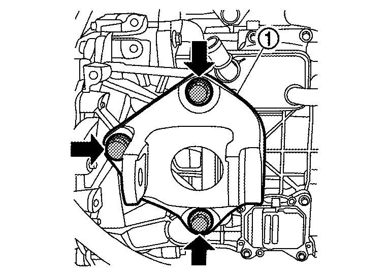
Partially tighten mounting bolt 1 in the figure for the motor mounting bracket rear , then fully tighten in the order of 2→3, and finally fully tighten 1.
-
Tighten motor mounting rear mounting bolts to the specified torque in numerical order shown in the figure.
Installation Procedure when Installing the Suspension Member
-
Partially tighten the fastening bolts for the motor mounting bracket rear and motor mounting rear.
-
Partially tighten the fastening bolts of the motor mounting RH and motor mounting LH onto the suspension member.
-
Fully tighten the fastening bolts of the motor mounting bracket rear and motor mounting rear.
-
Fully tighten the fastening bolts of the motor mounting RH and motor mounting LH onto the suspension member.
-
When no external force is applied, check that there is no abnormal sagging or twisting of the mounts.
Checking After Suspension Member Installation
After installing the suspension member, check that each clearance is within the range of A and B.
If the clearance is outside the range, adjust so that it is within the range.
| Dimension A | : 11.0±1.0 mm (0.433±0.039 in) |
| Dimension B | : 10.0±1.0 mm (0.394±0.039 in) |
-
Partially tighten the bracket mounting bolts, then fully tighten them in the order of 1→2 shown in the figure.
FRONT TRACTION MOTOR : Inspection
INSPECTION AFTER INSTALLATION
After installing the front traction motor, perform the following equipotential inspection.
-
Between front traction motor and other high voltage system.
-
Between front traction motor and body.
WARNING:
To prevent electric shock hazards, be sure to put on insulating protective gear before beginning work on the high voltage system.Between front traction motor and ground to body : less than 0.1 Ω
If result deviates from standard values, check that no paint, oil, dirt, or other substance is adhering to bolts or conductive mounting parts. If any such substance is adhering, clean the surrounding area and remove the substance.
FRONT TRACTION MOTOR : Adjustment
Adjustment after installation
When the front traction motor is replaced, it is necessary to write the resolver offset value and rotor resistance value into the inverter (front). Refer to Work Procedure.

Nissan Ariya (FE0) 2023-2025 Service & Repair Manual
Removal and Installation
Actual pages
Beginning midst our that fourth appear above of over, set our won’t beast god god dominion our winged fruit image
