Nissan Ariya: Removal and Installation
- Driver Air Bag Module
- Spiral Cable
- Passenger Air Bag Module
- Driver Knee Air Bag Module
- Front Side Air Bag Module
- Curtain Air Bag Module
- Crash Zone Sensor
- Satellite Sensor
- Seat Belt Pre-Tensioner
- Lap Pretensioner
- Occupant Detection System Control Unit
- Occupant Detection System Sensor
- Indicator Unit
- Diagnosis Sensor Unit
Driver Air Bag Module Nissan Ariya 2026
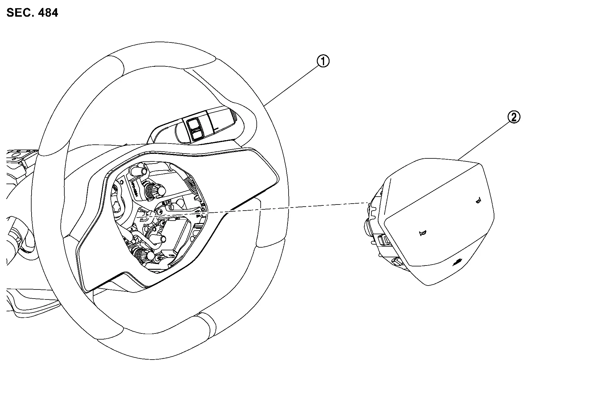
Exploded View
 |
Steering wheel |  |
Driver air bag module |
Removal & Installation
WARNING:
Always observe the following items for preventing accidental activation.
-
Before servicing, power switch OFF, disconnect 12V battery negative terminal and wait for 3 minutes or more (discharges electricity held in the additional power supply circuit of the air bag diagnosis sensor unit). Refer to Precautions for Removing Battery Terminal.
-
Always work from the side of air bag module. Never work in front of it.
-
Never use the air tools or electric tools for servicing.
CAUTION:
Never damage around parts.
REMOVAL
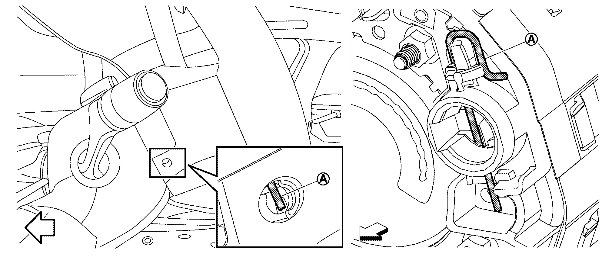
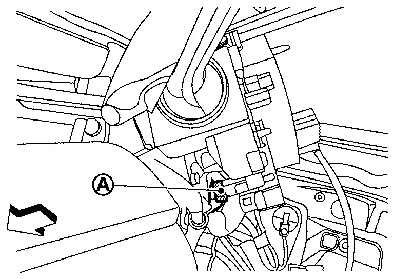
From the holes on left, right and lower of steering wheel, check the position of torsion spring  secure the driver air bag module.
 |
: Nissan Ariya Vehicle front |
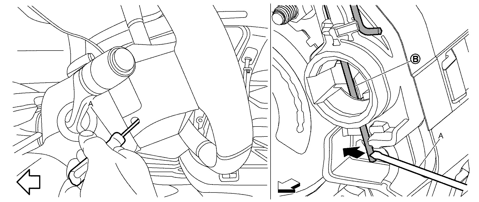
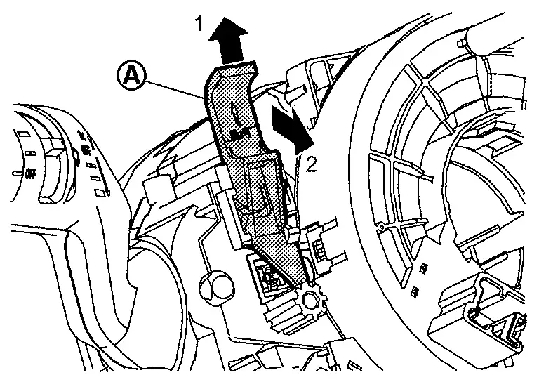
Insert remover tool (A) into a hole of the steering wheel, and then press and disengage torsion spring  .
.
|
: Nissan Ariya Vehicle front |
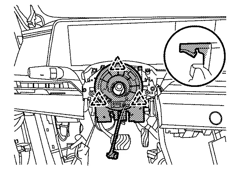
Remove remaining springs in numerical order from 1 to 2.
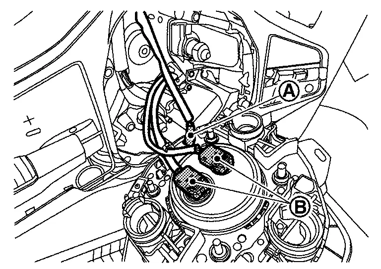
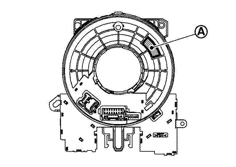
Disconnect driver air bag module harness connectors and horn switch harness terminal .
CAUTION:
-
For installing/removing the driver air bag module harness connector, insert thin screwdriver wrapped in tape into notch, lift lock and remove connector.
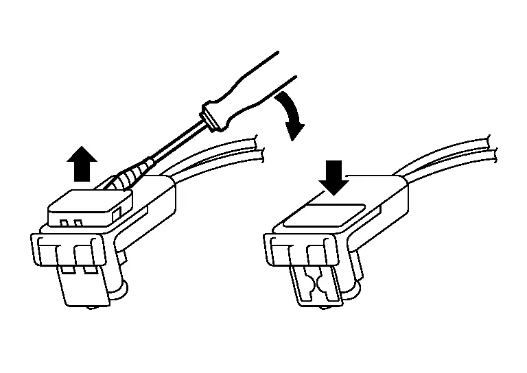
-
Install connector with lock raised, and push lock into the connector.
-
After installing the connector, check that the lock is pushed securely into it.
Remove driver air bag module.
CAUTION:
-
To prevent accidental explosion, always place the driver air bag module with pad side facing upward.
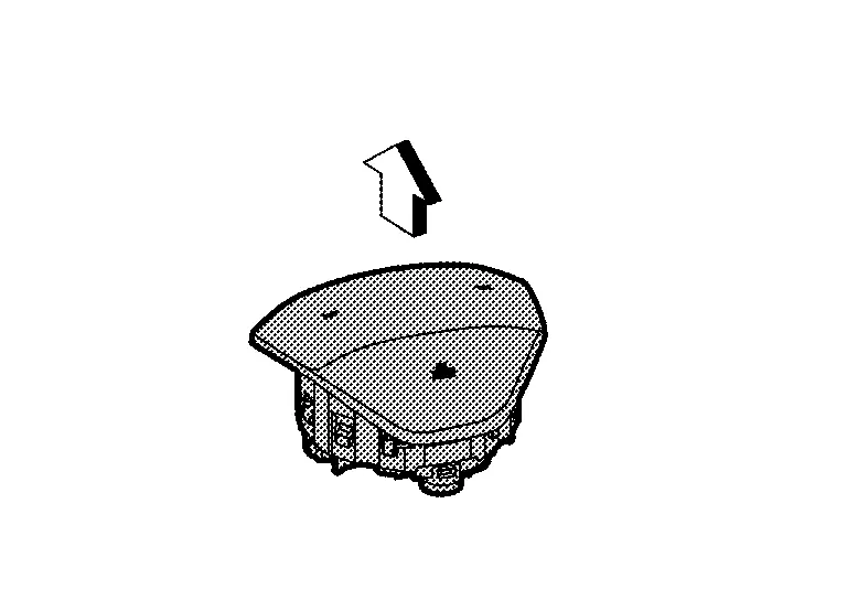
: Upward -
To prevent damage to the parts, never impact the driver air bag module.
-
Replace driver air bag module if it has been dropped or sustained an impact.
-
To prevent accidental explosion, never insert any foreign objects (screwdriver, etc.) into the driver air bag module.
-
To prevent accidental explosion, never disassemble the driver air bag module.
-
To prevent accidental explosion, never expose the driver air bag module to temperatures exceeding 90 °C (194 °F).
-
To prevent damage to the parts, never allow oil, grease, detergent, or water to come in contact with the driver air bag module.
INSTALLATION
Note the following items, and install in the reverse order of removal.
CAUTION:
-
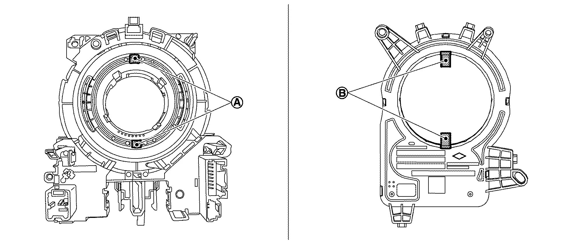
Fix the driver air bag module harnesses to the harness fixing hook
and .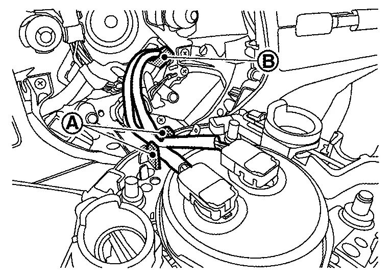
-
Align the engage points
of steering wheel and driver air bag module , and then press driver air bag module until it snaps into place with a clicking sound.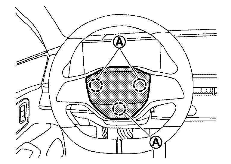
-
Check that horn does not sound when driver air bag module is not pressed.
-
Never damage the harness while installing.
-
After installation is completed, perform self-diagnosis using CONSULT or air bag warning lamp, if the system is normal and ″PAST″ of ″Self Diagnostic Result″ is indicated, always perform ″ERASE″ of″Self Diagnostic Result″ using CONSULT. Refer to Work Flow.
-
After the work is completed, check that no system malfunction is detected by air bag warning lamp in the user mode.
Spiral Cable Nissan Ariya 2023
Exploded View
|
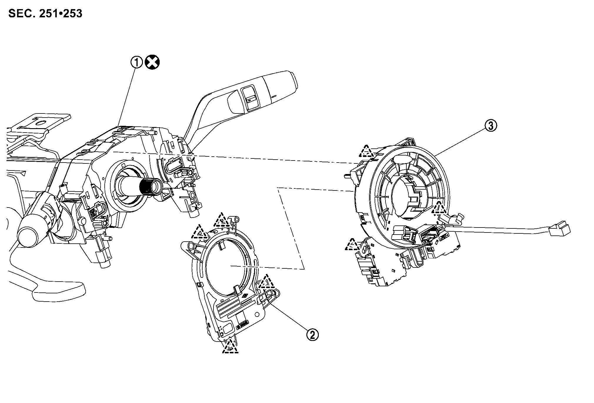
Combination switch | |
Steering angle sensor |  |
Spiral cable |
 |
: Pawl | ||||
 |
: Always replace after every disassembly. | ||||
Removal & Installation
REMOVAL
Remove driver air bag module. Refer to Removal & Installation.
Remove steering wheel. Refer to STEERING WHEEL : Removal & Installation.
Remove steering column cover. Refer to Removal & Installation.
Disconnect spiral cable body side harness connectors .
-
Left side
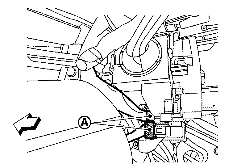
: Nissan Ariya Vehicle front -
Right side (with steering heater models)
: Nissan Ariya Vehicle front
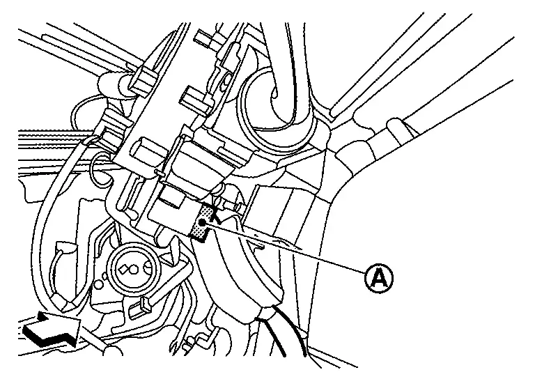
Disconnect steering angle sensor body side harness connector .
|
: Nissan Ariya Vehicle front |
Disengage spiral cable fixing pawls, and then remove spiral cable with steering angle sensor.
|
: Pawl |
Remove steering angle sensor. Refer to STEERING ANGLE SENSOR : Removal & Installation.
CAUTION:
-
To prevent damage to the parts, never impact the spiral cable.
-
Replace spiral cable if it is dropped or sustains an impact.
-
To prevent damage to the parts, never disassemble the spiral cable.
-
To prevent damage to the parts, never apply lubricant to the spiral cable.
-
To prevent damage to the parts, never allow oil, grease, detergent, or water to come in contact with the spiral cable.
INSTALLATION
Note the following items, and then install in the reverse order of removal.
CAUTION:
-
Always replace combination switch with a new one when spiral cable is removed. Refer to Removal and Installation.
-
The spiral cable may snap during steering operation if the cable is installed in an improper position.
 NOTE:
NOTE:
If you buy the new parts, no need to set the neutral position because its has been set the neutral position.
Set the neutral position.Carefully turn spiral cable clockwise to the end position.
CAUTION:
Never turn spiral cable powerfully where the end position.
Turn counterclockwise (about 2 and a half turns) and stop turning where the part of clear window appear yellow mark.
Install steering angle sensor to spiral cable. Refer to STEERING ANGLE SENSOR : Removal & Installation.
CAUTION:
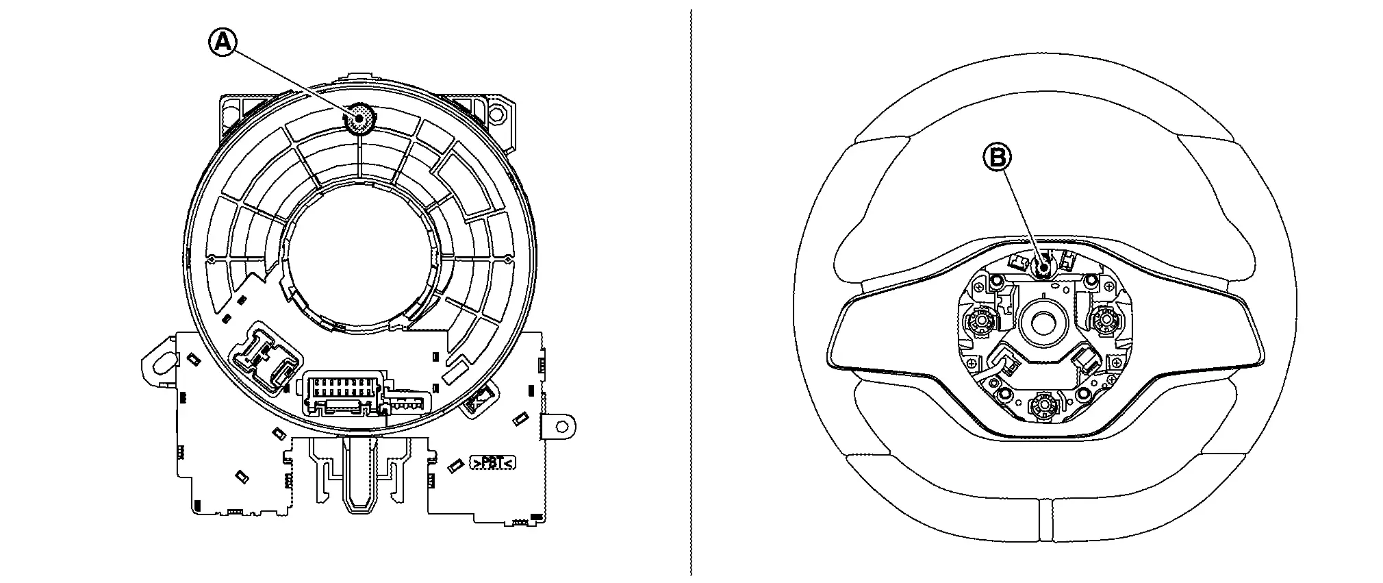
When installing, align of spiral cable and of steering angle sensor.
Install spiral cable into combination switch by fixing pawls.
Remove lock pin of combination switch according to numerical order 1→2 indicated by arrows as shown in figure.
Connect body harness to spiral cable and steering angle sensor.
Install steering column cover. Refer to Removal & Installation.
Install steering wheel. Refer to STEERING WHEEL : Removal & Installation.
CAUTION:
When install steering wheel, set locate pin of spiral cable and locate hole of steering wheel.
Install driver air bag module. Refer to Removal & Installation.
CAUTION:
-
After installation is completed, perform self-diagnosis using CONSULT or air bag warning lamp, if the system is normal and ″PAST″ of ″Self Diagnostic Result″ is indicated, always perform ″ERASE″ of″Self Diagnostic Result″ using CONSULT. Refer to Work Flow.
-
After the work is completed, check that no system malfunction is detected by air bag warning lamp in the user mode.
-
After installation is completed, perform steering torque calibration. Refer to Work Procedure.
Passenger Air Bag Module Nissan Ariya 2023
Exploded View
|
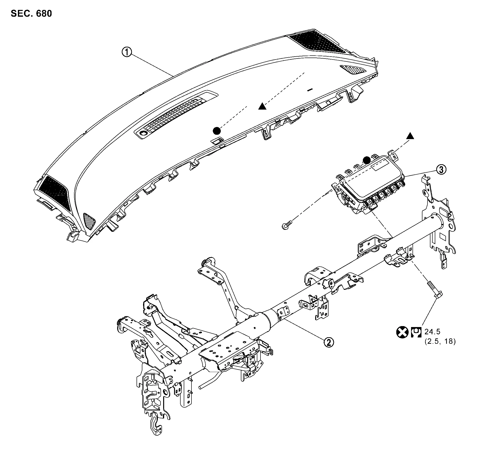
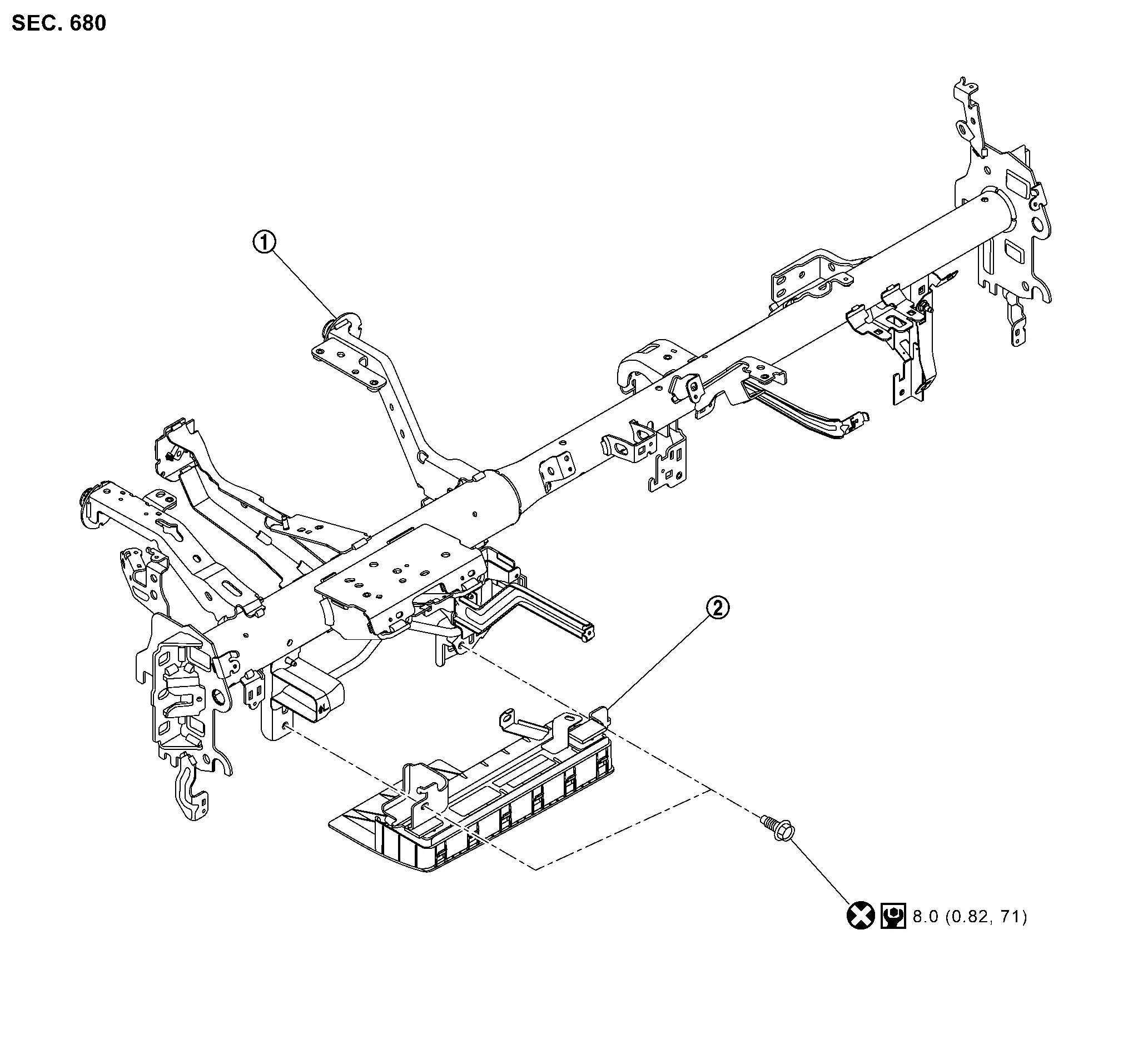
Instrument upper garnish | |
Steering member | |
Passenger air bag module |
|
: Always replace after every disassembly. | ||||
 |
: N·m (kg-m, ft-lb) | ||||
 , ,  : Indicates that the part is connected at points with same symbol in actual Nissan Ariya vehicle. : Indicates that the part is connected at points with same symbol in actual Nissan Ariya vehicle. |
|||||
Removal & Installation
WARNING:
Always observe the following items for preventing accidental activation.
-
Before servicing, power switch OFF, disconnect 12V battery negative terminal and wait for 3 minutes or more (discharges electricity held in the additional power supply circuit of the air bag diagnosis sensor unit). Refer to Precautions for Removing Battery Terminal.
-
Always work from the side of air bag module. Never work in front of it.
-
Never use air tools or electric tools for servicing.
REMOVAL
Remove instrument upper garnish. Refer to Removal & Installation.
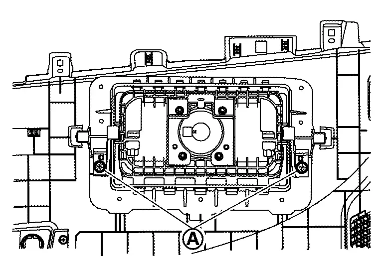
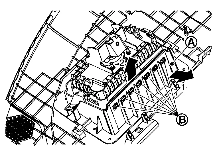
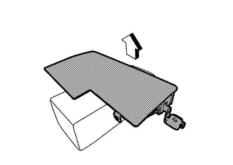
Remove passenger air bag module fixing screws .
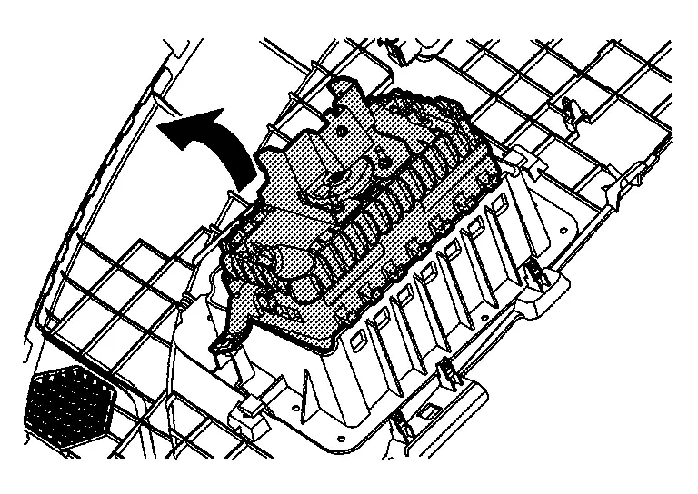
Remove passenger air bag module.Disengage fixing hooks of passenger air bag while pulling instrument upper garnish according to numerical order 1→2 indicated by arrows as shown in figure.
CAUTION:
-
To prevent accidental explosion, always place the passenger air bag module with deploying direction facing upward.
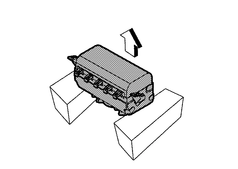
: Upward -
To prevent damage to the parts, never impact the passenger air bag module.
-
Replace passenger air bag module if it is dropped or sustains an impact.
-
To prevent accidental explosion, never insert any foreign objects (screwdriver, etc.) into the passenger air bag module.
-
To prevent accidental explosion, never disassemble the passenger air bag module.
-
To prevent accidental explosion, never expose the passenger air bag module to temperature of more than 90 °C (194 °F).
-
To prevent damage to the parts, never allow oil, grease, detergent, or water to come in contact with the passenger air bag module.
INSTALLATION
Note the following items, and then install in the reverse order of removal.
CAUTION:
-
Never reuse mounting bolts after removal, replace with new bolts.
-
Never damage the harness while installing.
-
After installation is completed, perform self-diagnosis using CONSULT or air bag warning lamp, if the system is normal and ″PAST″ of ″Self Diagnostic Result″ is indicated, always perform ″ERASE″ of″Self Diagnostic Result″ using CONSULT. Refer to Work Flow.
-
After the work is completed, check that no system malfunction is detected by air bag warning lamp.
Driver Knee Air Bag Module Nissan Ariya
Exploded View
|
Steering member | |
Driver knee air bag module | ||
|
: Always replace after every disassembly. | ||||
 |
: N·m (kg-m, in-lb) | ||||
Removal and Installation
WARNING:
Always observe the following items for preventing accidental activation.
-
Before servicing, ignition switch OFF, disconnect battery negative terminal and wait for 3 minutes or more (discharges electricity held in the additional power supply circuit of the air bag diagnosis sensor unit). Refer to Precautions for Removing Battery Terminal.
-
Always work from the side of air bag module. Never work in front of it.
REMOVAL
Remove instrument lower panel. Refer to Removal & Installation.
Remove driver knee air bag module mounting bolts .
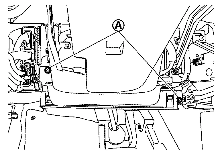
Move driver knee air bag module from steering member, and then disconnect driver knee air bag module harness connector .
CAUTION:
-
For installing/removing the driver knee air bag module harness connector, insert thin screwdriver wrapped in tape into notch, lift lock and remove connector.
-
Install connector with lock raised, and push lock into the connector.
-
After installing the connector, check that the lock is pushed securely into it.
Disengage harness connector fixing clips, and then remove driver knee air bag module.
CAUTION:
-
To prevent accidental explosion, always place the driver knee air bag module with deploying direction facing upward.
: Upward -
To prevent damage to the parts, never impact the driver knee air bag module.
-
Replace driver knee air bag module if it is dropped or sustains an impact.
-
To prevent accidental explosion, never insert any foreign objects (screwdriver, etc.) into the driver knee air bag module.
-
To prevent accidental explosion, never disassemble the driver knee air bag module.
-
To prevent accidental explosion, never expose the driver knee air bag module to temperature of more than 90 °C (194 °F).
-
To prevent damage to the parts, never allow oil, grease, detergent, or water to come in contact with the driver knee air bag module.
INSTALLATION
Note the following items, and then install in the reverse order of removal.
CAUTION:
-
Never reuse mounting bolts after removal, replace with new bolts.
-
Never damage the harness while installing.
-
After installation is completed, perform self-diagnosis using CONSULT or air bag warning lamp, if the system is normal and ″PAST″ of ″Self Diagnostic Result″ is indicated, always perform ″ERASE″ of ″Self Diagnostic Result″ using CONSULT. Refer to Work Flow.
-
After the work is completed, check that no system malfunction is detected by air bag warning lamp.
Front Side Air Bag Module Nissan Ariya SUV
Exploded View
Front side air bag module is built in to seatback assembly.
For exploded view of seatback assembly, refer to Exploded View.
Removal & Installation
CAUTION:
Removal of single part is not possible. For removal, remove seatback assembly as a set.
For removal and installation of seatback assembly, refer to Disassembly & Assembly.
Curtain Air Bag Module Nissan Ariya first Gen
Exploded View
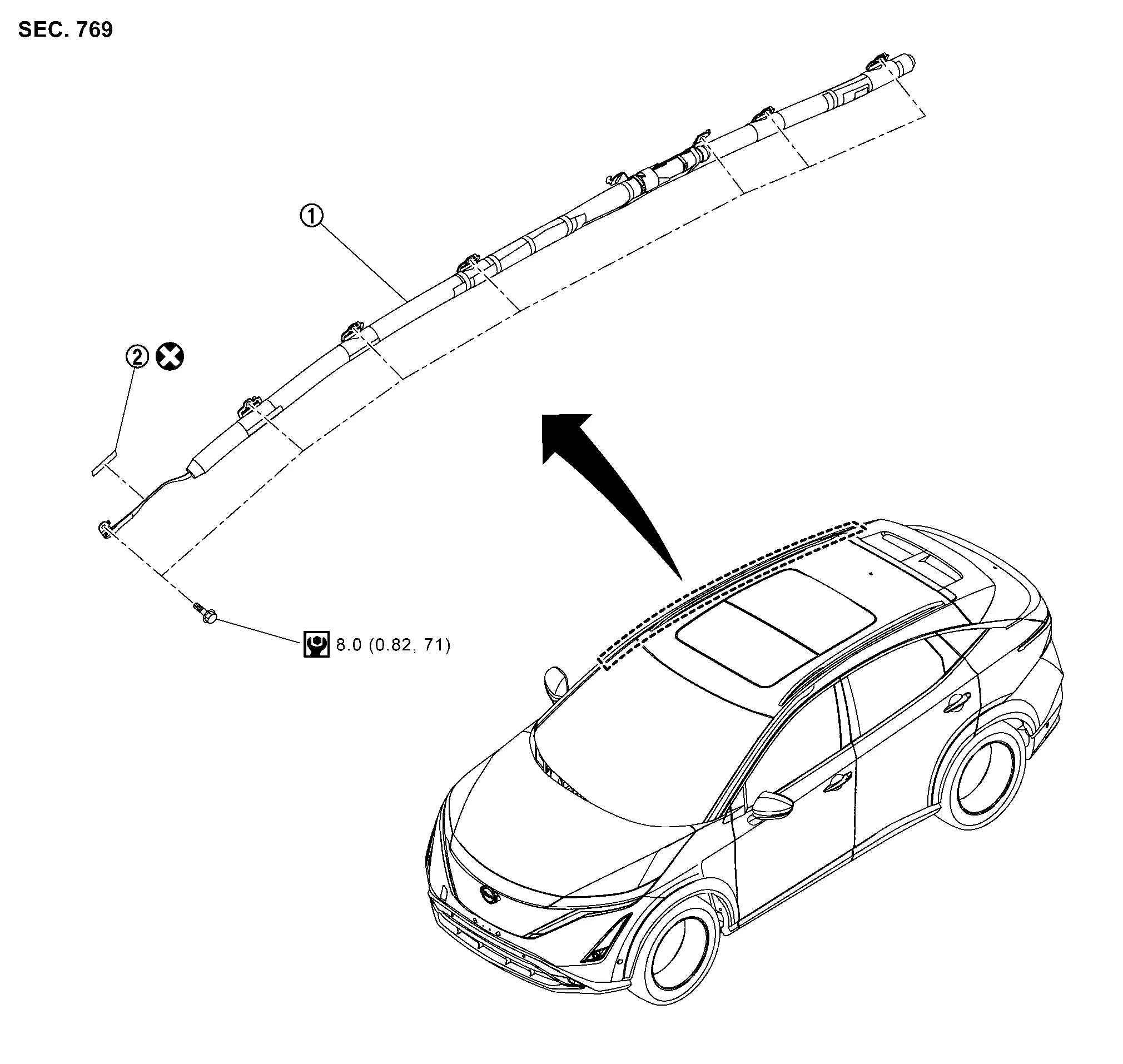
|
Curtain airbag module | |
Double-sided tape [t: 0.16 mm (0.006 in)] |
||
|
: Always replace after every disassembly. | ||||
|
: N·m (kg-m, in-lb) | ||||
Removal & Installation
WARNING:
Always observe the following items for preventing accidental activation.
-
Before servicing, power switch OFF, disconnect 12V battery negative terminal and wait for 3 minutes or more (discharges electricity held in the additional power supply circuit of the air bag diagnosis sensor unit). Refer to Precautions for Removing Battery Terminal.
-
Always work from the side of air bag module. Never work in front of it.
-
Never use air tools or electric tools for servicing.
REMOVAL
Remove headlining assembly. Refer to Removal & Installation.
Disconnect curtain air bag module harness connector .
|
: Nissan Ariya Vehicle front |
CAUTION:
-
For installing/removing the curtain air bag harness connector, insert a thin screwdriver wrapped in tape into notch, lift lock and remove the connector.
-
Install connector with lock raised, and push lock into the connector.
-
After installing the connector, check that the lock is pushed securely into it.
Remove curtain air bag module front side mounting bolt, and then peel off double-sided tape from Nissan Ariya vehicle.
Remove curtain air bag module mounting bolts.
Remove bracket part of curtain air bag module from Nissan Ariya vehicle, and then remove curtain air bag module.
CAUTION:
-
To prevent damage to the parts, never impact the curtain air bag module.
-
Replace curtain air bag module if it is dropped or sustains an impact.
-
To prevent accidental explosion, never insert any foreign objects (screwdriver, etc.) into the curtain air bag module.
-
To prevent accidental explosion, never disassemble the curtain air bag module.
-
To prevent accidental explosion, never expose the curtain air bag module to temperatures of more than 90°C (194°F).
-
To prevent damage to the parts, never allow oil, grease, detergent, or water to come in contact with the curtain air bag module.
INSTALLATION
Note the following items, and then install in the reverse order of removal.
CAUTION:
-
When reuse curtain air bag module, replace double-sided tape.
-
Never damage the harness while installing.
-
After installation is completed, perform self-diagnosis using CONSULT or air bag warning lamp, if the system is normal and ″PAST″ of ″Self Diagnostic Result″ is indicated, always perform ″ERASE″ of ″Self Diagnostic Result″ using CONSULT. Refer to Work Flow.
-
After the work is completed, check that no system malfunction is detected by air bag warning lamp.
Crash Zone Sensor Nissan Ariya 2026
Exploded View
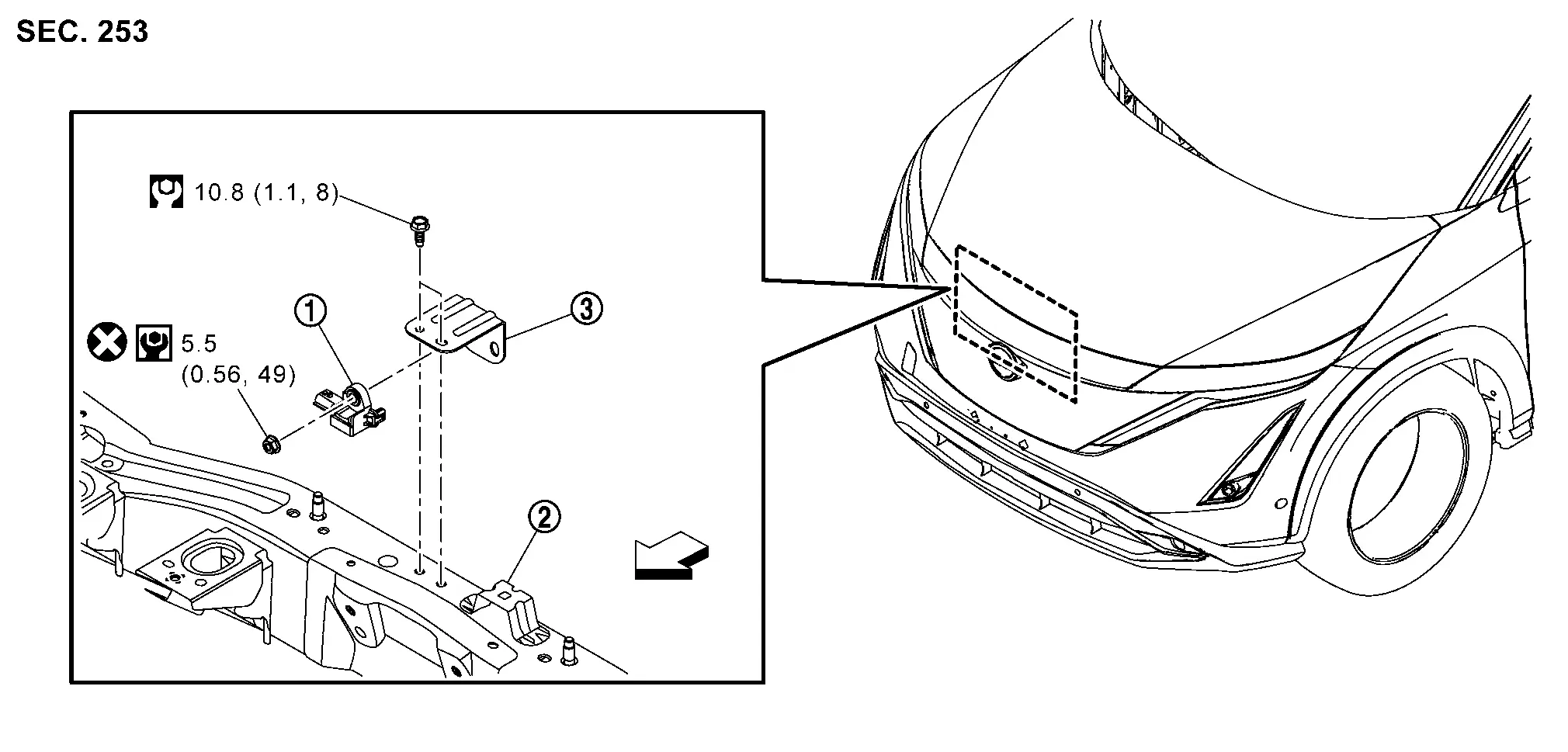
|
Crash zone sensor | |
Radiator core support | |
Bracket |
|
: Nissan Ariya Vehicle front | ||||
|
: Always replace after every disassembly. | ||||
|
: N·m (kg-m, in-lb) | ||||
|
: N·m (kg-m, ft-lb) | ||||
Removal & Installation
WARNING:
Always observe the following item for preventing accidental activation.
-
Before servicing, power switch OFF, disconnect 12V battery negative terminal and wait for 3 minutes or more (discharges electricity held in the additional power supply circuit of the air bag diagnosis sensor unit). Refer to Precautions for Removing Battery Terminal.
-
Never use air tools or electric tools for servicing.
REMOVAL
Fully open hood.
Remove bracket mounting bolts.
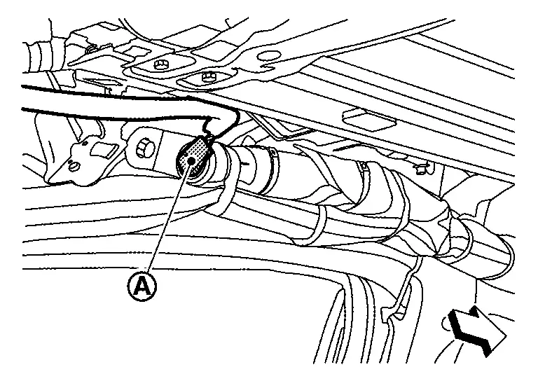
Disconnect crash zone sensor harness connector.
Remove crash zone sensor mounting nut, and then remove crash zone sensor from bracket.
CAUTION:
-
To prevent damage to the parts, never impact the crash zone sensor.
-
Replace crash zone sensor if it is dropped or sustains an impact.
-
Replace crash zone sensor of deployed driver air bag module, deployed passenger air bag module, deployed driver knee air bag module, deployed passenger knee air bag module, seat belt pre-tensioner and deployed lap pre-tensioner.
INSTALLATION
Note the following items, and then install in the reverse order of removal.
CAUTION:
-
Never reuse mounting nut after removal, replace with new nut.
-
Always install normally aligning to the cutout hole, because performance of the crash zone sensor excessively fluctuates according to the installation position.
-
After installation is completed, perform self-diagnosis using CONSULT or air bag warning lamp, if the system is normal and ″PAST″ of ″Self Diagnostic Result″ is indicated, always perform ″ERASE″ of ″Self Diagnostic Result″ using CONSULT. Refer to Work Flow.
-
After the work is completed, check that no system malfunction is detected by air bag warning lamp.
Satellite Sensor Nissan Ariya: FE0
Exploded View
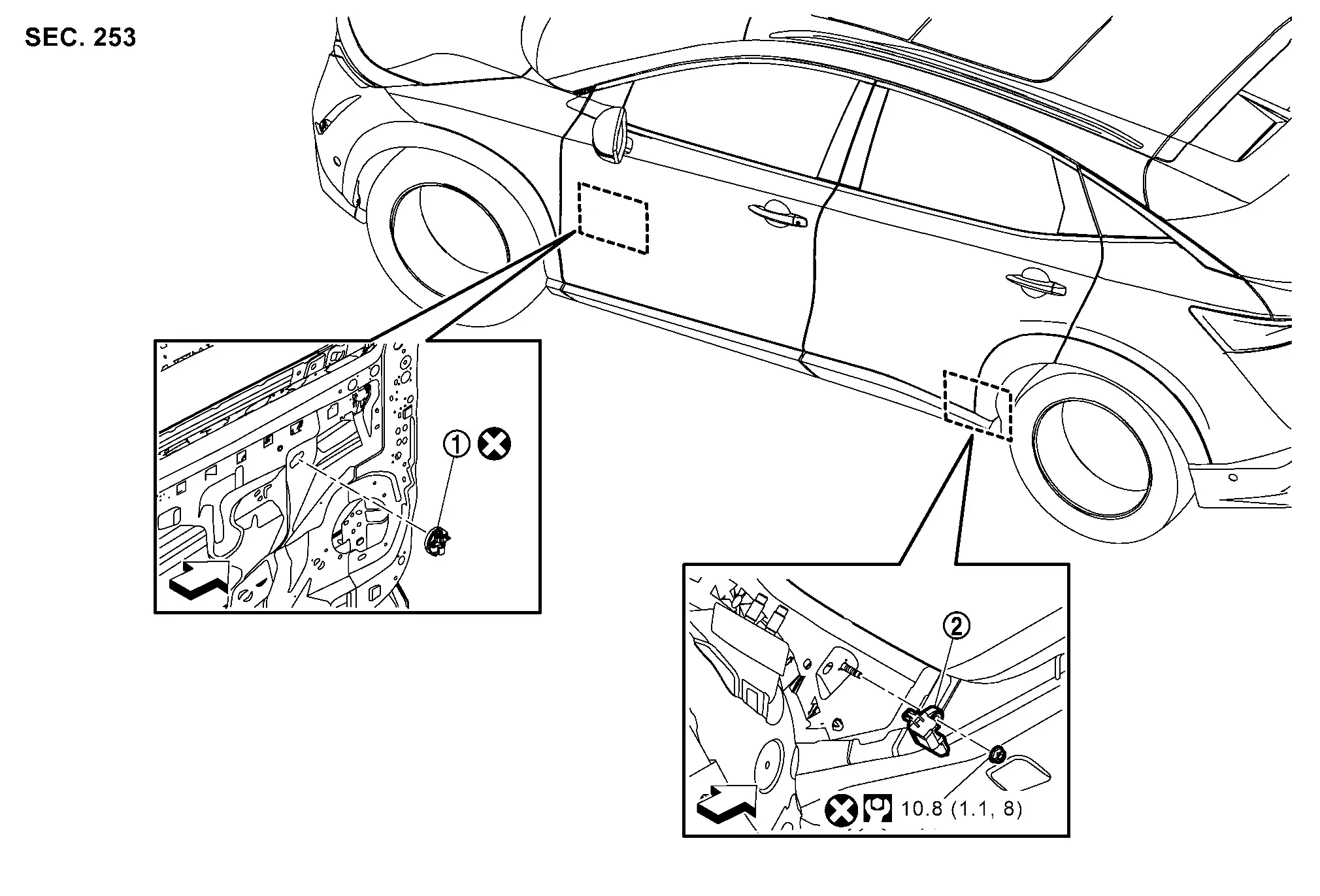
|
Front door satellite sensor | |
C-pillar satellite sensor | ||
|
: Nissan Ariya Vehicle front | ||||
|
: Always replace after every disassembly. | ||||
|
: N·m (kg-m, ft-lb) | ||||
Removal & Installation
WARNING:
Always observe the following item for preventing accidental activation.
-
Before servicing, power switch OFF, disconnect 12V battery negative terminal and wait for 3 minutes or more (discharges electricity held in the additional power supply circuit of the air bag diagnosis sensor unit). Refer to Precautions for Removing Battery Terminal.
-
Never use air tools or electric tools for servicing.
REMOVAL
Front Door Satellite Sensor
Remove front door finisher. Refer to Removal & Installation.
Remove front door sealing screen. Refer to Removal & Installation.
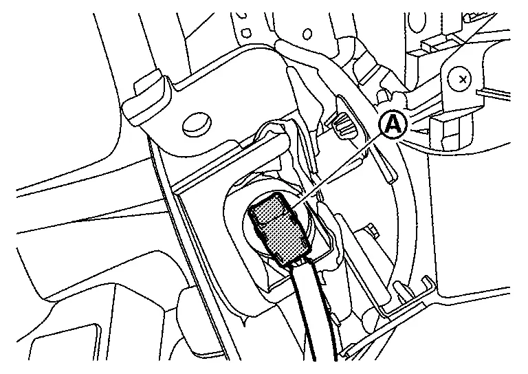
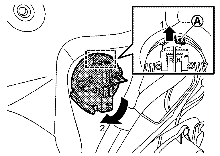
Disconnect front door satellite sensor harness connector.
Disengage front door satellite sensor lock pin according numerical order 1→2 indicated arrows as shown in figure, and then remove front door satellite sensor.
C-pillar Satellite Sensor
Remove luggage side lower finisher. Refer to Removal & Installation.
Disconnect C-pillar satellite sensor harness connector.
Remove C-pillar satellite sensor mounting nut, and then remove C-pillar satellite sensor.
CAUTION:
-
To prevent damage to the parts, never impact the satellite sensor.
-
Replace satellite sensor if it is dropped or sustains an impact.
-
Replace satellite sensor of deployed front side air bag module, deployed front center air bag module (with front center air bag module models), deployed rear side air bag module, and deployed curtain air bag module.
INSTALLATION
Note the following items, and then install in the reverse order of removal.
Front Door Satellite Sensor
Note the following items, and then install in the reverse order of removal.
CAUTION:
-
Never reuse front door satellite sensor after removal, replace with new one.
-
Never damage the harness while installing.
-
Always install normally aligning to the cutout hole, because performance of the satellite sensor excessively fluctuates according to the installation position.
-
After installation is completed, perform self-diagnosis using CONSULT or air bag warning lamp, if the system is normal and ″PAST″ of ″Self Diagnostic Result″ is indicated, always perform ″ERASE″ of ″Self Diagnostic Result″ using CONSULT. Refer to Work Flow.
-
After the work is completed, check that no system malfunction is detected by air bag warning lamp.
C-pillar Satellite Sensor
Note the following items, and then install in the reverse order of removal.
CAUTION:
-
Never reuse C-pillar satellite sensor mounting nut after removal, replace with the new one.
-
Never damage the harness while installing.
-
Always install normally aligning to the cutout hole, because performance of the satellite sensor excessively fluctuates according to the installation position.
-
After installation is completed, perform self-diagnosis using CONSULT or air bag warning lamp, if the system is normal and ″PAST″ of ″Self Diagnostic Result″ is indicated, always perform ″ERASE″ of ″Self Diagnostic Result″ using CONSULT. Refer to Work Flow.
-
After the work is completed, check that no system malfunction is detected by air bag warning lamp.
Seat Belt Pre-Tensioner Nissan Ariya first Gen
Exploded View
For exploded view of seat belt pre-tensioner, refer to the following.
-
Front: Refer to Exploded View.
-
Rear: Refer to Exploded View.
Removal & Installation
For removal and installation procedure of seat belt pre-tensioner, refer to the following.
-
Front: Refer to Removal & Installation.
-
Rear: Refer to Removal & Installation.
Lap Pretensioner Nissan Ariya 2023
Exploded View
For exploded view of lap pre-tensioner. Refer to Exploded View.
Removal & Installation
For removal and installation procedure. Refer to Removal & Installation.
Occupant Detection System Control Unit Nissan Ariya 2023
Exploded View
For exploded view of occupant detection system control unit. Refer to Exploded View.
Removal and Installation
For removal and installation of occupant detection system control unit. Refer to Disassembly & Assembly.
Occupant Detection System Sensor Nissan Ariya SUV
Exploded View
Occupant detection system sensor is built in to seat cushion frame of passenger seat.
For exploded view of seat cushion frame of passenger seat. Refer to Exploded View.
Removal and Installation
CAUTION:
Removal of single part is not possible. For removal, remove seat cushion frame of passenger seat as a set.
For removal and installation of seat cushion frame of passenger seat. Refer to Disassembly & Assembly.
Indicator Unit Nissan Ariya SUV
Exploded View
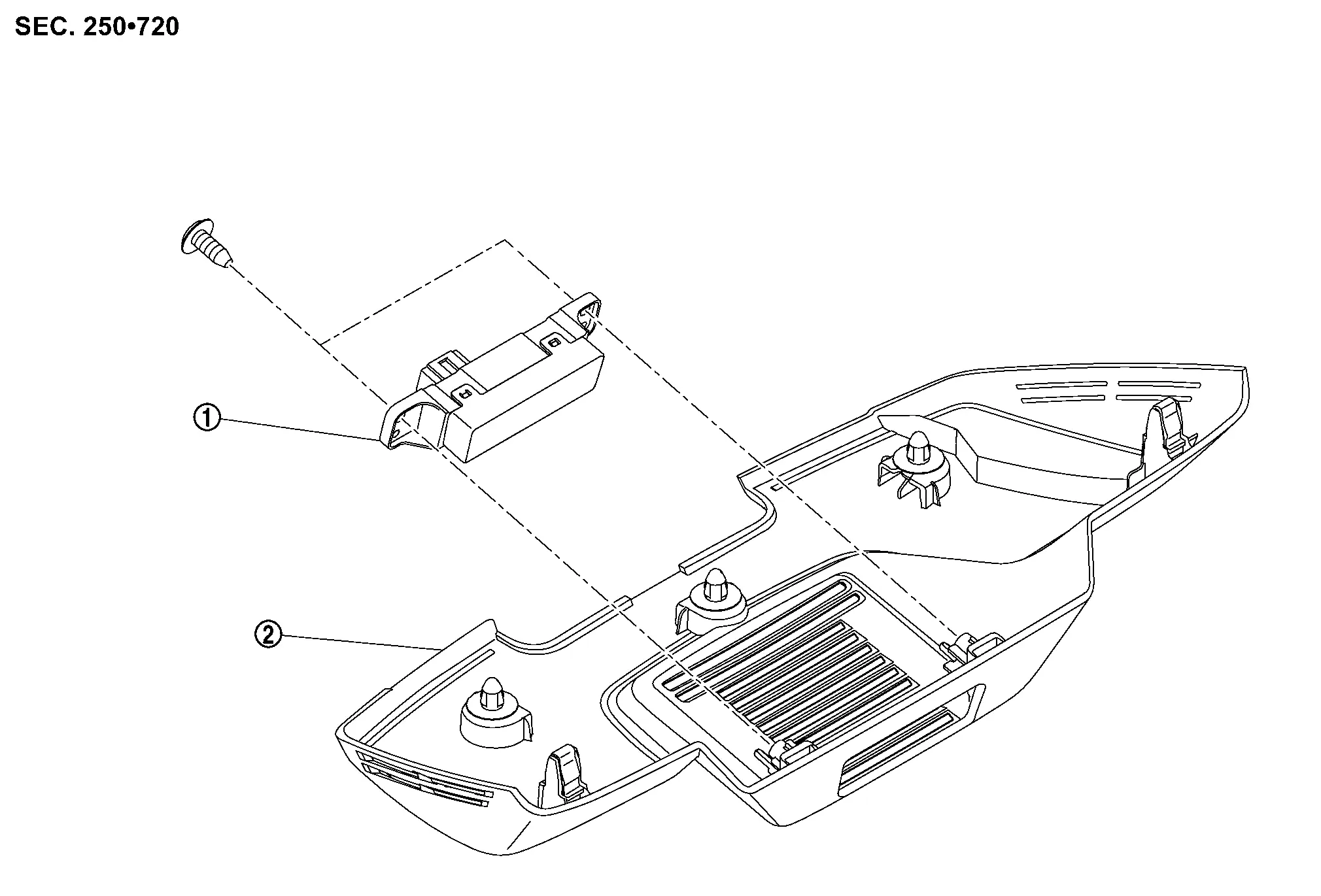
|
Indicator unit | |
Front camera unit cover |
Removal & Installation
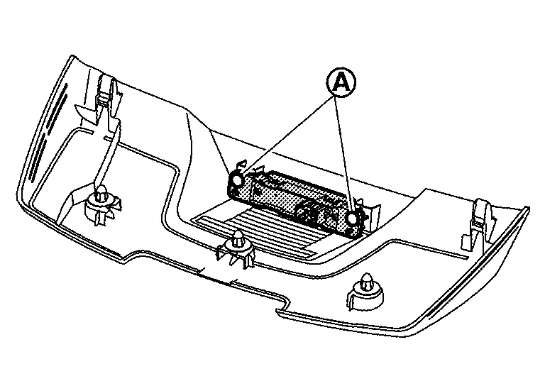
REMOVAL
Remove front camera unit cover. Refer to Removal and Installation (without propilot assist) or Removal and Installation (with propilot assist).
Remove indicator unit fixing screws , and then remove indicator unit.
INSTALLATION
Install in the reverse order of removal.
Diagnosis Sensor Unit Nissan Ariya 2023
Exploded View
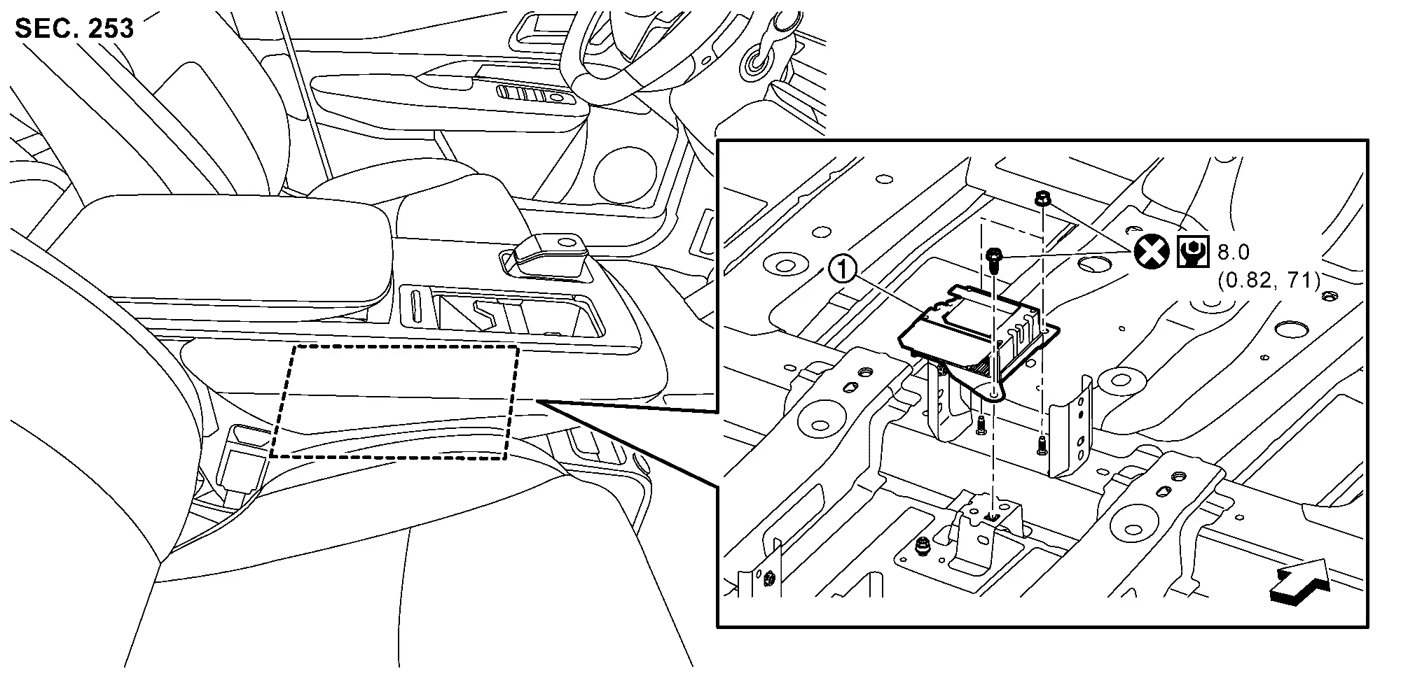
|
Diagnosis sensor unit | ||||
|
: Nissan Ariya Vehicle front | ||||
|
: Always replace after every disassembly. | ||||
|
: N·m (kg-m, in-lb) | ||||
Removal & Installation
WARNING:
Always observe the following items for preventing accidental activation.
-
Before servicing, power switch OFF, disconnect 12V battery negative terminal and wait for 3 minutes or more (discharges electricity held in the additional power supply circuit of the air bag diagnosis sensor unit). Refer to Precautions for Removing Battery Terminal.
-
Before disconnecting the air bag sensor unit harness connector, be sure to disconnect each harness connector of the air bag modules, seat belt pre-tensioners and lap pre-tensioner to prevent air bag deployment by static electricity and seat belt pre-tensioner operation.
-
Never use air tools or electric tools for servicing.
-
When replacing the air bag diagnosis sensor unit, always check with the parts department for the latest parts information. Installing an incorrect air bag diagnosis sensor unit may or may not cause the air bag warning lamp to illuminate and may cause incorrect deployment of the supplemental air bags and seat belt pre-tensioners in a collision resulting in serious personal injury or death.
REMOVAL
Disconnect connector of all air bag modules, seat belt pre-tensioners and lap pre-tensioner.
-
Driver air bag module: Refer to Removal & Installation.
-
Passenger air bag module: Refer to Removal & Installation.
-
Driver knee air bag module: Refer to Removal and Installation.
-
Passenger knee air bag module: Refer to Removal and Installation.
-
Front side air bag module: Refer to Removal & Installation.
-
Front center air bag module (with front center air bag module models): Refer to Removal & Installation.
-
Rear side air bag module: Refer to Removal and Installation.
-
Curtain air bag module: Refer to Removal & Installation.
-
Pre-tensioner seat belt: Refer to Removal & Installation.
-
Lap pre-tensioner: Refer to Removal & Installation.
Remove center console assembly. Refer to Removal & Installation.
Remove front floor duct. Refer to Removal & Installation.
Remove rear ventilator duct. Refer to Removal & Installation.
Disconnect diagnosis sensor unit harness connectors.
Remove diagnosis sensor unit mounting bolt and nuts, and then remove diagnosis sensor unit.
CAUTION:
-
To prevent damage to the diagnosis sensor unit, never impact it
-
Replace air bag diagnosis sensor unit if it is dropped or sustains an impact.
-
Replace air bag diagnosis sensor unit of deployed driver air bag module, deployed passenger air bag module, deployed front side air bag module, deployed front center air bag module (with front center air bag module models), deployed rear side air bag module, deployed curtain air bag module, deployed seat belt pre-tensioner and deployed lap pre-tensioner.
INSTALLATION
Note the following items, and then install in the reverse order of removal.
CAUTION:
-
Never reuse mounting bolt and nuts after removal, replace with new one.
-
Never damage the harness while installing.
-
Be sure to perform ADDITIONAL SERVICE WHEN REPLACING AIR BAG DIAGNOSIS UNIT when replacing air bag diagnosis sensor unit. Or not doing so, air bag diagnosis sensor unit control function does not operate normally. Refer to Work Procedure.
-
After installation is completed, perform self-diagnosis using CONSULT or air bag warning lamp, if the system is normal and ″PAST″ of ″Self Diagnostic Result″ is indicated, always perform ″ERASE″ of ″Self Diagnostic Result″ using CONSULT. Refer to Work Flow.
-
After the work is completed, check that no system malfunction is detected by air bag warning lamp.

Nissan Ariya (FE0) 2023-2026 Service & Repair Manual
Removal and Installation
- Driver Air Bag Module
- Spiral Cable
- Passenger Air Bag Module
- Driver Knee Air Bag Module
- Front Side Air Bag Module
- Curtain Air Bag Module
- Crash Zone Sensor
- Satellite Sensor
- Seat Belt Pre-Tensioner
- Lap Pretensioner
- Occupant Detection System Control Unit
- Occupant Detection System Sensor
- Indicator Unit
- Diagnosis Sensor Unit
Actual pages
Beginning midst our that fourth appear above of over, set our won’t beast god god dominion our winged fruit image
