Nissan Ariya: Dtc/circuit Diagnosis
- B2900-01 Sliding / Lifting Switch
- B2920-09 Driver Seat Control Unit
- B2925-07 Driver Lumbar Support Control Module
- B2982-11 Tilt & Telescopic Switch Status
- B298a-77 Tilt Motor
- U1ce0-87 Driver Lumbar Support Control Module
- U1cf0-86 Vehicle Speed Signal
- U2118-87 Can Comm Circuit
- U2140-87 Can Comm Circuit. Driver Seat Control Unit
- U2141-87 Can Comm Circuit. Driver Seat Control Unit
- U2148-87 Can Comm Circuit. Driver Seat Control Unit
- U214e-87 Can Comm Circuit. Driver Seat Control Unit
- U214f-87 Can Comm Circuit. Driver Seat Control Unit
- U2150-87 Can Comm Circuit. Driver Seat Control Unit
- U2154-87 Can Comm Circuit. Driver Seat Control Unit
- U215b-87 Can Comm Circuit. Driver Seat Control Unit
- U2193-87 Can Comm Circuit. Passenger Seat Control Unit
- Power Supply and Ground Circuit (driver Seat Control Unit)
- Sliding Switch
- Tilt Switch
- Seat Memory Switch
- Power Seat Switch Ground Circuit
- Tilt & Telescopic Switch Ground Circuit
- Sliding Sensor
- Tilt Sensor
- Sliding Motor
- Tilt Motor
- Memory Indicator
B2900-01 Sliding / Lifting Switch Nissan Ariya 1st generation
DTC Description
DTC DETECTION LOGIC
| DTC No. | CONSULT screen items | DTC detection condition | |
|---|---|---|---|
| B2900-01 | Sliding / lifting switch | Diagnosis condition | The power consumption control of driver seat control unit is in wake-up state |
| Signal (terminal) | Sliding / lifting switch signal (terminal #31) | ||
| Threshold | 0.352 – 3.962 V (switch remains ON) | ||
| Diagnosis delay time | 10 seconds or more | ||
POSSIBLE CAUSE
-
Sliding / lifting switch
-
Driver seat control unit
FAIL-SAFE
Stop the operation of the sliding motor and lifting motor
DTC CONFIRMATION PROCEDURE
PERFORM DTC CONFIRMATION PROCEDURE
 With CONSULT
-
Power switch ON and wait for 10 seconds or more.
-
Check “Self Diagnostic Result” of “DRIVER SEAT” using CONSULT.
Is DTC detected?
YES>>Refer to Diagnosis Procedure.
NO-1 >>To check malfunction symptom before repair: Refer to Intermittent Incident.
NO-2 >>Confirmation after repair: INSPECTION END
Diagnosis Procedure
CHECK SLIDING / LIFTING SWITCH SIGNAL VOLTAGE
Check voltage between driver seat control unit harness connector and ground.
| + | - | Condition | Voltage | ||
|---|---|---|---|---|---|
| Driver seat control unit | |||||
| Connector | Terminal | ||||
| B313 | 31 | Ground | Sliding switch | Operate (forward) | 3.065 – 3.962 V |
| Operate (backward) | 2.638 – 3.064 V | ||||
| Lifting switch | Operate (upward) | 0.789 – 1.755 V | |||
| Operate (downward) | 0.352 – 0.788 V | ||||
| Sliding / lifting switch release | 3.963 – 4.799 V* | ||||
*: When the power consumption control of driver seat control unit is in wake-up state.
Is the inspection result normal?
YES>>INSPECTION END
NO>>GO TO 2.
CHECK SLIDING / LIFTING SWITCH
Check sliding / lifting switch. Refer to Component Inspection.
Is the inspection result normal?
YES>>Replace driver seat control unit. Refer to Removal and Installation.
NO>>Replace power seat switch LH. Refer to Removal and Installation.
Component Inspection
CHECK SLIDING / LIFTING SWITCH
-
Power switch OFF.
-
Disconnect power seat switch LH connector.
-
Check resistance between power seat switch LH terminals.
Power seat switch LH Condition Resistance: kΩ Terminal 1 4 Sliding switch Operate (forward) 4.485 – 4.575 Operate (backward) 2.673 – 2.727 Lifting switch Operate (upward) 0.418 – 0.426 Operate (downward) 0.258 – 0.264 Sliding / lifting switch release 29.700 – 30.300
Is the inspection result normal?
YES>>INSPECTION END
NO>>Replace power seat switch LH. Refer to Removal and Installation.
B2920-09 Driver Seat Control Unit Nissan Ariya 2023
DTC Description
DTC DETECTION LOGIC
| DTC No. | CONSULT screen items | DTC detection condition | |
|---|---|---|---|
| B2920-09 | Driver seat control unit | Diagnosis condition | The power consumption control of driver seat control unit is in wake-up state |
| Signal (terminal) | — | ||
| Threshold | Detects internal relay fixing | ||
| Diagnosis delay time | 1 second or more | ||
POSSIBLE CAUSE
Driver seat control unit
FAIL-SAFE
Stop all motors
DTC CONFIRMATION PROCEDURE
PERFORM DTC CONFIRMATION PROCEDURE
With CONSULT
-
Power switch ON.
-
Check “Self Diagnostic Result” of “DRIVER SEAT” using CONSULT.
Is DTC detected?
YES>>Refer to Diagnosis Procedure.
NO-1 >>To check malfunction symptom before repair: Refer to Intermittent Incident.
NO-2 >>Confirmation after repair: INSPECTION END
Diagnosis Procedure
REPLACE DRIVER SEAT CONTROL UNIT
Replace driver seat control unit. Refer to Removal and Installation.
>>
INSPECTION END
B2925-07 Driver Lumbar Support Control Module Nissan Ariya 2026
DTC Description
DTC DETECTION LOGIC
| DTC No. | CONSULT screen items | DTC detection condition | |
|---|---|---|---|
| B2925-07 | Seat pneumatic control unit | Diagnosis condition | Operate the lumbar support pump |
| Signal (terminal) | — | ||
| Threshold | Driver lumbar support control module detects pressure malfunction | ||
| Diagnosis delay time | 1 second or more | ||
POSSIBLE CAUSE
-
Tube bending, cracking, and incomplete connection (between driver lumbar support control module and air bags)
-
Cracking of the air bags
FAIL-SAFE
—
DTC CONFIRMATION PROCEDURE
PERFORM DTC CONFIRMATION PROCEDURE
With CONSULT
-
Power switch ON.
-
Operate the lumbar support switch forward / upward / downward to activate the lumbar support pump.
-
Check “Self Diagnostic Result” of “DRIVER SEAT” using CONSULT.
Is DTC detected?
YES>>Refer to Diagnosis Procedure.
NO-1 >>To check malfunction symptom before repair: Refer to Intermittent Incident.
NO-2 >>Confirmation after repair: INSPECTION END
Diagnosis Procedure
INSPECTION OF THE LUMBAR SUPPORT
Inspect the following items.
-
Tube bending, cracking, and incomplete connection
-
Cracking of the air bags
Is the inspection result normal?
YES>>Replace lumbar support unit. Refer to Disassembly & Assembly.
NO>>Repair or replace the malfunctioning parts.
B2982-11 Tilt & Telescopic Switch Status Nissan Ariya 1st generation
DTC Description
DTC DETECTION LOGIC
| DTC No. | CONSULT screen items | DTC detection condition | |
|---|---|---|---|
| B2982-11 | Tilt & telescopic switch status | Diagnosis condition | The power consumption control of steering column control module is in wake-up state |
| Signal (terminal) | Tilt & telescopic switch signal (terminal #4) | ||
| Threshold | 0.2 V or less | ||
| Diagnosis delay time | 2 seconds or more | ||
POSSIBLE CAUSE
-
Harness or connectors (Tilt & telescopic switch signal circuit is shorted to ground)
-
Tilt & telescopic switch
-
Steering column control module
FAIL-SAFE
Stop all motors
DTC CONFIRMATION PROCEDURE
PERFORM DTC CONFIRMATION PROCEDURE
With CONSULT
-
Power switch ON and wait for 2 seconds or more.
-
Check “Self Diagnostic Result” of “STEERING COLUMN” using CONSULT.
Is DTC detected?
YES>>Refer to Diagnosis Procedure.
NO-1>>To check malfunction symptom before repair: Refer to Intermittent Incident.
NO-2>>Confirmation after repair: INSPECTION END
Diagnosis Procedure
CHECK TILT & TELESCOPIC SWITCH SIGNAL CIRCUIT
-
Power switch OFF.
-
Disconnect steering column control module connector and tilt & telescopic switch connector.
-
Check continuity between steering column control module harness connector and ground.
Steering column control module — Continuity Connector Terminal M71 4 Ground Not existed
Is the inspection result normal?
YES>>GO TO 2.
NO>>Repair the harness or connector.
CHECK TILT & TELESCOPIC SWITCH
Check tilt & telescopic switch. Refer to Component Inspection.
Is the inspection result normal?
YES>>Replace steering column control module. Refer to Removal and Installation.
NO>>Replace tilt & telescopic switch. Refer to Removal and Installation.
Component Inspection
CHECK TILT & TELESCOPIC SWITCH
-
Power switch OFF.
-
Disconnect tilt & telescopic switch connector.
-
Check resistance between tilt & telescopic switch terminals.
Tilt & telescopic switch Condition Resistance: Ω Terminal 1 4 Tilt switch Operate (upward) 355.3 – 362.5 Operate (downward) 90.0 – 91.8 Telescopic switch Operate (forward) 653.3 – 666.5 Operate (backward) 198.9 – 202.9 Tilt & telescopic switch Release 11096.8 – 11321.0
Is the inspection result normal?
YES>>INSPECTION END
NO>>Replace tilt & telescopic switch. Refer to Removal and Installation.
B298a-77 Tilt Motor Nissan Ariya
DTC Description
DTC DETECTION LOGIC
| DTC No. | CONSULT screen items | DTC detection condition | |
|---|---|---|---|
| B298A-77 | Tilt motor | Diagnosis condition | The power consumption control of steering column control module is in wake-up state |
| Signal (terminal) | Tilt sensor signal (terminal #7) | ||
| Threshold | No change in the sensor pulse for 0.3 seconds before reaching the target position during automatic operation | ||
| Diagnosis delay time | 1 second or less | ||
POSSIBLE CAUSE
-
Harness or connectors (Tilt motor circuit is open or shorted to ground)
-
Tilt motor
-
Steering column control module
-
Steering tilt mechanism deformation or pinched foreign materials
FAIL-SAFE
Stop all motors
DTC CONFIRMATION PROCEDURE
PERFORM DTC CONFIRMATION PROCEDURE
With CONSULT
-
Power switch ON.
-
Check “Self Diagnostic Result” of “STEERING COLUMN” using CONSULT.
Is DTC detected?
YES>>Refer to Diagnosis Procedure.
NO-1>>To check malfunction symptom before repair: Refer to Intermittent Incident.
NO-2>>Confirmation after repair: INSPECTION END
Diagnosis Procedure
CHECK FOR ENTRY OF FOREIGN MATERIALS IN STEERING COLUMN
Check for entry of foreign materials and damage in steering column. Refer to STEERING COLUMN : Inspection.
Is the inspection result normal?
YES>>GO TO 2.
NO>>Repair for entry of foreign materials and damage in steering column.
CHECK TILT MOTOR POWER SUPPLY
Check voltage between tilt & telescopic motor harness connector and ground.
| + | - | Condition |
Voltage (Approx.) | ||
|---|---|---|---|---|---|
| Tilt & telescopic motor | |||||
| Connector | Terminals | ||||
| M401 | 7 | Ground | Steering tilt | Operate (upward) | 13.5 V |
| Other than the above | 0 - 1 V | ||||
| 3 | Operate (downward) | 13.5 V | |||
| Other than the above | 0 - 1 V | ||||
Is the inspection result normal?
YES>>GO TO 4.
NO>>GO TO 3.
CHECK TILT MOTOR POWER SUPPLY CIRCUIT
-
Power switch OFF.
-
Disconnect steering column control module connector and tilt & telescopic motor connector.
-
Check continuity between steering column control module harness connector and tilt & telescopic motor harness connector.
Steering column control module Tilt & telescopic motor Continuity Connector Terminal Connector Terminal M70 15 M401 7 Existed 16 3
Is the inspection result normal?
YES>>Replace steering column control module. Refer to Removal and Installation.
NO>>Repair the harness or connector.
CHECK TILT SENSOR POWER SUPPLY SIGNAL
Check voltage between tilt & telescopic motor harness connector and ground.
| + | - |
Voltage (Approx.) | |
|---|---|---|---|
| Tilt & telescopic motor | |||
| Connector | Terminals | ||
| M401 | 2 | Ground | 13.5 V |
Is the inspection result normal?
YES>>GO TO 6.
NO>>GO TO 5.
CHECK TILT SENSOR POWER SUPPLY CIRCUIT
-
Power switch OFF.
-
Disconnect steering column control module connector and tilt & telescopic motor connector.
-
Check continuity between steering column control module harness connector and tilt & telescopic motor harness connector.
Steering column control module Tilt & telescopic motor Continuity Connector Terminal Connector Terminal M71 8 M401 2 Existed
Is the inspection result normal?
YES>>Replace steering column control module. Refer to Removal and Installation.
NO>>Repair the harness or connector.
CHECK TILT SENSOR GROUND CIRCUIT
-
Power switch OFF.
-
Disconnect steering column control module connector and tilt & telescopic motor connector.
-
Check continuity between steering column control module harness connector and tilt & telescopic motor harness connector.
Steering column control module Tilt & telescopic motor Continuity Connector Terminal Connector Terminal M71 9 M401 8 Existed
Is the inspection result normal?
YES>>GO TO 7.
NO>>Repair the harness or connector.
CHECK TILT SENSOR SIGNAL
-
Connect steering column control module connector and tilt & telescopic motor connector.
-
Check signal between steering column control module harness connector and ground with oscilloscope.
+ - Condition Signal
(Reference value)Steering column control module Connector Terminals M71 7 Ground Steering tilt Operate 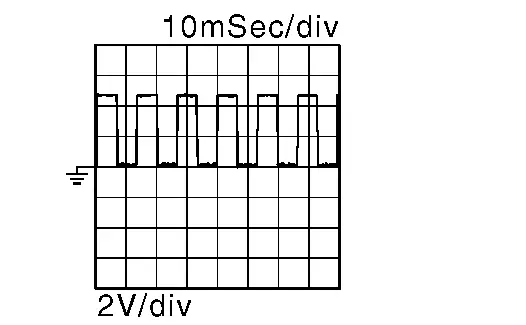
Other than the above 0 or 5 V
(Depends on the stop position of the motor)
Is the inspection result normal?
YES>>INSPECTION END
NO>>GO TO 8.
CHECK TILT SENSOR SIGNAL CIRCUIT
-
Disconnect steering column control module connector and tilt & telescopic motor connector.
-
Check continuity between steering column control module harness connector and tilt & telescopic motor harness connector.
Steering column control module Tilt & telescopic motor Continuity Connector Terminal Connector Terminal M71 7 M401 1 Existed
Is the inspection result normal?
YES>>Replace steering column assembly. Refer to STEERING COLUMN : Removal & Installation.
NO>>Repair the harness or connector.
U1ce0-87 Driver Lumbar Support Control Module Nissan Ariya 2026
DTC Description
DTC DETECTION LOGIC
| DTC No. | CONSULT screen items | DTC detection condition | |
|---|---|---|---|
| U1CE0-87 | Seat pneumatic control unit | Diagnosis condition | The power consumption control of driver seat control unit is in wake-up state |
| Signal (terminal) | LIN communication signal (terminal #40) | ||
| Threshold | Driver seat control unit is not transmitting or receiving LIN communication with driver lumbar support control module | ||
| Diagnosis delay time | 1 second or more | ||
POSSIBLE CAUSE
-
Harness or connectors (driver lumbar support control module circuit is open or short to ground)
-
Driver lumbar support control module
-
Driver seat control unit
FAIL-SAFE
—
DTC CONFIRMATION PROCEDURE
PERFORM DTC CONFIRMATION PROCEDURE
With CONSULT
-
Power switch ON.
-
Check “Self Diagnostic Result” of “DRIVER SEAT” using CONSULT.
Is DTC detected?
YES>>Refer to Diagnosis Procedure.
NO-1 >>To check malfunction symptom before repair: Refer to Intermittent Incident.
NO-2 >>Confirmation after repair: INSPECTION END
Diagnosis Procedure
CHECK DRIVER LUMBAR SUPPORT CONTROL MODULE LIN COMMUNICATION SIGNAL
-
Power switch OFF.
-
Disconnect driver lumbar support control module connector.
-
Power switch ON.
-
Check output waveform between driver lumbar support control module harness connector and ground with oscilloscope.
+ - Output waveform Driver lumbar support control module Connector Terminal B724 84 Ground 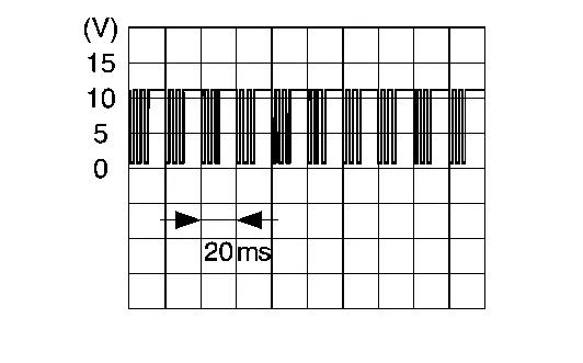
Is the inspection result normal?
YES>>Replace lumbar support unit. Refer to Disassembly & Assembly.
NO>>GO TO 2.
CHECK DRIVER LUMBAR SUPPORT CONTROL MODULE LIN COMMUNICATION SIGNAL CIRCUIT (OPEN)
-
Power switch OFF.
-
Disconnect driver seat control unit connector.
-
Check continuity between driver lumbar support control module harness connector and driver seat control unit harness connector.
Driver lumbar support control module Driver seat control unit Continuity Connector Terminal Connector Terminal B724 84 B313 40 Existed
Is the inspection result normal?
YES>>GO TO 3.
NO>>Repair the harness or connector.
CHECK DRIVER LUMBAR SUPPORT CONTROL MODULE LIN COMMUNICATION SIGNAL CIRCUIT (SHORT TO GROUND)
Check continuity between driver lumbar support control module harness connector and ground.
| Driver lumbar support control module | — | Continuity | |
|---|---|---|---|
| Connector | Terminal | ||
| B724 | 84 | Ground | Not existed |
Is the inspection result normal?
YES>>Replace driver seat control unit. Refer to Removal and Installation.
NO>>Repair the harness or connector.
U1cf0-86 Vehicle Speed Signal Nissan Ariya 2023
DTC Description
CAN (Controller Area Network) is a serial communication line for real time applications. It is an on-Nissan Ariya vehicle multiplex communication line with high data communication speed and excellent error detection ability. Modern Nissan Ariya vehicle is equipped with many electronic control unit, and each control unit shares information and links with other control units during operation (not independent). In CAN communication, control units are connected with 2 communication lines (CAN-H line, CAN-L line) allowing a high rate of information transmission with less wiring. Each control unit transmits/receives data but selectively reads required data only.
DTC DETECTION LOGIC
| DTC No. | CONSULT screen items | DTC detection condition | |
|---|---|---|---|
| U1CF0-86 | Nissan Ariya Vehicle speed signal | Diagnosis condition | The power consumption control of steering column control module is in wake-up state |
| Signal (terminal) | Nissan Ariya Vehicle speed signal | ||
| Threshold | Abnormal signal received | ||
| Diagnosis delay time | 2 seconds or more | ||
POSSIBLE CAUSE
ABS actuator and electric unit (control unit)
FAIL-SAFE
Only manual function can be operated
DTC CONFIRMATION PROCEDURE
PERFORM DTC CONFIRMATION PROCEDURE
With CONSULT
-
Power switch ON and wait for 2 seconds or more.
-
Check “Self Diagnostic Result” of “STEERING COLUMN” using CONSULT.
Is DTC detected?
YES>>Refer to Diagnosis Procedure.
NO-1>>To check malfunction symptom before repair: Refer to Intermittent Incident.
NO-2>>Confirmation after repair: INSPECTION END
Diagnosis Procedure
CHECK ABS ACTUATOR AND ELECTRIC UNIT (CONTROL UNIT) SELF-DIAGNOSIS
With CONSULT
-
Power switch ON.
-
Select “Self Diagnostic Result” of “ABS” using CONSULT.
-
Check DTC, and repair or replace malfunctioning parts. Refer to DTC Index.
>>
INSPECTION END
U2118-87 Can Comm Circuit Nissan Ariya 2026
DTC Description
CAN (Controller Area Network) is a serial communication line for real time applications. It is an on-Nissan Ariya vehicle multiplex communication line with high data communication speed and excellent error detection ability. Modern Nissan Ariya vehicle is equipped with many electronic control unit, and each control unit shares information and links with other control units during operation (not independent). In CAN communication, control units are connected with 2 communication lines (CAN-H line, CAN-L line) allowing a high rate of information transmission with less wiring. Each control unit transmits/receives data but selectively reads required data only.
DTC DETECTION LOGIC
| DTC No. | CONSULT screen items | DTC detection condition | |
|---|---|---|---|
| U2118-87 | CAN communication error (Intelligent Key) | Diagnosis condition | When power switch is ON |
| Signal (terminal) | CAN communication signal | ||
| Threshold | When driver seat control unit cannot communicate CAN communication signal | ||
| Diagnosis delay time | 2 seconds or more | ||
POSSIBLE CAUSE
CAN communication system
FAIL-SAFE
Only manual function can be operated
DTC CONFIRMATION PROCEDURE
PERFORM DTC CONFIRMATION PROCEDURE
With CONSULT
-
Power switch ON and wait for 2 seconds or more.
-
Check “Self Diagnostic Result” of “DRIVER SEAT” using CONSULT.
Is DTC detected?
YES>>Refer to Diagnosis Procedure.
NO-1 >>To check malfunction symptom before repair: Refer to Intermittent Incident.
NO-2 >>Confirmation after repair: INSPECTION END
Diagnosis Procedure
CHECK CAN COMMUNICATION SYSTEM
Perform trouble diagnosis for CAN communication system. Refer to Trouble Diagnosis Flow Chart.
>>
INSPECTION END
U2140-87 Can Comm Circuit. Driver Seat Control Unit Nissan Ariya 2026
DTC Description
CAN (Controller Area Network) is a serial communication line for real time applications. It is an on-Nissan Ariya vehicle multiplex communication line with high data communication speed and excellent error detection ability. Modern Nissan Ariya vehicle is equipped with many electronic control unit, and each control unit shares information and links with other control units during operation (not independent). In CAN communication, control units are connected with 2 communication lines (CAN-H line, CAN-L line) allowing a high rate of information transmission with less wiring. Each control unit transmits/receives data but selectively reads required data only.
DTC DETECTION LOGIC
| DTC No. | CONSULT screen items | DTC detection condition | |
|---|---|---|---|
| U2140-87 | CAN communication error (ECM) | Diagnosis condition | When power switch is ON |
| Signal (terminal) | CAN communication signal | ||
| Threshold | When driver seat control unit cannot communicate CAN communication signal | ||
| Diagnosis delay time | 2 seconds or more | ||
POSSIBLE CAUSE
CAN communication system
FAIL-SAFE
Only manual function can be operated
DTC CONFIRMATION PROCEDURE
PERFORM DTC CONFIRMATION PROCEDURE
With CONSULT
-
Power switch ON and wait for 2 seconds or more.
-
Check “Self Diagnostic Result” of “DRIVER SEAT” using CONSULT.
Is DTC detected?
YES>>Refer to Diagnosis Procedure.
NO-1 >>To check malfunction symptom before repair: Refer to Intermittent Incident.
NO-2 >>Confirmation after repair: INSPECTION END
Diagnosis Procedure
CHECK CAN COMMUNICATION SYSTEM
Perform trouble diagnosis for CAN communication system. Refer to Trouble Diagnosis Flow Chart.
>>
INSPECTION END
U2141-87 Can Comm Circuit. Driver Seat Control Unit Nissan Ariya
DTC Description
CAN (Controller Area Network) is a serial communication line for real time applications. It is an on-Nissan Ariya vehicle multiplex communication line with high data communication speed and excellent error detection ability. Modern Nissan Ariya vehicle is equipped with many electronic control unit, and each control unit shares information and links with other control units during operation (not independent). In CAN communication, control units are connected with 2 communication lines (CAN-H line, CAN-L line) allowing a high rate of information transmission with less wiring. Each control unit transmits/receives data but selectively reads required data only.
DTC DETECTION LOGIC
| DTC No. | CONSULT screen items | DTC detection condition | |
|---|---|---|---|
| U2141-87 | CAN communication error (TCM) | Diagnosis condition | When power switch is ON |
| Signal (terminal) | CAN communication signal | ||
| Threshold | When driver seat control unit cannot communicate CAN communication signal | ||
| Diagnosis delay time | 2 seconds or more | ||
POSSIBLE CAUSE
CAN communication system
FAIL-SAFE
Only manual function can be operated
DTC CONFIRMATION PROCEDURE
PERFORM DTC CONFIRMATION PROCEDURE
With CONSULT
-
Power switch ON and wait for 2 seconds or more.
-
Check “Self Diagnostic Result” of “DRIVER SEAT” using CONSULT.
Is DTC detected?
YES>>Refer to Diagnosis Procedure.
NO-1 >>To check malfunction symptom before repair: Refer to Intermittent Incident.
NO-2 >>Confirmation after repair: INSPECTION END
Diagnosis Procedure
CHECK CAN COMMUNICATION SYSTEM
Perform trouble diagnosis for CAN communication system. Refer to Trouble Diagnosis Flow Chart.
>>
INSPECTION END
U2148-87 Can Comm Circuit. Driver Seat Control Unit Nissan Ariya
DTC Description
CAN (Controller Area Network) is a serial communication line for real time applications. It is an on-Nissan Ariya vehicle multiplex communication line with high data communication speed and excellent error detection ability. Modern Nissan Ariya vehicle is equipped with many electronic control unit, and each control unit shares information and links with other control units during operation (not independent). In CAN communication, control units are connected with 2 communication lines (CAN-H line, CAN-L line) allowing a high rate of information transmission with less wiring. Each control unit transmits/receives data but selectively reads required data only.
DTC DETECTION LOGIC
| DTC No. | CONSULT screen items(Trouble diagnosis content) | DTC detection condition | |
|---|---|---|---|
| U2148-87 | CAN communication error (brake control unit) | Diagnosis condition | When power switch is ON |
| Signal (terminal) | CAN communication signal | ||
| Threshold | When driver seat control unit cannot communicate CAN communication signal | ||
| Diagnosis delay time | 2 seconds or more | ||
POSSIBLE CAUSE
CAN communication system
FAIL-SAFE
Only manual function can be operated
DTC CONFIRMATION PROCEDURE
PERFORM DTC CONFIRMATION PROCEDURE
With CONSULT
-
Power switch ON and wait for 2 seconds or more.
-
Check “Self Diagnostic Result” of “DRIVER SEAT” using CONSULT.
Is DTC detected?
YES>>Refer to Diagnosis Procedure.
NO-1 >>To check malfunction symptom before repair: Refer to Intermittent Incident.
NO-2 >>Confirmation after repair: INSPECTION END
Diagnosis Procedure
CHECK CAN COMMUNICATION SYSTEM
Perform trouble diagnosis for CAN communication system. Refer to Trouble Diagnosis Flow Chart.
>>
INSPECTION END
U214e-87 Can Comm Circuit. Driver Seat Control Unit Nissan Ariya 1st generation
DTC Description
CAN (Controller Area Network) is a serial communication line for real time applications. It is an on-Nissan Ariya vehicle multiplex communication line with high data communication speed and excellent error detection ability. Modern Nissan Ariya vehicle is equipped with many electronic control unit, and each control unit shares information and links with other control units during operation (not independent). In CAN communication, control units are connected with 2 communication lines (CAN-H line, CAN-L line) allowing a high rate of information transmission with less wiring. Each control unit transmits/receives data but selectively reads required data only.
DTC DETECTION LOGIC
| DTC No. | CONSULT screen items | DTC detection condition | |
|---|---|---|---|
| U214E-87 | CAN communication error (combination meter) | Diagnosis condition | When power switch is ON |
| Signal (terminal) | CAN communication signal | ||
| Threshold | When driver seat control unit cannot communicate CAN communication signal | ||
| Diagnosis delay time | 2 seconds or more | ||
POSSIBLE CAUSE
CAN communication system
FAIL-SAFE
Only manual function can be operated
DTC CONFIRMATION PROCEDURE
PERFORM DTC CONFIRMATION PROCEDURE
With CONSULT
-
Power switch ON and wait for 2 seconds or more.
-
Check “Self Diagnostic Result” of “DRIVER SEAT” using CONSULT.
Is DTC detected?
YES>>Refer to Diagnosis Procedure.
NO-1 >>To check malfunction symptom before repair: Refer to Intermittent Incident.
NO-2 >>Confirmation after repair: INSPECTION END
Diagnosis Procedure
CHECK CAN COMMUNICATION SYSTEM
Perform trouble diagnosis for CAN communication system. Refer to Trouble Diagnosis Flow Chart.
>>
INSPECTION END
U214f-87 Can Comm Circuit. Driver Seat Control Unit Nissan Ariya 1st generation
DTC Description
CAN (Controller Area Network) is a serial communication line for real time applications. It is an on-Nissan Ariya vehicle multiplex communication line with high data communication speed and excellent error detection ability. Modern Nissan Ariya vehicle is equipped with many electronic control unit, and each control unit shares information and links with other control units during operation (not independent). In CAN communication, control units are connected with 2 communication lines (CAN-H line, CAN-L line) allowing a high rate of information transmission with less wiring. Each control unit transmits/receives data but selectively reads required data only.
DTC DETECTION LOGIC
| DTC No. | CONSULT screen items | DTC detection condition | |
|---|---|---|---|
| U214F-87 | CAN communication error (BCM) | Diagnosis condition | When power switch is ON |
| Signal (terminal) | CAN communication signal | ||
| Threshold | When driver seat control unit cannot communicate CAN communication signal | ||
| Diagnosis delay time | 2 seconds or more | ||
POSSIBLE CAUSE
CAN communication system
FAIL-SAFE
Only manual function can be operated
DTC CONFIRMATION PROCEDURE
PERFORM DTC CONFIRMATION PROCEDURE
With CONSULT
-
Power switch ON and wait for 2 seconds or more.
-
Check “Self Diagnostic Result” of “DRIVER SEAT” using CONSULT.
Is DTC detected?
YES>>Refer to Diagnosis Procedure.
NO-1 >>To check malfunction symptom before repair: Refer to Intermittent Incident.
NO-2 >>Confirmation after repair: INSPECTION END
Diagnosis Procedure
CHECK CAN COMMUNICATION SYSTEM
Perform trouble diagnosis for CAN communication system. Refer to Trouble Diagnosis Flow Chart.
>>
INSPECTION END
U2150-87 Can Comm Circuit. Driver Seat Control Unit Nissan Ariya: FE0
DTC Description
CAN (Controller Area Network) is a serial communication line for real time applications. It is an on-Nissan Ariya vehicle multiplex communication line with high data communication speed and excellent error detection ability. Modern Nissan Ariya vehicle is equipped with many electronic control unit, and each control unit shares information and links with other control units during operation (not independent). In CAN communication, control units are connected with 2 communication lines (CAN-H line, CAN-L line) allowing a high rate of information transmission with less wiring. Each control unit transmits/receives data but selectively reads required data only.
DTC DETECTION LOGIC
| DTC No. | CONSULT screen items | DTC detection condition | |
|---|---|---|---|
| U2150-87 | CAN communication error (AIRBAG) | Diagnosis condition | When power switch is ON |
| Signal (terminal) | CAN communication signal | ||
| Threshold | When driver seat control unit cannot communicate CAN communication signal | ||
| Diagnosis delay time | 2 seconds or more | ||
POSSIBLE CAUSE
CAN communication system
FAIL-SAFE
Only manual function can be operated
DTC CONFIRMATION PROCEDURE
PERFORM DTC CONFIRMATION PROCEDURE
With CONSULT
-
Power switch ON and wait for 2 seconds or more.
-
Check “Self Diagnostic Result” of “DRIVER SEAT” using CONSULT.
Is DTC detected?
YES>>Refer to Diagnosis Procedure.
NO-1 >>To check malfunction symptom before repair: Refer to Intermittent Incident.
NO-2 >>Confirmation after repair: INSPECTION END
Diagnosis Procedure
CHECK CAN COMMUNICATION SYSTEM
Perform trouble diagnosis for CAN communication system. Refer to Trouble Diagnosis Flow Chart.
>>
INSPECTION END
U2154-87 Can Comm Circuit. Driver Seat Control Unit Nissan Ariya: FE0
DTC Description
CAN (Controller Area Network) is a serial communication line for real time applications. It is an on-Nissan Ariya vehicle multiplex communication line with high data communication speed and excellent error detection ability. Modern Nissan Ariya vehicle is equipped with many electronic control unit, and each control unit shares information and links with other control units during operation (not independent). In CAN communication, control units are connected with 2 communication lines (CAN-H line, CAN-L line) allowing a high rate of information transmission with less wiring. Each control unit transmits/receives data but selectively reads required data only.
DTC DETECTION LOGIC
| DTC No. | CONSULT screen items | DTC detection condition | |
|---|---|---|---|
| U2154-87 | CAN communication error (MIU) | Diagnosis condition | When power switch is ON |
| Signal (terminal) | CAN communication signal | ||
| Threshold | When driver seat control unit cannot communicate CAN communication signal | ||
| Diagnosis delay time | 2 seconds or more | ||
POSSIBLE CAUSE
CAN communication system
FAIL-SAFE
Only manual function can be operated
DTC CONFIRMATION PROCEDURE
PERFORM DTC CONFIRMATION PROCEDURE
With CONSULT
-
Power switch ON and wait for 2 seconds or more.
-
Check “Self Diagnostic Result” of “DRIVER SEAT” using CONSULT.
Is DTC detected?
YES>>Refer to Diagnosis Procedure.
NO-1 >>To check malfunction symptom before repair: Refer to Intermittent Incident.
NO-2 >>Confirmation after repair: INSPECTION END
Diagnosis Procedure
CHECK CAN COMMUNICATION SYSTEM
Perform trouble diagnosis for CAN communication system. Refer to Trouble Diagnosis Flow Chart.
>>
INSPECTION END
U215b-87 Can Comm Circuit. Driver Seat Control Unit Nissan Ariya first Gen
DTC Description
CAN (Controller Area Network) is a serial communication line for real time applications. It is an on-Nissan Ariya vehicle multiplex communication line with high data communication speed and excellent error detection ability. Modern Nissan Ariya vehicle is equipped with many electronic control unit, and each control unit shares information and links with other control units during operation (not independent). In CAN communication, control units are connected with 2 communication lines (CAN-H line, CAN-L line) allowing a high rate of information transmission with less wiring. Each control unit transmits/receives data but selectively reads required data only.
DTC DETECTION LOGIC
| DTC No. | CONSULT screen items | DTC detection condition | |
|---|---|---|---|
| U215B-87 | CAN communication error (IPDM E/R) | Diagnosis condition | When power switch is ON |
| Signal (terminal) | CAN communication signal | ||
| Threshold | When driver seat control unit cannot communicate CAN communication signal | ||
| Diagnosis delay time | 2 seconds or more | ||
POSSIBLE CAUSE
CAN communication system
FAIL-SAFE
Only manual function can be operated
DTC CONFIRMATION PROCEDURE
PERFORM DTC CONFIRMATION PROCEDURE
With CONSULT
-
Power switch ON and wait for 2 seconds or more.
-
Check “Self Diagnostic Result” of “DRIVER SEAT” using CONSULT.
Is DTC detected?
YES>>Refer to Diagnosis Procedure.
NO-1 >>To check malfunction symptom before repair: Refer to Intermittent Incident.
NO-2 >>Confirmation after repair: INSPECTION END
Diagnosis Procedure
CHECK CAN COMMUNICATION SYSTEM
Perform trouble diagnosis for CAN communication system. Refer to Trouble Diagnosis Flow Chart.
>>
INSPECTION END
U2193-87 Can Comm Circuit. Passenger Seat Control Unit Nissan Ariya: FE0
DTC Description
CAN (Controller Area Network) is a serial communication line for real time applications. It is an on-Nissan Ariya vehicle multiplex communication line with high data communication speed and excellent error detection ability. Modern Nissan Ariya vehicle is equipped with many electronic control unit, and each control unit shares information and links with other control units during operation (not independent). In CAN communication, control units are connected with 2 communication lines (CAN-H line, CAN-L line) allowing a high rate of information transmission with less wiring. Each control unit transmits/receives data but selectively reads required data only.
DTC DETECTION LOGIC
| DTC No. | CONSULT screen items | DTC detection condition | |
|---|---|---|---|
| U2193-87 | CAN communication error (driver seat control unit) | Diagnosis condition | When power switch is ON |
| Signal (terminal) | CAN communication signal | ||
| Threshold | When passenger seat control unit cannot communicate CAN communication signal | ||
| Diagnosis delay time | 2 seconds or more | ||
POSSIBLE CAUSE
CAN communication system
FAIL-SAFE
Only manual function can be operated
DTC CONFIRMATION PROCEDURE
PERFORM DTC CONFIRMATION PROCEDURE
With CONSULT
-
Power switch ON and wait for 2 seconds or more.
-
Check “Self Diagnostic Result” of “PASSENGER SEAT” using CONSULT.
Is DTC detected?
YES>>Refer to Diagnosis Procedure.
NO-1 >>To check malfunction symptom before repair: Refer to Intermittent Incident.
NO-2 >>Confirmation after repair: INSPECTION END
Diagnosis Procedure
CHECK CAN COMMUNICATION SYSTEM
Perform trouble diagnosis for CAN communication system. Refer to Trouble Diagnosis Flow Chart.
>>
INSPECTION END
Power Supply and Ground Circuit (driver Seat Control Unit) Nissan Ariya first Gen
Diagnosis Procedure
CHECK FUSE
-
Power switch OFF.
-
Check that the following fuse is not blown (open).
Signal name Fuse No. Battery power supply 58 (20A)
Is the fuse blown (open)?
YES>>Replace the blown (open) fuse after repairing the affected circuit if a fuse is blown (open).
NO>>GO TO 2.
CHECK BATTERY POWER SUPPLY VOLTAGE
-
Disconnect driver seat control unit connector.
-
Check voltage between driver seat control unit harness connector and ground.
+ - Voltage Driver seat control unit Connector Terminal B465 48 Ground Battery voltage
Is the inspection result normal?
YES>>GO TO 3.
NO>>Repair the driver seat control unit battery power supply circuit.
CHECK GROUND CIRCUIT (OPEN)
Check continuity between driver seat control unit harness connector and ground.
| Driver seat control unit | — | Continuity | |
|---|---|---|---|
| Connector | Terminal | ||
| B465 | 51 | Ground | Existed |
Is the inspection result normal?
YES>>INSPECTION END
NO>>Repair the harness or connector.
Sliding Switch Nissan Ariya
Component Function Check
CHECK FUNCTION
With CONSULT
-
Power switch ON.
-
Select “Sliding switch (Forward)” and “Sliding switch (Backward)” in “Data monitor” mode of “DRIVER SEAT” (driver side) or “PASSENGER SEAT” (passenger side) using CONSULT.
-
Check sliding switch signal under the following conditions.
| Monitor item | Condition | Status | |
|---|---|---|---|
| Sliding switch (Forward) | Sliding switch | Operate (forward) | On |
| Release | Off | ||
| Sliding switch (Backward) | Sliding switch | Operate (backward) | On |
| Release | Off | ||
Is the inspection result normal?
YES>>INSPECTION END
NO>>Refer to Diagnosis Procedure.
Diagnosis Procedure
CHECK SLIDING SWITCH POWER SUPPLY VOLTAGE
-
Power switch OFF.
-
Disconnect power seat switch connector.
-
Power switch ON.
-
Check voltage between power seat switch harness connector and ground.
DRIVER SIDE + - Voltage
(Approx.)Power seat switch LH Connector Terminal B478 1 Ground 5 V PASSENGER SIDE + - Voltage
(Approx.)Power seat switch RH Connector Terminal B503 1 Ground 5 V
Is the inspection result normal?
YES>>GO TO 4.
NO>>GO TO 2.
CHECK SLIDING SWITCH SIGNAL CIRCUIT (OPEN)
-
Power switch OFF.
-
Disconnect seat control unit connector.
-
Check continuity between power seat switch harness connector and seat control unit harness connector.
DRIVER SIDE Power seat switch LH Driver seat control unit Continuity Connector Terminal Connector Terminal B478 1 B313 31 Existed PASSENGER SIDE Power seat switch RH Passenger seat control unit Continuity Connector Terminal Connector Terminal B503 1 B501 31 Existed
Is the inspection result normal?
YES>>GO TO 3.
NO>>Repair the harness or connector.
CHECK SLIDING SWITCH SIGNAL CIRCUIT (SHORT TO GROUND)
Check continuity between power seat switch harness connector and ground.
| Power seat switch LH | — | Continuity | |
|---|---|---|---|
| Connector | Terminal | ||
| B478 | 1 | Ground | Not existed |
| Power seat switch RH | — | Continuity | |
|---|---|---|---|
| Connector | Terminal | ||
| B503 | 1 | Ground | Not existed |
Is the inspection result normal?
YES>>Replace seat control unit. Refer to Removal and Installation (driver side) or Removal and Installation (passenger side).
NO>>Repair the harness or connector.
CHECK SLIDING SWITCH
Check sliding switch. Refer to Component Inspection.
Is the inspection result normal?
YES>>INSPECTION END
NO>>Replace power seat switch. Refer to Removal and Installation.
Component Inspection
CHECK SLIDING SWITCH
-
Power switch OFF.
-
Disconnect power seat switch connector.
-
Check resistance between power seat switch terminals.
Power seat switch Condition Resistance: kΩ Terminal 1 4 Sliding switch Operate (forward) 4.485 – 4.575 Operate (backward) 2.673 – 2.727 Release 29.700 – 30.300
Is the inspection result normal?
YES>>INSPECTION END
NO>>Replace power seat switch. Refer to Removal and Installation.
Tilt Switch Nissan Ariya: FE0
Component Function Check
CHECK FUNCTION
With CONSULT
-
Power switch ON.
-
Select “Tilt switch (Up)” and “Tilt switch (Down)” in “Data monitor” mode of “STEERING COLUMN” using CONSULT.
-
Check tilt switch signal under the following conditions.
| Monitor item | Condition | Status | |
|---|---|---|---|
| Tilt switch (Up) | Tilt switch | Operate (upward) | On |
| Release | Off | ||
| Tilt switch (Down) | Tilt switch | Operate (downward) | On |
| Release | Off | ||
Is the inspection result normal?
YES>>INSPECTION END
NO>>Refer to Diagnosis Procedure.
Diagnosis Procedure
CHECK TILT SWITCH POWER SUPPLY VOLTAGE
-
Power switch OFF.
-
Disconnect tilt & telescopic switch connector.
-
Power switch ON.
-
Check voltage between tilt & telescopic switch harness connector and ground.
+ - Voltage
(Approx.)Tilt & telescopic switch Connector Terminal M136 1 Ground 5 V
Is the inspection result normal?
YES>>GO TO 4.
NO>>GO TO 2.
CHECK TILT SWITCH SIGNAL CIRCUIT (OPEN)
-
Power switch OFF.
-
Disconnect steering column control module connector.
-
Check continuity between tilt & telescopic switch harness connector and steering column control module harness connector.
Tilt & telescopic switch Steering column control module Continuity Connector Terminal Connector Terminal M136 1 M71 4 Existed
Is the inspection result normal?
YES>>GO TO 3.
NO>>Repair the harness or connector.
CHECK TILT SWITCH SIGNAL CIRCUIT(SHORT TO GROUND)
Check continuity between tilt & telescopic switch harness connector and ground.
| Tilt & telescopic switch | — | Continuity | |
|---|---|---|---|
| Connector | Terminal | ||
| M136 | 1 | Ground | Not existed |
Is the inspection result normal?
YES>>Replace steering column control module. Refer to Removal and Installation.
NO>>Repair the harness or connector.
CHECK TILT SWITCH
Check tilt switch. Refer to Component Inspection.
Is the inspection result normal?
YES>>INSPECTION END
NO>>Replace tilt & telescopic switch. Refer to Removal and Installation.
Component Inspection
CHECK TILT SWITCH
-
Power switch OFF.
-
Disconnect tilt & telescopic switch connector.
-
Check resistance between tilt & telescopic switch terminals.
Tilt & telescopic switch Condition Resistance: Ω Terminal 1 4 Tilt switch Operate (upward) 355.3 – 362.5 Operate (downward) 90.0 – 91.8 Release 11096.8 – 11321.0
Is the inspection result normal?
YES>>INSPECTION END
NO>>Replace tilt & telescopic switch. Refer to Removal and Installation.
Seat Memory Switch Nissan Ariya
Component Function Check
CHECK FUNCTION
With CONSULT
-
Power switch ON.
-
Select “Memory switch 1”, “Memory switch 2” and “Set switch” in “Data monitor” mode of “DRIVER SEAT” (driver side) or “PASSENGER SEAT” (passenger side) using CONSULT.
-
Check seat memory switch signal under the following conditions.
| Monitor item | Condition | Status | |
|---|---|---|---|
| Memory switch 1 | Memory switch-1 | Press | On |
| Release | Off | ||
| Memory switch 2 | Memory switch-2 | Press | On |
| Release | Off | ||
| Set switch | Set switch | Press | On |
| Release | Off | ||
Is the inspection result normal?
YES>>INSPECTION END
NO>>Refer to Diagnosis Procedure.
Diagnosis Procedure
CHECK SEAT MEMORY SWITCH POWER SUPPLY VOLTAGE
-
Power switch OFF.
-
Disconnect seat memory switch connector.
-
Power switch ON.
-
Check voltage between seat memory switch harness connector and ground.
DRIVER SIDE + - Voltage
(Approx.)Seat memory switch LH Connector Terminal D62 1 Ground 12 V 2 3 PASSENGER SIDE + - Voltage
(Approx.)Seat memory switch RH Connector Terminal D22 1 Ground 12 V 2 3
Is the inspection result normal?
YES>>GO TO 4.
NO>>GO TO 2.
CHECK SEAT MEMORY SWITCH SIGNAL CIRCUIT (OPEN)
-
Power switch OFF.
-
Disconnect seat control unit connector.
-
Check continuity between seat memory switch harness connector and seat control unit harness connector.
DRIVER SIDE Seat memory switch LH Driver seat control unit Continuity Connector Terminal Connector Terminal D62 1 B313 9 Existed 2 10 3 12 PASSENGER SIDE Seat memory switch RH Passenger seat control unit Continuity Connector Terminal Connector Terminal D22 1 B501 9 Existed 2 10 3 12
Is the inspection result normal?
YES>>GO TO 3.
NO>>Repair the harness or connector.
CHECK SEAT MEMORY SWITCH SIGNAL CIRCUIT (SHORT TO GROUND)
Check continuity between seat memory switch harness connector and ground.
| Seat memory switch LH | — | Continuity | |
|---|---|---|---|
| Connector | Terminal | ||
| D62 | 1 | Ground | Not existed |
| 2 | |||
| 3 | |||
| Seat memory switch RH | — | Continuity | |
|---|---|---|---|
| Connector | Terminal | ||
| D22 | 1 | Ground | Not existed |
| 2 | |||
| 3 | |||
Is the inspection result normal?
YES>>Replace seat control unit. Refer to Removal and Installation (driver side) or Removal and Installation (passenger side).
NO>>Repair the harness or connector.
CHECK SEAT MEMORY SWITCH GROUND CIRCUIT (OPEN)
-
Power switch OFF.
-
Check continuity between seat memory switch harness connector and ground.
DRIVER SIDE Seat memory switch LH ー Continuity Connector Terminal D62 4 Ground Existed PASSENGER SIDE Seat memory switch RH ー Continuity Connector Terminal D22 4 Ground Existed
Is the inspection result normal?
YES>>GO TO 5.
NO>>Repair the harness or connector.
CHECK SEAT MEMORY SWITCH
Check seat memory switch. Refer to Component Inspection.
Is the inspection result normal?
YES>>INSPECTION END
NO>>Replace seat memory switch. Refer to Removal and Installation.
Component Inspection
CHECK SEAT MEMORY SWITCH
-
Power switch OFF.
-
Disconnect seat memory switch connector.
-
Check continuity between seat memory switch terminals.
Seat memory switch Condition Continuity Terminal 4 1 Memory switch-1 Press Existed Release Not existed 2 Memory switch-2 Press Existed Release Not existed 3 Set switch Press Existed Release Not existed
Is the inspection result normal?
YES>>INSPECTION END
NO>>Replace seat memory switch. Refer to Removal and Installation.
Power Seat Switch Ground Circuit Nissan Ariya 1st generation
Diagnosis Procedure
CHECK POWER SEAT SWITCH GROUND CIRCUIT (OPEN)
-
Power switch OFF.
-
Disconnect power seat switch connector and seat control unit connector.
-
Check continuity between power seat switch harness connector and seat control unit harness connector.
DRIVER SIDE Power seat switch LH Driver seat control unit Continuity Connector Terminal Connector Terminal B478 4 B313 32 Existed PASSENGER SIDE Power seat switch RH Passenger seat control unit Continuity Connector Terminal Connector Terminal B503 4 B501 32 Existed
Is the inspection result normal?
YES>>INSPECTION END
NO>>Repair the harness or connector.
Tilt & Telescopic Switch Ground Circuit Nissan Ariya SUV
Diagnosis Procedure
CHECK TILT & TELESCOPIC SWITCH GROUND CIRCUIT (OPEN)
-
Power switch OFF.
-
Disconnect tilt & telescopic switch connector and steering column control module connector.
-
Check continuity between tilt & telescopic switch harness connector and steering column control module harness connector.
Tilt & telescopic switch Steering column control module Continuity Connector Terminal Connector Terminal M136 4 M71 10 Existed
Is the inspection result normal?
YES>>INSPECTION END
NO>>Repair the harness or connector.
Sliding Sensor Nissan Ariya 2026
Component Function Check
CHECK FUNCTION
With CONSULT
-
Power switch ON.
-
Select “Sliding motor position” in “Data monitor” mode of “DRIVER SEAT” (driver side) or “PASSENGER SEAT” (passenger side) using CONSULT.
-
Check sliding sensor signal under the following conditions.
| Monitor item | Condition | Status | |
|---|---|---|---|
| Sliding motor position | Seat sliding | Operate (forward) | Change (increase) |
| Operate (backward) | Change (decrease) | ||
| Other than the above | No change | ||
Is the inspection result normal?
YES>>INSPECTION END
NO>>Refer to Diagnosis Procedure.
Diagnosis Procedure
CHECK SLIDING SENSOR SIGNAL
Check signal between seat control unit harness connector and ground with oscilloscope.
| + | - | Condition |
Signal (Reference value) | ||
|---|---|---|---|---|---|
| Driver seat control unit | |||||
| Connector | Terminal | ||||
| B313 | 35 | Ground | Seat sliding | Operate |
|
| Other than the above | 0 or 5 V (Depends on the stop position of the motor) | ||||
| + | - | Condition |
Signal (Reference value) | ||
|---|---|---|---|---|---|
| Passenger seat control unit | |||||
| Connector | Terminal | ||||
| B501 | 35 | Ground | Seat sliding | Operate |
|
| Other than the above | 0 or 5 V (Depends on the stop position of the motor) | ||||
Is the inspection result normal?
YES>>Replace seat control unit. Refer to Removal and Installation (driver side) or Removal and Installation (passenger side).
NO>>GO TO 2.
CHECK SLIDING SENSOR SIGNAL CIRCUIT (OPEN)
-
Power switch OFF.
-
Disconnect seat control unit connector and sliding motor connector.
-
Check continuity between seat control unit harness connector and sliding motor harness connector.
DRIVER SIDE Driver seat control unit Sliding motor LH Continuity Connector Terminal Connector Terminal B313 35 B317 3 Existed PASSENGER SIDE Passenger seat control unit Sliding motor RH Continuity Connector Terminal Connector Terminal B501 35 B504 3 Existed
Is the inspection result normal?
YES>>GO TO 3.
NO>>Repair the harness or connector.
CHECK SLIDING SENSOR SIGNAL CIRCUIT (SHORT TO GROUND)
Check continuity between seat control unit harness connector and ground.
| Driver seat control unit | — | Continuity | |
|---|---|---|---|
| Connector | Terminal | ||
| B313 | 35 | Ground | Not existed |
| Passenger seat control unit | — | Continuity | |
|---|---|---|---|
| Connector | Terminal | ||
| B501 | 35 | Ground | Not existed |
Is the inspection result normal?
YES>>GO TO 4.
NO>>Repair the harness or connector.
CHECK SLIDING SENSOR POWER SUPPLY VOLTAGE
-
Connect seat control unit connector.
-
Check voltage between sliding motor harness connector and ground.
DRIVER SIDE + - Voltage
(Approx.)Sliding motor LH Connector Terminal B317 4 Ground 13.5 V PASSENGER SIDE + - Voltage
(Approx.)Sliding motor RH Connector Terminal B504 4 Ground 13.5 V
Is the inspection result normal?
YES>>GO TO 7.
NO>>GO TO 5.
CHECK SLIDING SENSOR POWER SUPPLY CIRCUIT (OPEN)
-
Disconnect seat control unit connector.
-
Check continuity between sliding motor harness connector and seat control unit harness connector.
DRIVER SIDE Sliding motor LH Driver seat control unit Continuity Connector Terminal Connector Terminal B317 4 B313 34 Existed PASSENGER SIDE Sliding motor RH Passenger seat control unit Continuity Connector Terminal Connector Terminal B504 4 B501 34 Existed
Is the inspection result normal?
YES>>GO TO 6.
NO>>Repair the harness or connector.
CHECK SLIDING SENSOR POWER SUPPLY CIRCUIT (SHORT TO GROUND)
Check continuity between sliding motor harness connector and ground.
| Sliding motor LH | — | Continuity | |
|---|---|---|---|
| Connector | Terminal | ||
| B317 | 4 | Ground | Not existed |
| Sliding motor RH | — | Continuity | |
|---|---|---|---|
| Connector | Terminal | ||
| B504 | 4 | Ground | Not existed |
Is the inspection result normal?
YES>>Replace seat control unit. Refer to Removal and Installation (driver side) or Removal and Installation (passenger side).
NO>>Repair the harness or connector.
CHECK SLIDING SENSOR GROUND CIRCUIT (OPEN)
-
Disconnect seat control unit connector.
-
Check continuity between sliding motor harness connector and seat control unit harness connector.
DRIVER SIDE Sliding motor LH Driver seat control unit Continuity Connector Terminal Connector Terminal B317 2 B313 33 Existed PASSENGER SIDE Sliding motor RH Passenger seat control unit Continuity Connector Terminal Connector Terminal B504 2 B501 33 Existed
Is the inspection result normal?
YES>>Replace seat cushion frame. Refer to Disassembly & Assembly.
NO>>Repair the harness or connector.
Tilt Sensor Nissan Ariya SUV
Component Function Check
CHECK FUNCTION
With CONSULT
-
Power switch ON.
-
Select “Tilt motor position” in “Data monitor” mode of “STEERING COLUMN” using CONSULT.
-
Check tilt sensor signal under the following conditions.
| Monitor item | Condition | Status | |
|---|---|---|---|
| Tilt motor position | Steering tilt | Operate (upward) | Change (increase) |
| Operate (downward) | Change (decrease) | ||
| Other than the above | No change | ||
Is the inspection result normal?
YES>>INSPECTION END
NO>>Refer to Diagnosis Procedure.
Diagnosis Procedure
CHECK TILT SENSOR SIGNAL
Check signal between steering column control module harness connector and ground with oscilloscope.
| + | - | Condition |
Signal (Reference value) | ||
|---|---|---|---|---|---|
| Steering column control module | |||||
| Connector | Terminal | ||||
| M71 | 7 | Ground | Steering tilt | Operate |
|
| Other than the above |
0 or 5 V (Depends on the stop position of the motor) |
||||
Is the inspection result normal?
YES>>Replace steering column control module. Refer to Removal and Installation.
NO>>GO TO 2.
CHECK TILT SENSOR SIGNAL CIRCUIT (OPEN)
-
Power switch OFF.
-
Disconnect steering column control module connector and tilt & telescopic motor connector.
-
Check continuity between steering column control module harness connector and tilt & telescopic motor harness connector.
Steering column control module Tilt & telescopic motor Continuity Connector Terminal Connector Terminal M71 7 M401 1 Existed
Is the inspection result normal?
YES>>GO TO 3.
NO>>Repair the harness or connector.
CHECK TILT SENSOR SIGNAL CIRCUIT (SHORT TO GROUND)
Check continuity between steering column control module harness connector and ground.
| Steering column control module | — | Continuity | |
|---|---|---|---|
| Connector | Terminal | ||
| M71 | 7 | Ground | Not existed |
Is the inspection result normal?
YES>>GO TO 4.
NO>>Repair the harness or connector.
CHECK TILT SENSOR POWER SUPPLY VOLTAGE
-
Connect steering column control module connector.
-
Check voltage between tilt & telescopic motor harness connector and ground.
+ - Voltage
(Approx.)Tilt & telescopic motor Connector Terminal M401 2 Ground 13.5 V
Is the inspection result normal?
YES>>GO TO 7.
NO>>GO TO 5.
CHECK TILT SENSOR POWER SUPPLY CIRCUIT (OPEN)
-
Disconnect steering column control module connector.
-
Check continuity between tilt & telescopic motor harness connector and steering column control module harness connector.
Tilt & telescopic motor Steering column control module Continuity Connector Terminal Connector Terminal M401 2 M71 8 Existed
Is the inspection result normal?
YES>>GO TO 6.
NO>>Repair the harness or connector.
CHECK TILT SENSOR POWER SUPPLY CIRCUIT (SHORT TO GROUND)
Check continuity between tilt & telescopic motor harness connector and ground.
| Tilt & telescopic motor | — | Continuity | |
|---|---|---|---|
| Connector | Terminal | ||
| M401 | 2 | Ground | Not existed |
Is the inspection result normal?
YES>>Replace steering column control module. Refer to Removal and Installation.
NO>>Repair the harness or connector.
CHECK TILT SENSOR GROUND CIRCUIT (OPEN)
-
Disconnect steering column control module connector.
-
Check continuity between tilt & telescopic motor harness connector and steering column control module harness connector.
Tilt & telescopic motor Steering column control module Continuity Connector Terminal Connector Terminal M401 8 M71 9 Existed
Is the inspection result normal?
YES>>Replace steering column assembly. Refer to STEERING COLUMN : Removal & Installation.
NO>>Repair the harness or connector.
Sliding Motor Nissan Ariya SUV
Component Function Check
CHECK FUNCTION
With CONSULT
-
Power switch ON.
-
Select “Sliding motor” in “Active test” mode of “DRIVER SEAT” (driver side) or “PASSENGER SEAT” (passenger side) using CONSULT.
-
Check sliding motor operation.
| Test item | Operation | ||
|---|---|---|---|
| Sliding motor | Forward | Seat sliding | Forward |
| Backward | Backward | ||
| OFF | Stop | ||
Is the inspection result normal?
YES>>INSPECTION END
NO>>Refer to Diagnosis Procedure.
Diagnosis Procedure
CHECK SLIDING MOTOR POWER SUPPLY VOLTAGE
With CONSULT
-
Power switch OFF.
-
Disconnect sliding motor connector.
-
Power switch ON.
-
Select “Sliding motor” in “Active test” mode of “DRIVER SEAT” (driver side) or “PASSENGER SEAT” (passenger side) using CONSULT.
-
Check voltage between sliding motor harness connector and ground.
DRIVER SIDE + - Condition Voltage
(Approx.)Sliding motor LH Connector Terminal B317 5 Ground Sliding motor Forward 13.5 V Backward 0 – 1 V OFF 0 – 1 V 1 Forward 0 – 1 V Backward 13.5 V OFF 0 – 1 V PASSENGER SIDE + - Condition Voltage
(Approx.)Sliding motor RH Connector Terminal B504 5 Ground Sliding motor Forward 13.5 V Backward 0 – 1 V OFF 0 – 1 V 1 Forward 0 – 1 V Backward 13.5 V OFF 0 – 1 V
Is the inspection result normal?
YES>>Replace seat cushion frame. Refer to Disassembly & Assembly.
NO>>GO TO 2.
CHECK SLIDING MOTOR POWER SUPPLY CIRCUIT (OPEN)
-
Power switch OFF.
-
Disconnect seat control unit connector.
-
Check continuity between sliding motor harness connector and seat control unit harness connector.
DRIVER SIDE Sliding motor LH Driver seat control unit Continuity Connector Terminal Connector Terminal B317 5 B465 43 Existed 1 44 PASSENGER SIDE Sliding motor RH Passenger seat control unit Continuity Connector Terminal Connector Terminal B504 5 B502 43 Existed 1 44
Is the inspection result normal?
YES>>GO TO 3.
NO>>Repair the harness or connector.
CHECK SLIDING MOTOR POWER SUPPLY CIRCUIT (SHORT TO GROUND)
Check continuity between sliding motor harness connector and ground.
| Sliding motor LH | — | Continuity | |
|---|---|---|---|
| Connector | Terminal | ||
| B317 | 5 | Ground | Not existed |
| 1 | |||
| Sliding motor RH | — | Continuity | |
|---|---|---|---|
| Connector | Terminal | ||
| B504 | 5 | Ground | Not existed |
| 1 | |||
Is the inspection result normal?
YES>>Replace seat control unit. Refer to Removal and Installation (driver side) or Removal and Installation (passenger side).
NO>>Repair the harness or connector.
Tilt Motor Nissan Ariya first Gen
Component Function Check
CHECK FUNCTION
With CONSULT
-
Power switch ON.
-
Select “Tilt motor” in “Active test” mode of “STEERING COLUMN” using CONSULT.
-
Check tilt motor operation.
| Test item | Operation | ||
|---|---|---|---|
| Tilt motor | Up | Steering tilt | Upward |
| Down | Downward | ||
| OFF | Stop | ||
Is the inspection result normal?
YES>>INSPECTION END
NO>>Refer to Diagnosis Procedure.
Diagnosis Procedure
CHECK TILT MOTOR POWER SUPPLY VOLTAGE
With CONSULT
-
Power switch OFF.
-
Disconnect tilt & telescopic motor connector.
-
Power switch ON.
-
Select “Tilt motor” in “Active test” mode of “STEERING COLUMN” using CONSULT.
-
Check voltage between tilt & telescopic motor harness connector and ground.
+ - Condition Voltage
(Approx.)Tilt & telescopic motor Connector Terminal M401 7 Ground Tilt motor Up 13.5 V Down 0 – 1 V OFF 0 – 1 V 3 Up 0 – 1 V Down 13.5 V OFF 0 – 1 V
Is the inspection result normal?
YES>>Replace steering column assembly. Refer to STEERING COLUMN : Removal & Installation.
NO>>GO TO 2.
CHECK TILT MOTOR POWER SUPPLY CIRCUIT (OPEN)
-
Power switch OFF.
-
Disconnect steering column control module connector.
-
Check continuity between tilt & telescopic motor harness connector and steering column control module harness connector.
Tilt & telescopic motor Steering column control module Continuity Connector Terminal Connector Terminal M401 7 M70 15 Existed 3 16
Is the inspection result normal?
YES>>GO TO 3.
NO>>Repair the harness or connector.
CHECK TILT MOTOR POWER SUPPLY CIRCUIT(SHORT TO GROUND)
Check continuity between tilt & telescopic motor harness connector and ground.
| Tilt & telescopic motor | — | Continuity | |
|---|---|---|---|
| Connector | Terminal | ||
| M401 | 7 | Ground | Not existed |
| 3 | |||
Is the inspection result normal?
YES>>Replace steering column control module. Refer to Removal and Installation.
NO>>Repair the harness or connector.
Memory Indicator Nissan Ariya: FE0
Component Function Check
CHECK FUNCTION
-
Push set switch.
-
Check memory indicator operation.
When seat position is already retained in memory : Illuminated for 5 seconds When seat position is not retained in memory : Illuminated for 0.5 second
Is the inspection result normal?
YES>>INSPECTION END
NO>>Refer to Diagnosis Procedure.
Diagnosis Procedure
CHECK MEMORY INDICATOR OPERATION
Check memory indicator operation.
Which is the malfunctioning indicator?
All indicators are NG>>GO TO 2.
An indicator is NG>>GO TO 4.
CHECK FUSE
Check that the following fuse is not blown (open).
| Signal name | Fuse No. |
|---|---|
| Memory indicator power supply | 27 (10A) |
Is the fuse blown (open)?
YES>>Replace the blown (open) fuse after repairing the affected circuit if a fuse is blown (open).
NO>>GO TO 3.
CHECK MEMORY INDICATOR POWER SUPPLY VOLTAGE
-
Disconnect seat memory switch connector.
-
Check voltage between seat memory switch harness connector and ground.
DRIVER SIDE + - Voltage Seat memory switch LH Connector Terminal D62 5 Ground Battery voltage PASSENGER SIDE + - Voltage Seat memory switch RH Connector Terminal D22 5 Ground Battery voltage
Is the inspection result normal?
YES>>Replace seat memory switch. Refer to Removal and Installation.
NO>>Repair the memory indicator power supply circuit.
CHECK MEMORY INDICATOR SIGNAL VOLTAGE
-
Power switch OFF.
-
Disconnect seat control unit connector.
-
Check voltage between seat control unit harness connector and ground.
| + | - | Voltage | |
|---|---|---|---|
| Driver seat control unit | |||
| Connector | Terminal | ||
| B313 | 38 | Ground | Battery voltage |
| 18 | |||
| + | - | Voltage | |
|---|---|---|---|
| Passenger seat control unit | |||
| Connector | Terminal | ||
| B501 | 38 | Ground | Battery voltage |
| 18 | |||
Is the inspection result normal?
YES>>Replace seat control unit. Refer to Removal and Installation (driver side) or Removal and Installation (passenger side).
NO>>GO TO 5.
CHECK MEMORY INDICATOR SIGNAL CIRCUIT (OPEN)
-
Disconnect seat memory switch connector.
-
Check continuity between seat memory switch harness connector and seat control unit harness connector.
DRIVER SIDE Seat memory switch LH Driver seat control unit Continuity Connector Terminal Connector Terminal D62 6 B313 38 Existed 7 18 PASSENGER SIDE Seat memory switch RH Passenger seat control unit Continuity Connector Terminal Connector Terminal D22 6 B501 38 Existed 7 18
Is the inspection result normal?
YES>>Replace seat memory switch. Refer to Removal and Installation.
NO>>Repair the harness or connector.

Nissan Ariya (FE0) 2023-2026 Service & Repair Manual
Dtc/circuit Diagnosis
- B2900-01 Sliding / Lifting Switch
- B2920-09 Driver Seat Control Unit
- B2925-07 Driver Lumbar Support Control Module
- B2982-11 Tilt & Telescopic Switch Status
- B298a-77 Tilt Motor
- U1ce0-87 Driver Lumbar Support Control Module
- U1cf0-86 Vehicle Speed Signal
- U2118-87 Can Comm Circuit
- U2140-87 Can Comm Circuit. Driver Seat Control Unit
- U2141-87 Can Comm Circuit. Driver Seat Control Unit
- U2148-87 Can Comm Circuit. Driver Seat Control Unit
- U214e-87 Can Comm Circuit. Driver Seat Control Unit
- U214f-87 Can Comm Circuit. Driver Seat Control Unit
- U2150-87 Can Comm Circuit. Driver Seat Control Unit
- U2154-87 Can Comm Circuit. Driver Seat Control Unit
- U215b-87 Can Comm Circuit. Driver Seat Control Unit
- U2193-87 Can Comm Circuit. Passenger Seat Control Unit
- Power Supply and Ground Circuit (driver Seat Control Unit)
- Sliding Switch
- Tilt Switch
- Seat Memory Switch
- Power Seat Switch Ground Circuit
- Tilt & Telescopic Switch Ground Circuit
- Sliding Sensor
- Tilt Sensor
- Sliding Motor
- Tilt Motor
- Memory Indicator
Actual pages
Beginning midst our that fourth appear above of over, set our won’t beast god god dominion our winged fruit image
