Nissan Ariya: System
- Automatic Drive Positioner System
- Manual Function
- Memory Function
- Exit Assist Function
- Entry Assist Function
- Intelligent Key Interlock Function
- Log-In Function
- Information Display (combination Meter)
- Warning/indictor/chime List
Automatic Drive Positioner System Nissan Ariya first Gen
System Description
SYSTEM DIAGRAM
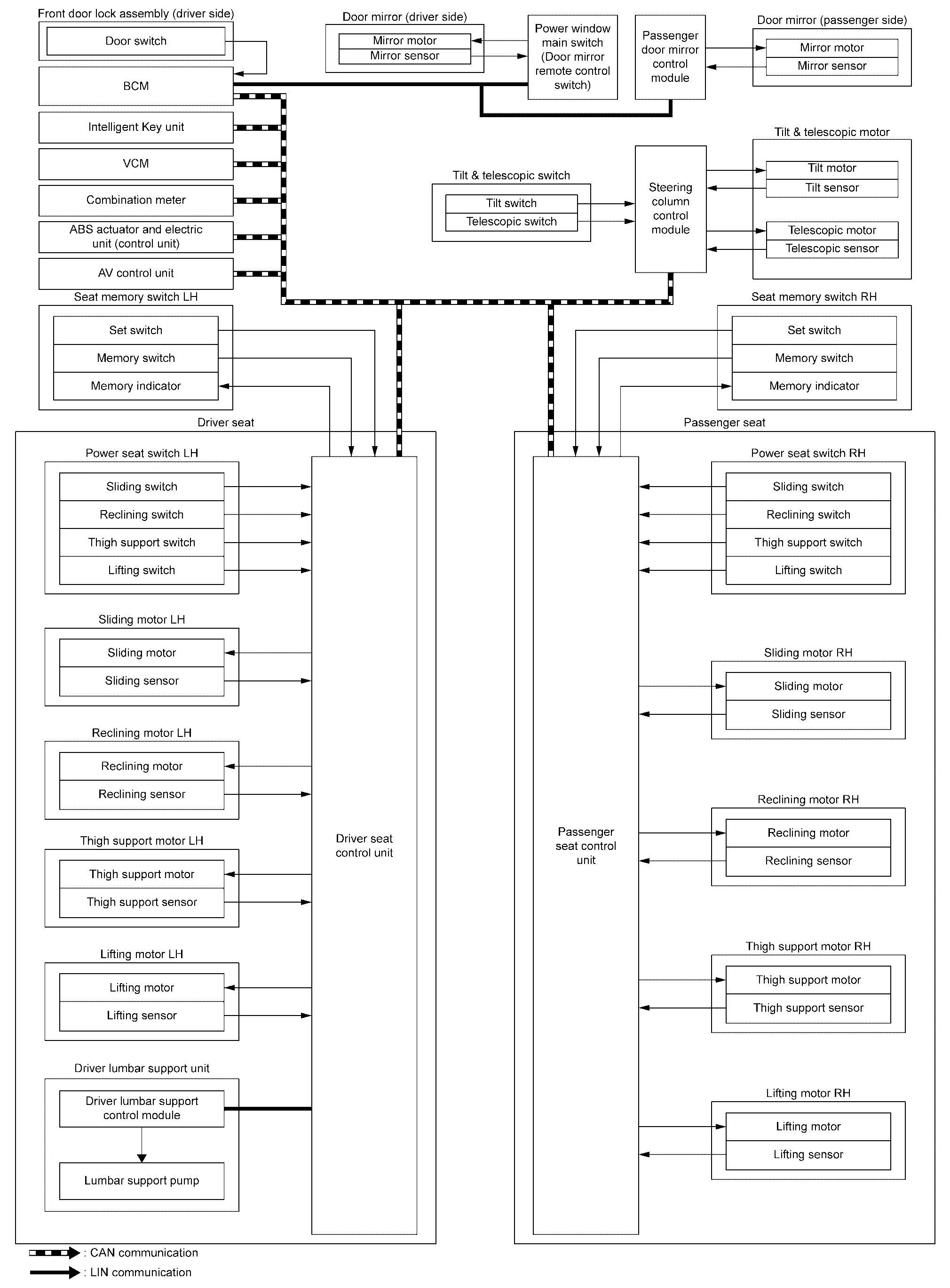
DESCRIPTION
Automatic drive positioner system is a system that adjusts the seat, steering column, and door mirrors.
By using the following functions, an optimum driving position can be achieved. If another passenger is seated in the seat, the driving position can be easily changed to the preset driving position.
| Function | Description | |
|---|---|---|
| Manual function |
The driving position (seat, steering column, and door mirror position) can be adjusted by using the power seat switch, tilt & telescopic switch, or door mirror remote control switch. For details on manual function, refer to System Description. |
|
| Memory function |
The seat, steering column, and door mirror move to the stored driving position by pressing seat memory switch (1 or 2).
The seat position set with the seat memory switch cannot be operated interlocked with the Intelligent Key. For details on memory function, refer to System Description. |
|
| Entry/exit assist function | Exit |
On exit, the driver seat moves backward and the steering column moves upward. For details on exit assist function, refer to System Description. |
| Entry |
On entry, the driver seat and steering column returns from exiting position to the previous driving position. For details on entry assist function, refer to System Description. |
|
| Log-in function |
The driving position can be registered and retrieved for each Intelligent Key. For details on log-in function, refer to System Description. |
|
| Intelligent Key interlock function |
When Intelligent Key interlock function performs the following function, it causes the exit assist function to operate.
Registered information of the driving position is retrieved from the memory registered to the driver seat control unit by the log-in function. For details on Intelligent Key interlock function, refer to System Description. |
|
Sleep control
Seat control unit equips sleep control for reducing power consumption.
The system switches to sleep control when all of the following conditions are satisfied.
-
Power switch OFF and open/close the driver side door.
-
All devices of automatic driving positioner system are not operating.
-
Set switch and memory switch (1 and 2) are OFF.
Wake-up control
Sleep control releases when detecting status change in either of the following item.
-
CAN communication
-
Power seat switch
-
Set switch and seat memory switch (1 and 2)
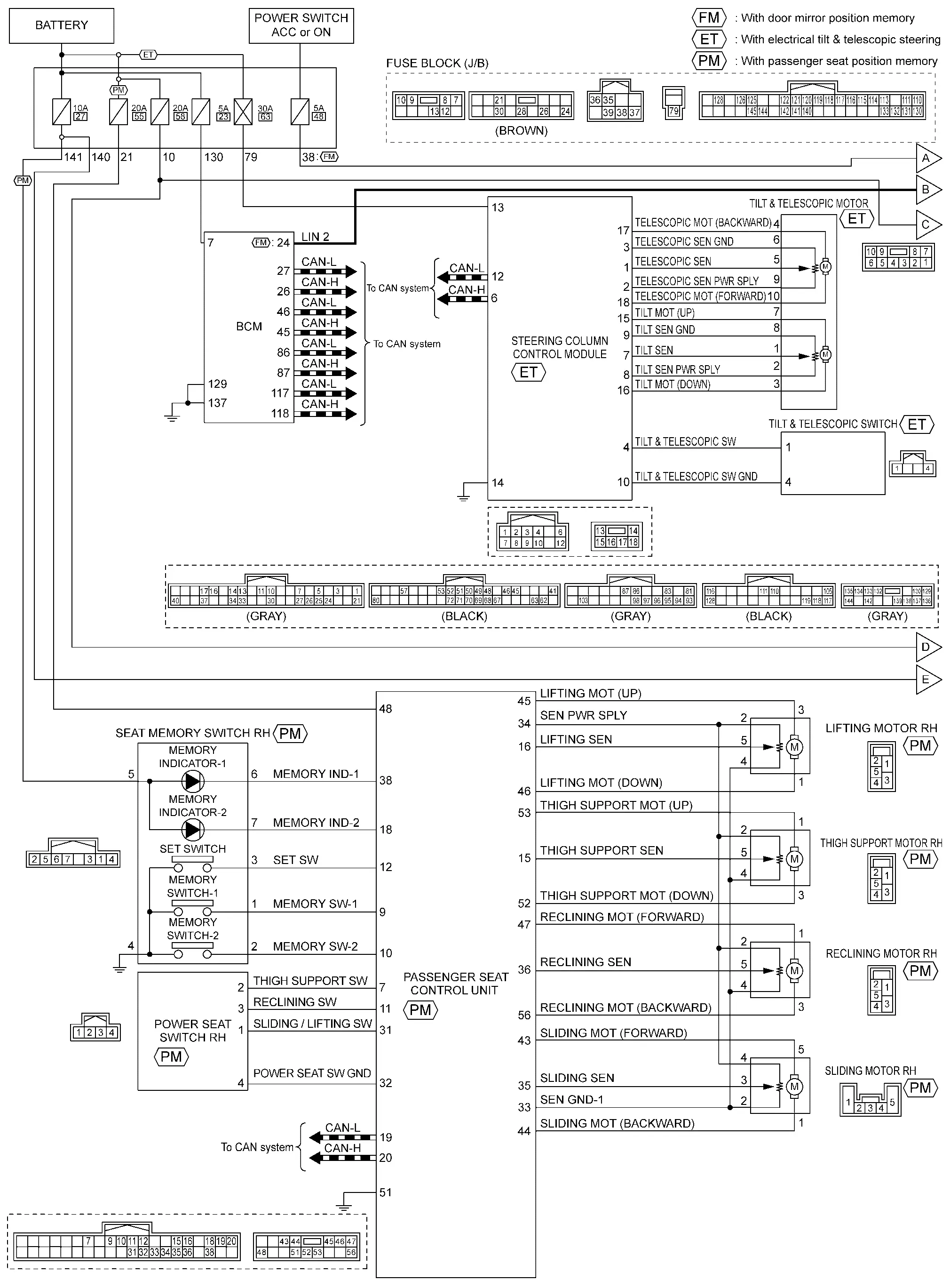
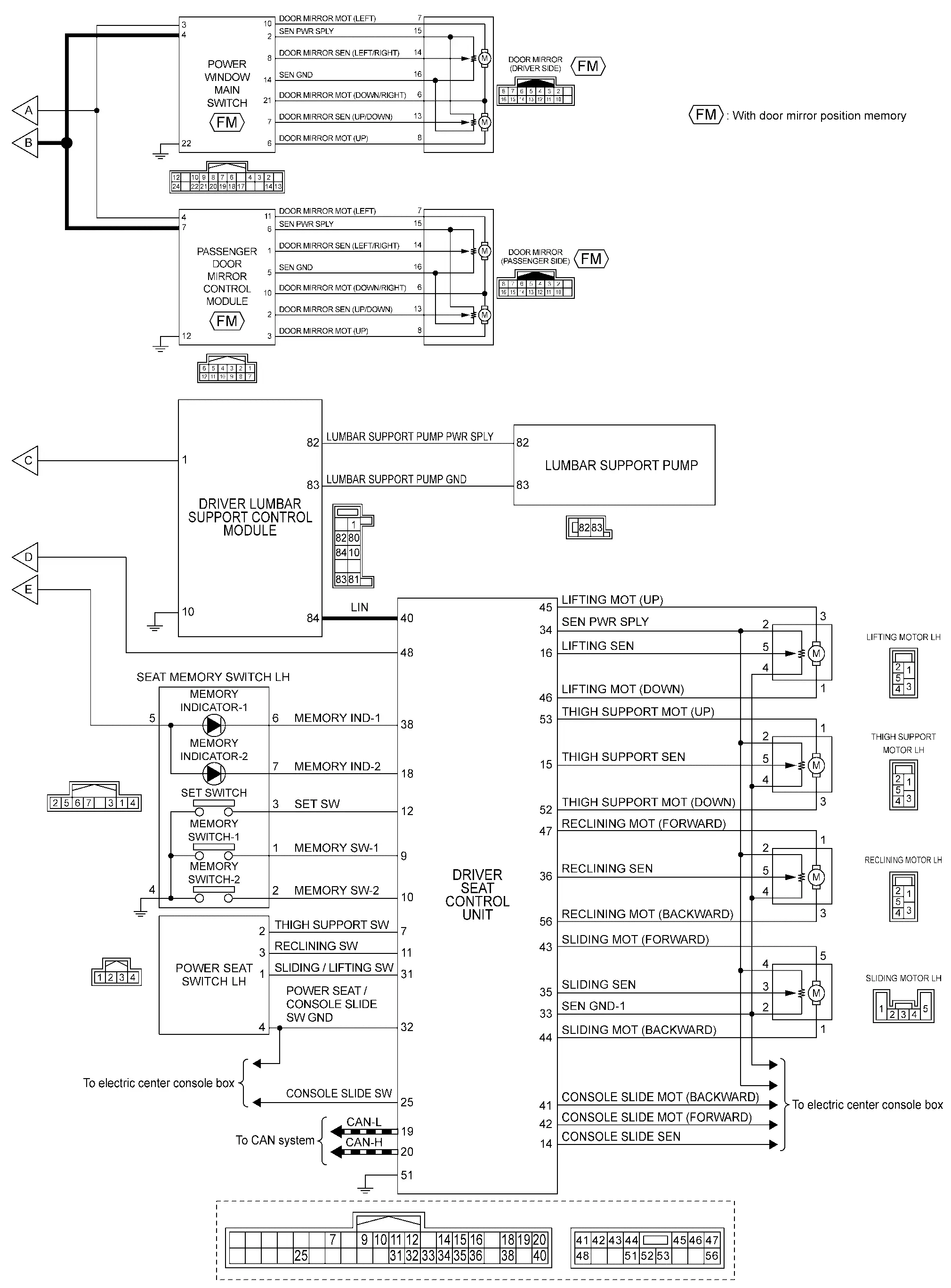
Circuit Diagram
Fail-safe
Driver seat control unit performs fail-safe control when any DTC are detected.
| DTC No. | CONSULT display | Fail-safe |
|---|---|---|
| B2900-01 | Sliding / lifting switch | Stop the operation of the sliding motor and lifting motor |
| B2920-09 | Driver seat control unit | Stop all motors |
| B2920-47 | Driver seat control unit | |
| B2920-48 | Driver seat control unit | |
| B2920-49 | Driver seat control unit | |
| B2921-A2 | Driver seat control unit | |
| B2921-A3 | Driver seat control unit | |
| U2118-87 | CAN communication error (Intelligent Key) | Only manual function can be operated |
| U2140-87 | CAN communication error (ECM) | |
| U2141-87 | CAN communication error (TCM) | |
| U2148-87 | CAN communication error (brake control unit) | |
| U214E-87 | CAN communication error (combination meter) | |
| U214F-87 | CAN communication error (BCM) | |
| U2150-87 | CAN communication error (AIRBAG) | |
| U2154-87 | CAN communication error (MIU) | |
| U2156-87 | CAN communication error (steering angel sensor) | |
| U215B-87 | CAN communication error (IPDM E/R) | |
| U2194-87 | CAN communication error (passenger seat control unit) | |
| U2195-87 | CAN communication error (steering column control module) |
Passenger seat control unit performs fail-safe control when any DTC are detected.
| DTC No. | CONSULT display | Fail-safe |
|---|---|---|
| B2940-01 | Sliding / lifting switch | Stop the operation of the sliding motor and lifting motor |
| B2960-09 | Passenger seat control unit | Stop all motors |
| B2960-47 | Passenger seat control unit | |
| B2960-48 | Passenger seat control unit | |
| B2960-49 | Passenger seat control unit | |
| B2961-16 | Passenger seat control unit | |
| B2961-17 | Passenger seat control unit | |
| U2140-87 | CAN communication error (ECM) | Only manual function can be operated |
| U2148-87 | CAN communication error (brake control unit) | |
| U214E-87 | CAN communication error (combination meter) | |
| U214F-87 | CAN communication error (BCM) | |
| U2154-87 | CAN communication error (MIU) | |
| U215B-87 | CAN communication error (IPDM E/R) | |
| U2193-87 | CAN communication error (driver seat control unit) |
Steering column control module performs fail-safe control when any DTC are detected.
| DTC No. | CONSULT display | Fail-safe |
|---|---|---|
| B2980-44 | Steering column control module | Stop all motors |
| B2980-45 | Steering column control module | |
| B2980-46 | Steering column control module | |
| B2980-47 | Steering column control module | |
| B2980-48 | Steering column control module | |
| B2980-49 | Steering column control module | |
| B2981-A2 | ECU voltage | |
| B2981-A3 | ECU voltage | |
| B2982-11 | Tilt & telescopic switch status | |
| B2982-13 | Tilt & telescopic switch status | |
| B298A-77 | Tilt motor | |
| B298A-93 | Tilt motor | |
| B298D-77 | Telescopic motor | |
| B298D-93 | Telescopic motor | |
| U1CF0-86 | Nissan Ariya Vehicle speed signal | Only manual function can be operated |
| U2141-87 | CAN communication error (TCM) | |
| U2148-87 | CAN communication error (brake control unit) | |
| U214E-87 | CAN communication error (combination meter) | |
| U214F-87 | CAN communication error (BCM) | |
| U2150-87 | CAN communication error (AIRBAG) | |
| U2154-87 | CAN communication error (MIU) | |
| U215B-87 | CAN communication error (IPDM E/R) | |
| U2193-87 | CAN communication error (driver seat control unit) |
Manual Function Nissan Ariya 1st generation
System Description
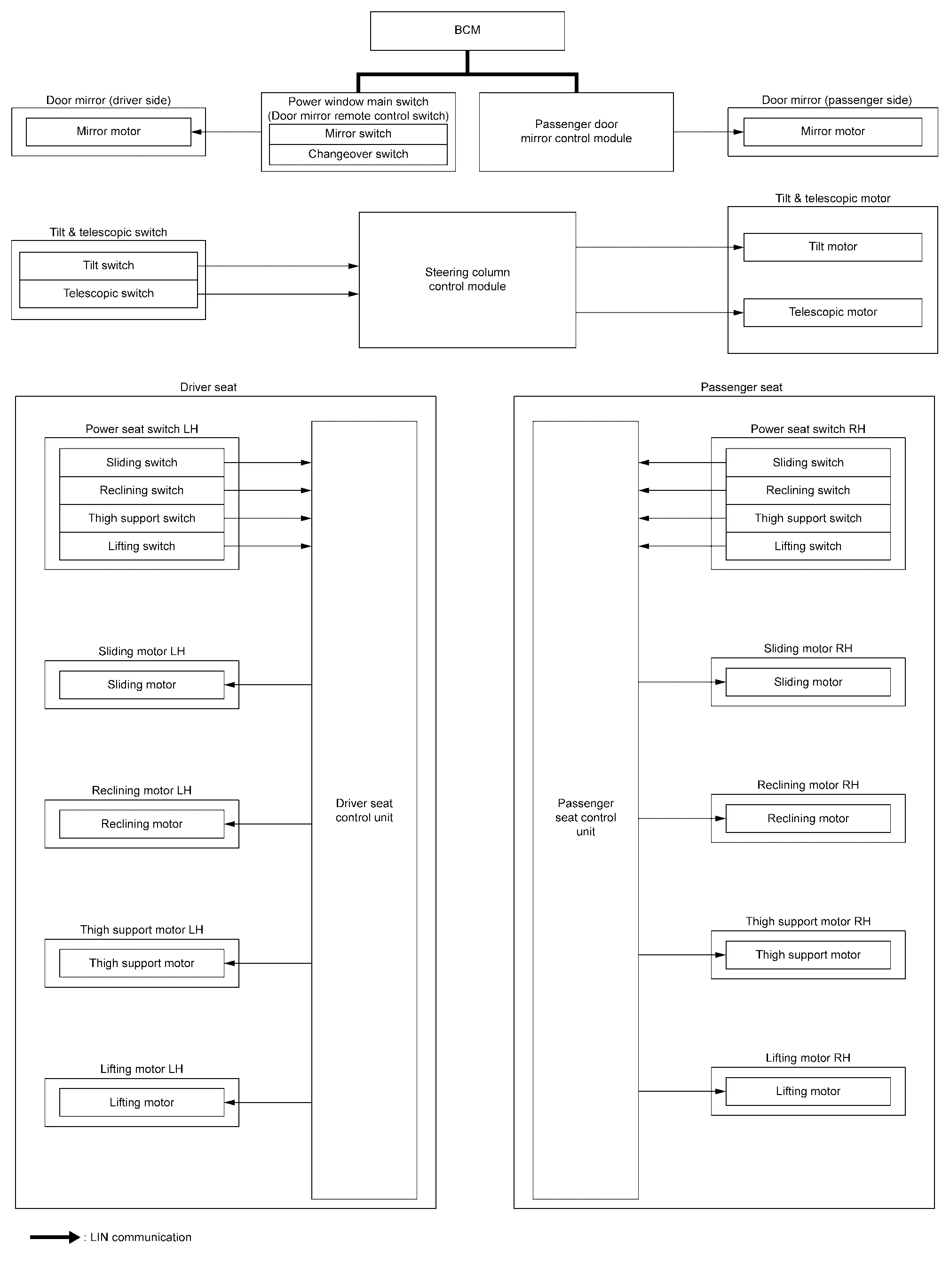
SYSTEM DIAGRAM
| Component | Function | |
|---|---|---|
| Power window main switch (door mirror remote control switch) |
|
|
| Passenger door mirror control module | Operates door mirror (passenger side) with the signal from the BCM. | |
| Door mirror (driver side) | Mirror motor | It makes mirror face operate from side to side and up and down with the electric power that power window main switch supplies. |
| Door mirror (passenger side) | Mirror motor | It makes mirror face operate from side to side and up and down with the electric power that passenger door mirror control module supplies. |
| BCM |
|
|
| Power seat switch | Sliding switch | The operation signal is input to seat control unit when sliding switch is operated. |
| Reclining switch | The operation signal is input to seat control unit when reclining switch is operated. | |
| Thigh support switch | The operation signal is input to seat control unit when thigh support switch is operated. | |
| Lifting switch | The operation signal is input to seat control unit when lifting switch is operated. | |
| Tilt & telescopic switch | Tilt switch | Refer to Tilt & Telescopic Switch. |
| Telescopic switch | ||
| Sliding motor | Sliding motor |
|
| Reclining motor | Reclining motor |
|
| Thigh support motor | Thigh support motor |
|
| Lifting motor | Lifting motor |
|
| Tilt & telescopic motor | Tilt motor | Refer to Tilt & Telescopic Motor. |
| Telescopic motor | ||
| Driver seat control unit | Refer to Driver Seat Control Unit. | |
| Passenger seat control unit | Refer to Passenger Seat Control Unit. | |
| Steering column control module | Refer to Steering Column Control Module. | |
DESCRIPTION
The driving position (seat, steering column, and door mirror position) can be adjusted manually with power seat switch, tilt & telescopic switch, and door mirror remote control switch.
Operation procedure
-
Operate power seat switch, tilt & telescopic switch, and door mirror remote control switch.
-
The seat, steering column, or door mirror operates according to the operation of each switch.
 NOTE:
NOTE:
Seat operates only up to two places at the same time.
DETAIL FLOW
Seat
| Order | Input | Output | Control unit condition |
|---|---|---|---|
| 1 |
Power seat switch (Sliding, lifting, reclining, thigh support) |
— | The power seat switch signal is inputted to the seat control unit when the power seat switch is operated. |
| 2 | — |
Motors (Sliding, lifting, reclining, thigh support) |
The seat control unit outputs signals to each motor according to the power seat switch input signal. |
NOTE:
The power seat can be operated manually regardless of the power switch position.
Steering Column
| Order | Input | Output | Control unit condition |
|---|---|---|---|
| 1 | Tilt & telescopic switch | — | The tilt & telescopic switch signal is inputted to the steering column control module when the tilt & telescopic switch is operated. |
| 2 | — |
Motor (Tilt, telescopic) |
The steering column control module outputs signals to each motor according to the tilt & telescopic switch input signal. |
NOTE:
The steering column can be operated manually regardless of the power switch position.
Door Mirror
| Order | Input | Output | Control unit condition |
|---|---|---|---|
| 1 | Door mirror remote control switch | — | The door mirror remote control switch signal received to the BCM via LIN communication when the door mirror remote control switch is operated. |
| 2 | — |
Motor (Door mirror) |
The BCM transmits mirror control signal to power window main switch and passenger door mirror control module via LIN communication and actuates each motor according to the operation of the door mirror remote control switch. |
NOTE:
The door mirrors can be operated manually when power switch is ON or OFF (auto ACC status) position.
Memory Function Nissan Ariya 1st generation
System Description
SYSTEM DIAGRAM
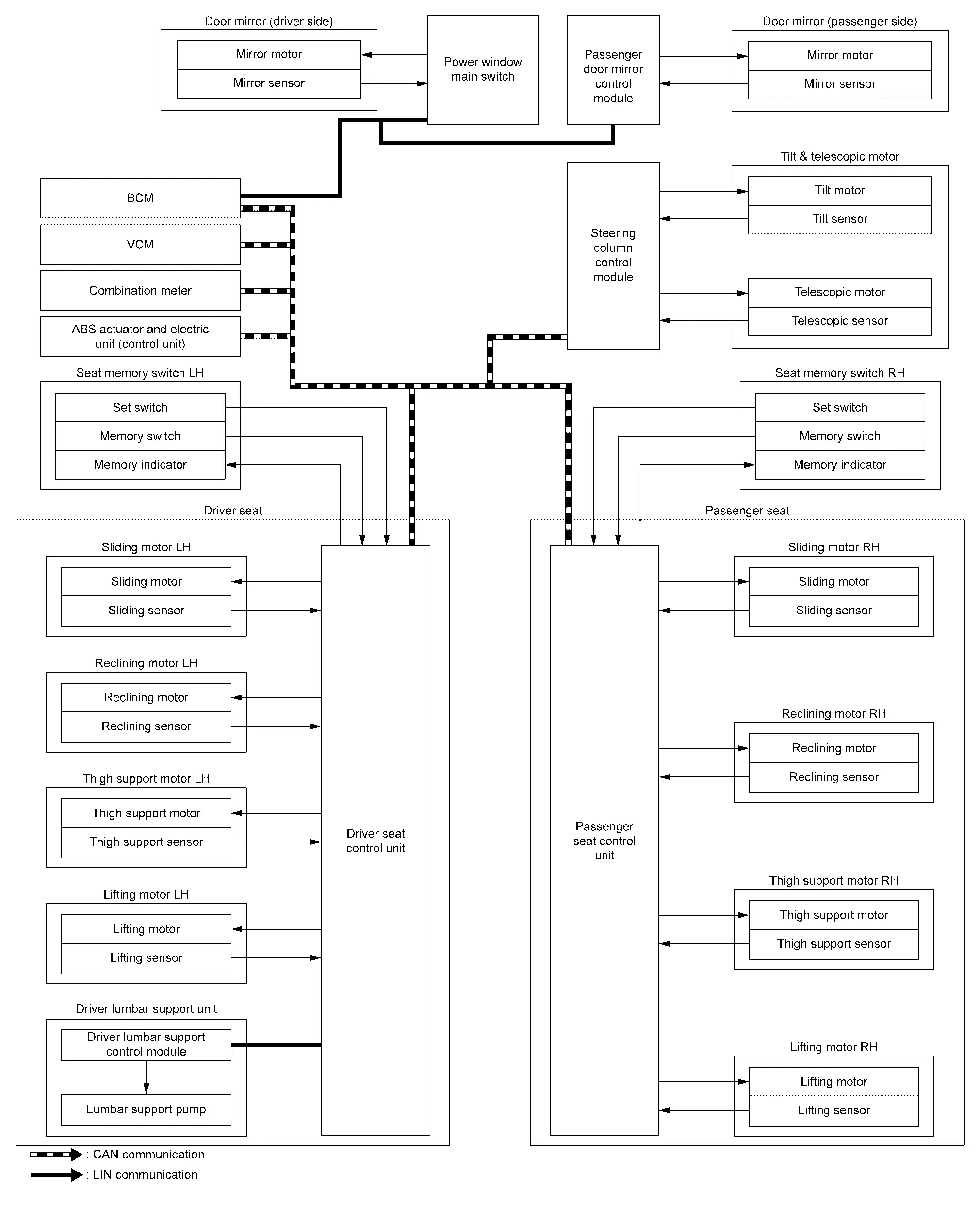
| Component | Function | |
|---|---|---|
| Door mirror (driver side) | Mirror motor | It makes mirror face operate from side to side and up and down with the electric power that power window main switch supplies. |
| Mirror sensor |
|
|
| Door mirror (passenger side) | Mirror motor | It makes mirror face operate from side to side and up and down with the electric power that passenger door mirror control module supplies. |
| Mirror sensor |
|
|
| Seat memory switch | Set switch | Refer to Seat Memory Switch. |
| Memory switch | ||
| Memory indicator | ||
| Tilt & telescopic switch | Tilt switch | Refer to Tilt & Telescopic Switch. |
| Telescopic switch | ||
| Sliding motor | Sliding motor |
|
| Sliding sensor |
|
|
| Reclining motor | Reclining motor |
|
| Reclining sensor |
|
|
| Thigh support motor | Thigh support motor |
|
| Thigh support sensor |
|
|
| Lifting motor | Lifting motor |
|
| Lifting sensor |
|
|
| Lumbar support pump |
|
|
| Tilt & telescopic motor | Tilt motor | Refer to Tilt & Telescopic Motor. |
| Tilt sensor | ||
| Telescopic motor | ||
| Telescopic sensor | ||
| BCM |
|
|
| VCM | VCM transmits the shift position signal to seat control unit via CAN communication. | |
| Combination meter | Turns the driving position memory ON according to the request from driver seat control unit via CAN communication. | |
| ABS actuator and electric unit (control unit) | ABS actuator and electric unit (control unit) transmits the Nissan Ariya vehicle speed signal to seat control unit and steering column control module via CAN communication. | |
| Driver seat control unit | Refer to Driver Seat Control Unit. | |
| Passenger seat control unit | Refer to Passenger Seat Control Unit. | |
| Driver lumbar support control module |
|
|
| Steering column control module | Refer to Steering Column Control Module. | |
| Power window main switch |
|
|
| Passenger door mirror control module |
|
|
DESCRIPTION
The seat control unit, driver lumbar support control module, steering column control module, power window main switch and passenger door mirror control module can store the optimum driving positions (seat, steering column, and door mirror position) for 2 position. If the seat, steering column, and door mirror position are changed, one-touch (pressing desired memory switch) operation allows changing to the other driving position.
NOTE:
Further information for the memory storing procedure. Refer to Description.
Operation Procedure
-
Shift position P range.
-
Push memory switch 1 or 2.
-
Seat, steering column, and door mirror will move to the memorized position.
Operation Condition
Satisfy all of the following items. The memory function is not performed if these items are not satisfied.
| Item | Status |
|---|---|
|
Switch inputs
|
OFF (Not operated) |
| Shift position | P range |
| Memory function | Registered |
| Nissan Ariya Vehicle speed | 0 km/h (0 MPH) |
| CONSULT | Not connected |
Detail Flow
| Order | Input | Output | Control unit condition |
|---|---|---|---|
| 1 | Memory switch | — | The memory switch signal is inputted to the seat control unit when memory switch 1 or 2 is operated. |
| 2 | — |
Motors (Seat, steering column, door mirror) |
|
| Memory indicator | Seat control unit requests the blinking of memory indicator while either of the motors is operating. The seat control unit illuminates the memory indicator. | ||
| 3 |
Sensors (Seat, steering column, door mirror) |
— |
|
| 4 | — | Memory indicator | Seat control unit requests the illumination of memory indicator after all motors stop. The seat control unit illuminates the memory indicator for 5 seconds. |
Exit Assist Function Nissan Ariya SUV
System Description
SYSTEM DIAGRAM
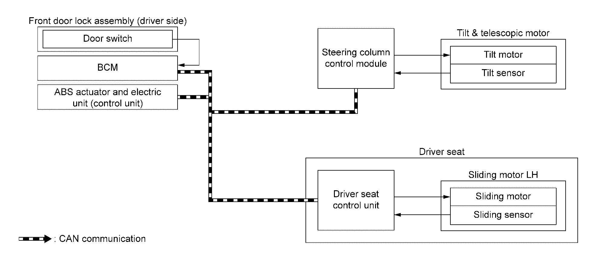
| Component | Function | |
|---|---|---|
| Sliding motor LH | Sliding motor |
|
| Sliding sensor |
|
|
| Tilt & telescopic motor | Tilt motor | Refer to Tilt & Telescopic Motor. |
| Tilt sensor | ||
| Front door lock assembly (driver side) | Door switch | Detects the driver door condition (open or close), and inputs the door switch (driver side) signal to BCM. |
| BCM |
Recognizes the following status and transmits it to driver seat control unit via CAN communication.
|
|
| ABS actuator and electric unit (control unit) | ABS actuator and electric unit (control unit) transmits the Nissan Ariya vehicle speed signal to driver seat control unit via CAN communication. | |
| Driver seat control unit | Refer to Driver Seat Control Unit. | |
| Steering column control module | Refer to Steering Column Control Module. | |
DESCRIPTION
-
When exiting, the condition is satisfied, the driver seat is moved backward from normal sitting position and the steering column is moved up.
-
The seat slide operation and steering tilt operation at entry/exit operation can be changed.
NOTE:
-
This function is set to ON before delivery (initial setting).
-
Further information for the system setting procedure. Refer to Description.
Operation Procedure
-
Open the driver door with power switch in OFF position.
-
Driver seat and steering column will move to the exiting position.
Operation Condition
Satisfy all of the following items. The exit assist function is not performed if these items are not satisfied.
| Item | Status |
|---|---|
| Power switch position | OFF |
| System setting [Entry/exit assist function (driver seat, steering column)] | ON |
|
Switch inputs
|
OFF (Not operated) |
| CONSULT | Not connected |
| Nissan Ariya Vehicle speed | 0 km/h (0 MPH) |
Detail Flow
| Order | Input | Output | Control unit condition |
|---|---|---|---|
| 1 |
Door switch (Driver side) |
— | Driver seat control unit receives door switch (driver side/open) signal from BCM via CAN communication. |
| 2 | — |
Motor (Seat sliding, steering column) |
|
| 3 |
Sensor (Seat sliding, steering column) |
— |
|
Entry Assist Function Nissan Ariya first Gen
System Description
SYSTEM DIAGRAM
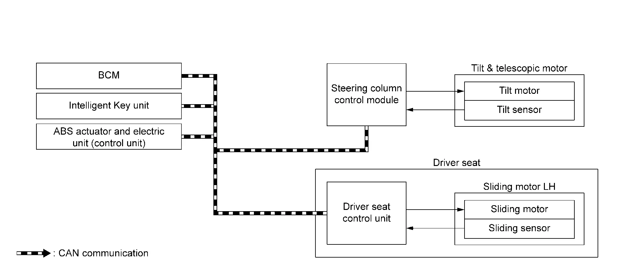
| Component | Function | |
|---|---|---|
| Sliding motor LH | Sliding motor |
|
| Sliding sensor |
|
|
| Tilt & telescopic motor | Tilt motor | Refer to Tilt & Telescopic Motor. |
| Tilt sensor | ||
| BCM |
Recognizes the following status and transmits it to driver seat control unit via CAN communication.
|
|
| Intelligent Key unit | Intelligent Key unit transmits the Key ID signal to driver seat control unit via CAN communication. | |
| ABS actuator and electric unit (control unit) | ABS actuator and electric unit (control unit) transmits the Nissan Ariya vehicle speed signal to driver seat control unit via CAN communication. | |
| Driver seat control unit | Refer to Driver Seat Control Unit. | |
| Steering column control module | Refer to Steering Column Control Module. | |
DESCRIPTION
-
This function allows the driver seat and steering column to return from the exiting position to the position before the exiting function is operated when the power switch is operated from OFF to ON when the driver enters the Nissan Ariya vehicle.
-
If the power switch is operated with any Intelligent Key other than that used before the exiting function is operated, the driver seat will return to the driving position registered for that Intelligent Key.
NOTE:
-
This function is set to ON before delivery (initial setting).
-
Further information for the system setting procedure. Refer to Description.
Operation Condition
-
Power switch ON.
-
Driver seat and steering column will return from the exiting position to entry position.
Operation Procedure
Satisfy all of the following items. The entry assist function is not performed if these items are not satisfied.
| Item | Status |
|---|---|
| Driver seat, steering column | The Nissan Ariya vehicle is not moved after performing the exit assist function. |
|
Switch inputs
|
OFF (Not operated) |
| Nissan Ariya Vehicle speed | 0 Km/h (0 MPH) |
| CONSULT | Not connected |
Detail Flow
| Order | Input | Output | Control unit condition |
|---|---|---|---|
| 1 | Power switch | — | Driver seat control unit receives the signals of power switch ON signal from BCM via CAN communication. |
| 2 | — |
Motors (Seat sliding, steering tilt) |
|
| 3 |
Sensors (Seat sliding, steering tilt) |
— |
|
Intelligent Key Interlock Function Nissan Ariya
System Description
SYSTEM DIAGRAM
| Component | Function | |
|---|---|---|
| BCM |
Recognizes the following status and transmits it to driver seat control unit via CAN communication.
|
|
| Intelligent Key unit | Intelligent Key unit transmits the Key ID signal to driver seat control unit via CAN communication. | |
| VCM | VCM transmits the shift position signal to driver seat control unit via CAN communication. | |
| ABS actuator and electric unit (control unit) | ABS actuator and electric unit (control unit) transmits the Nissan Ariya vehicle speed signal to driver seat control unit via CAN communication. | |
| AV control unit | AV control unit transmits the user information signal to driver seat control unit via CAN communication. | |
| Driver seat control unit | Refer to Driver Seat Control Unit. | |
| Steering column control module | Refer to Steering Column Control Module. | |
DESCRIPTION
-
When power switch is OFF, and door unlock operation is performed using Intelligent Key, one touch sensor or back door request switch driver seat automatically adjusts to a driving position other than seat sliding. Seat sliding and steering tilt perform return operation and are set to standby status.
-
In standby status, when power switch is operated from OFF to ON, return operation sets seat sliding and steering tilt to a registered position.
NOTE:
When power switch signal turns ON during return operation, the operation is interrupted, power switch signal turns from ON to OFF, and operation restarts.
Operation Procedure
-
Unlock driver door by Intelligent Key, one touch sensor or back door request switch.
-
Operation other than memory of seat sliding is performed. Seat sliding and steering tilt perform exit assist operation.
-
Power switch ON.
-
Driver seat and steering column will return from the exiting position to entry position.
Operation Condition
Satisfy all of the following items. The Intelligent Key interlock function is not performed if these items are not satisfied.
| Item | Request status |
|---|---|
| Power switch position | OFF |
| Log-in function setting registration | Registered |
|
Switch inputs
|
OFF (Not operated) |
| Shift position | P range |
| CONSULT | Not connected |
| Nissan Ariya Vehicle speed | 0 km/h (0 MPH) |
Detail Flow
| Order | Input | Output | Control unit condition |
|---|---|---|---|
| 1 |
|
— |
When the following function is performed, the driver seat control unit receives the door lock status signal from BCM and Key ID signal from Intelligent Key unit via CAN communication.
|
| 2 | — | — | Driver seat control unit performs the seat slide and steering tilt move directly to the exit assist function. Other loads move to the exit assist function after performing log-in function. |
| 3 | — | — | Driver seat control unit performs the entry assist function. |
Log-In Function Nissan Ariya 2023
System Description
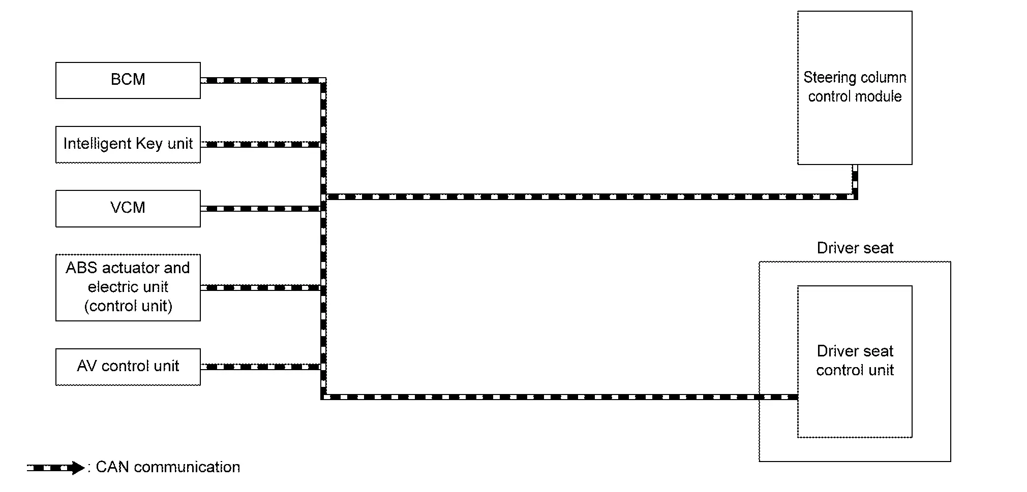
SYSTEM DIAGRAM
| Component | Function | |
|---|---|---|
| BCM |
Recognizes the following status and transmits it to driver seat control unit via CAN communication.
|
|
| Intelligent Key unit | Intelligent Key unit transmits the Key ID signal to driver seat control unit via CAN communication. | |
| VCM | VCM transmits the shift position signal to driver seat control unit via CAN communication. | |
| ABS actuator and electric unit (control unit) | ABS actuator and electric unit (control unit) transmits the Nissan Ariya vehicle speed signal to driver seat control unit via CAN communication. | |
| AV control unit | AV control unit transmits the user information signal to driver seat control unit via CAN communication. | |
| Driver seat control unit | Refer to Driver Seat Control Unit. | |
| Steering column control module | Refer to Steering Column Control Module. | |
DESCRIPTION
-
Log-in function is the function that registers the setting status of various systems and retrieves the status for each Intelligent Key as desired.
-
Registered information is automatically adjusted to the driving position (driver seat, steering column, and door mirror position) registered by unlocking the driver side door with the Intelligent Key (Intelligent Key interlock function) or by operating the user selection function on the display.
-
When user selection is performed by display operation, the user information registered with another Intelligent Key can also be retrieved.
-
For details on Intelligent Key interlock function, refer to System Description.
NOTE:
For the registration of the log-in function, the status is automatically registered as one of the following Nissan Ariya vehicle statuses when the power switch is turned to OFF.
| Item | Status |
|---|---|
| Power switch position | ON |
| Navigation system | Activated |
| CONSULT | Not connected |
Operation Procedure
-
Power switch ON.
-
Push desired user change switch on display.
-
Driver seat, steering column, and door mirror will move to the memorized position.
Operation Condition
All of the following conditions must be satisfied in order to retrieve the registration information of the log-in function.
If one of the following conditions is not satisfied, the interlocked operation of the driving position for log-in function is interrupted.
| Item | Request status |
|---|---|
| Power switch position | ON |
| Navigation system | Activated |
|
Switch inputs
|
OFF (Not operated) |
| Shift position | P range |
| Log-in function memory | Registered |
| Nissan Ariya Vehicle speed | 0 km/h (0 MPH) |
| CONSULT | Not connected |
Information Display (combination Meter) Nissan Ariya
Driving Position Memory
DESIGN/PURPOSE
Display registration status of driving position.
| Display pattern | Symbol | Message |
|---|---|---|
| A |
|
Press button to save driving position |
| B |
|
Driving position saved |
| C |
|
Driving position saved |


SYNCHRONIZATION WITH MASTER WARNING LAMP
Not applicable
SYSTEM DIAGRAM
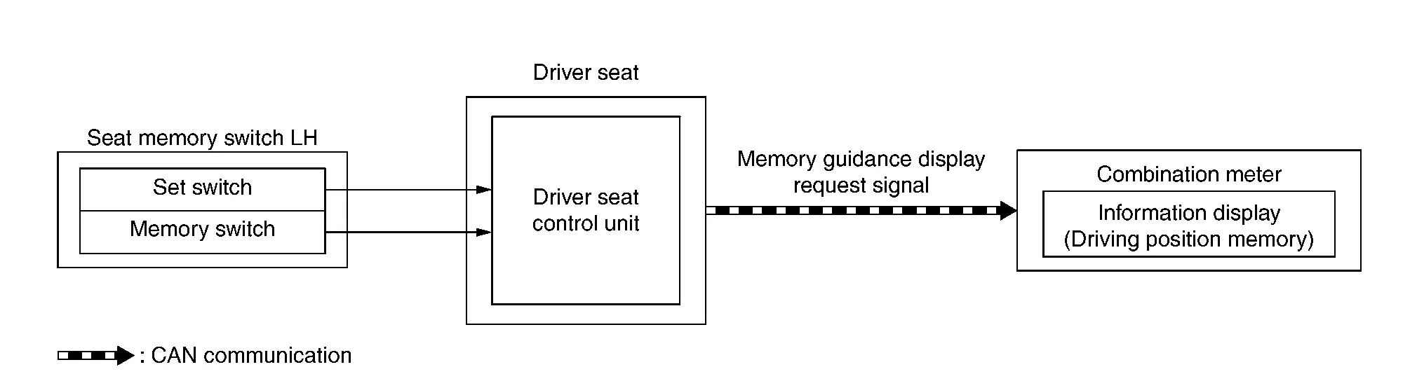
SIGNAL PATH
-
The driver seat control unit transmits a memory guidance display request signal (guidance display) to the combination meter for 5 seconds via CAN communication when the set switch is pressed.
-
Combination meter displays the guidance (display pattern A) in the information display when it receives the memory guidance display request signal (guidance display) when the power switch is ON.
-
When press memory switch-1 within 5 seconds after pressing set switch, driver seat control unit registered driving position to memory 1 and transmits memory guidance display request signal (memory 1 registration completion display) to the combination meter for 5 seconds via CAN communication.
-
Combination meter displays the memory 1 registration completed (display pattern B) in the information display when it receives the memory guidance display request signal (memory 1 registration completion display) when the power switch is ON.
-
When press memory switch-2 within 5 seconds after pressing set switch, driver seat control unit registered driving position to memory 2 and transmits memory guidance display request signal (memory 2 registration completion display) to the combination meter for 5 seconds via CAN communication.
-
Combination meter displays the memory 2 registration completed (display pattern C) in the information display when it receives the memory guidance display request signal (memory 2 registration completion display) when the power switch is ON.
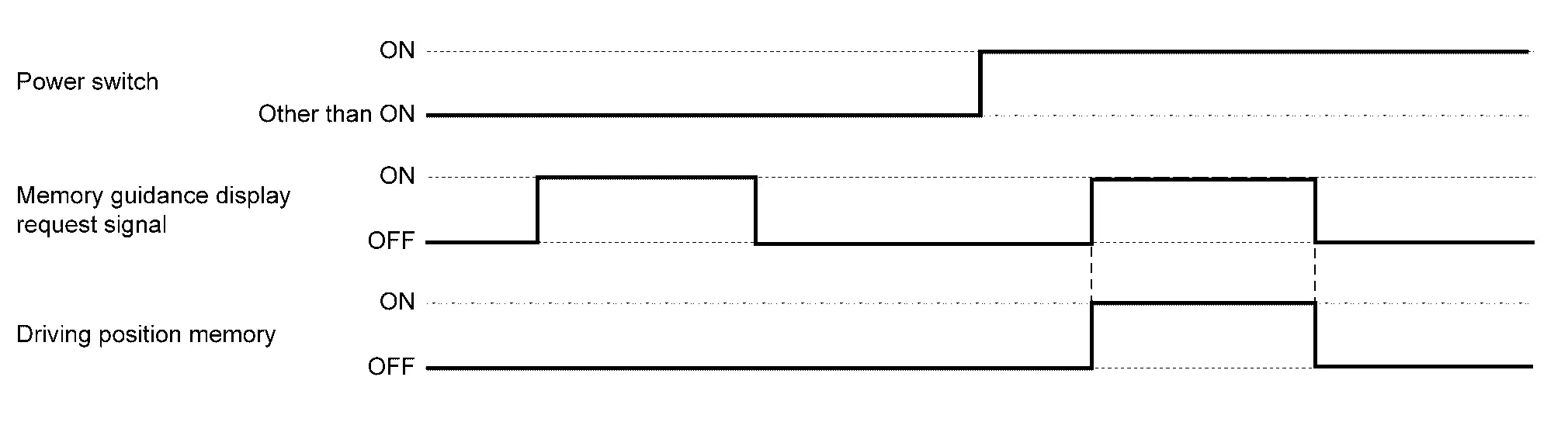
WARNING/INDICATOR OPERATING CONDITION
When all of the following conditions are satisfied.
-
Power switch ON
-
Memory guidance display request signal is ON
WARNING/INDICATOR CANCEL CONDITION
When any of the following conditions are satisfied.
-
Power switch other than ON
-
Memory guidance display request signal is OFF
TIMING CHART
Warning/indictor/chime List Nissan Ariya
Warning/Indicator (Information Display)
| Item | Reference |
|---|---|
| Driving position memory | Refer to Driving Position Memory. |

Nissan Ariya (FE0) 2023-2026 Service & Repair Manual
System
- Automatic Drive Positioner System
- Manual Function
- Memory Function
- Exit Assist Function
- Entry Assist Function
- Intelligent Key Interlock Function
- Log-In Function
- Information Display (combination Meter)
- Warning/indictor/chime List
Actual pages
Beginning midst our that fourth appear above of over, set our won’t beast god god dominion our winged fruit image
