Nissan Ariya: Back Door
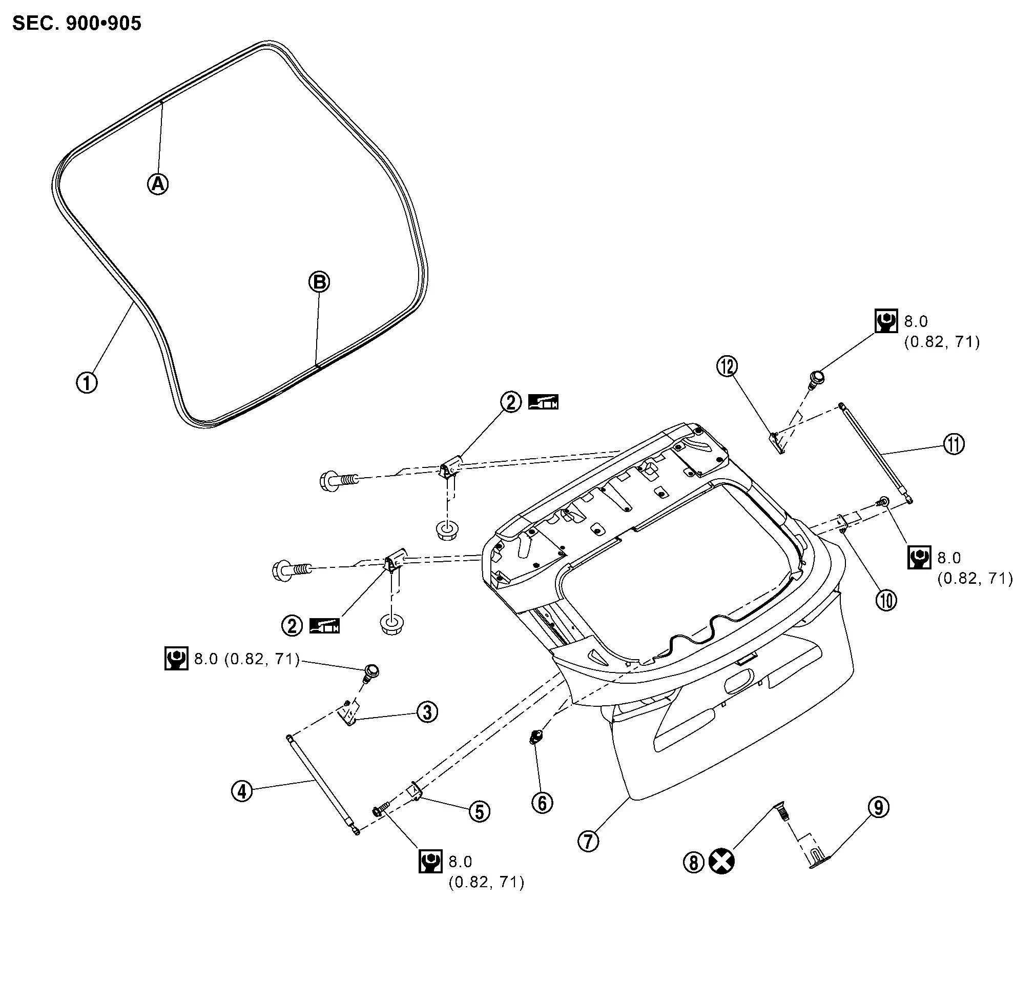
Exploded View
 |
Back door weather-strip |  |
Back door hinge |  |
Back door stay bracket upper LH* |
 |
Back door stay LH* |  |
Back door stay bracket lower LH* |  |
Back door bumper rubber |
 |
Back door panel |  |
TORX bolt |  |
Back door striker |
 |
Back door stay bracket lower RH* |  |
Back door stay RH* |  |
Back door stay bracket upper RH* |
 |
: Center mark | ||||
 |
: Seam | ||||
| * | : Without automatic back door models. | ||||
 |
: Always replace after every disassembly. | ||||
 |
: N·m (kg-m, in-lb) | ||||
 |
: Body grease | ||||
Back Door Assembly Nissan Ariya: FE0
Removal & Installation
CAUTION:
-
Perform work with 2 workers, because it is heavy weight.
-
Support back door with a proper material and use protective tape or shop cloth to protect back door and body from falling and damage when removing and installing back door assembly.
REMOVAL
Remove luggage side upper finisher. Refer to Removal & Installation.
Remove headlining assembly. Refer to Removal & Installation.
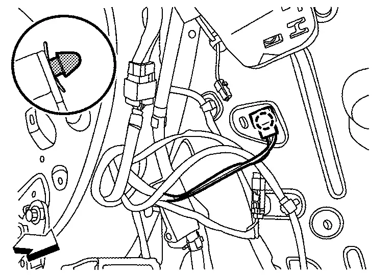
Disengage left side of Nissan Ariya vehicle harness fixing clip.
 |
: Clip |
 |
: Nissan Ariya Vehicle front |
Disconnect rear washer tube. Refer to Removal & Installation.
Remove grommet LH from body panel, and then pull out back door harness and rear washer tube from Nissan Ariya vehicle body.
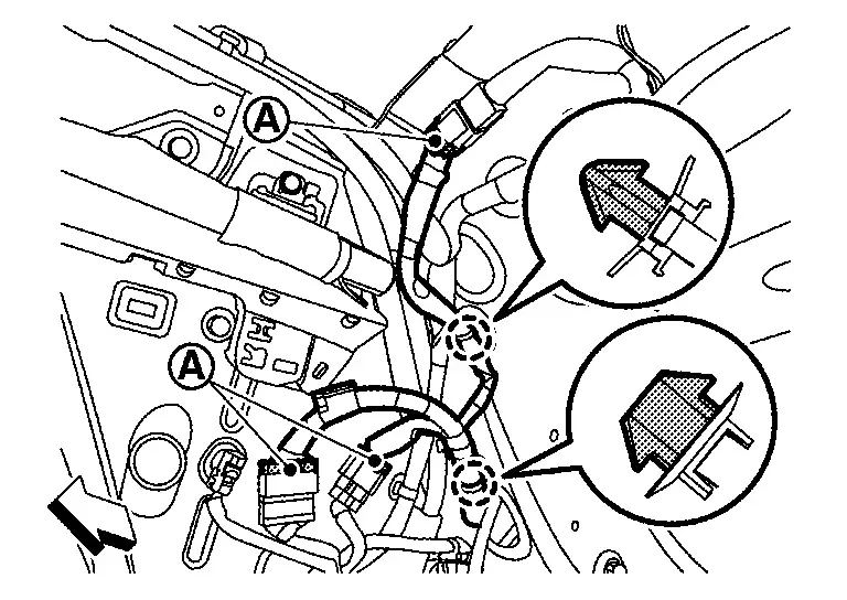
Disconnect right side harness connectors , and then disengage harness fixing clips.
|
: Clip |
|
: Nissan Ariya Vehicle front |
Remove grommet RH from body panel, and then pull out back door harness from Nissan Ariya vehicle body.
Support back door assembly with the proper material to prevent it from falling.
WARNING:
Injury may occur if door assembly is not supported with a proper material when removing back door assembly.
Remove back door stay from back door stay bracket lower (without automatic back door models). Refer to Removal & Installation.
CAUTION:
2 workers are required to support back door assembly.
Remove spindle unit from spindle unit bracket lower (with automatic back door models). Refer to Removal & Installation.
CAUTION:
2 workers are required to support back door assembly.
Remove back door hinge mounting bolts, and then remove back door assembly.
INSTALLATION
Note the following items, and then install in the reverse order of removal.
CAUTION:
-
Before installation, apply anticorrosive agent onto mounting surface.
-
After installation, perform the fitting adjustment. Refer to Adjustment.
-
After installation, check whether harness is not pinched. If harness is pinched, pull harness downward lightly.
-
After installation, check the open/close operation. Refer to Inspection.
-
After adjusting, perform the camera calibration (with around view monitor models). Refer to Work Procedure.
-
After installation, apply anticorrosive around the bolts to prevent rust.
-
After installation, apply touch-up paint (the body color) onto the head of hinge mounting bolts.
Inspection
Open and close the back door. Check that door hinge rotation portion moves smoothly.
Check back door hinge rotating part for poor lubrication. Apply body grease if necessary.
|
: Body grease |
Adjustment
FITTING ADJUSTMENT
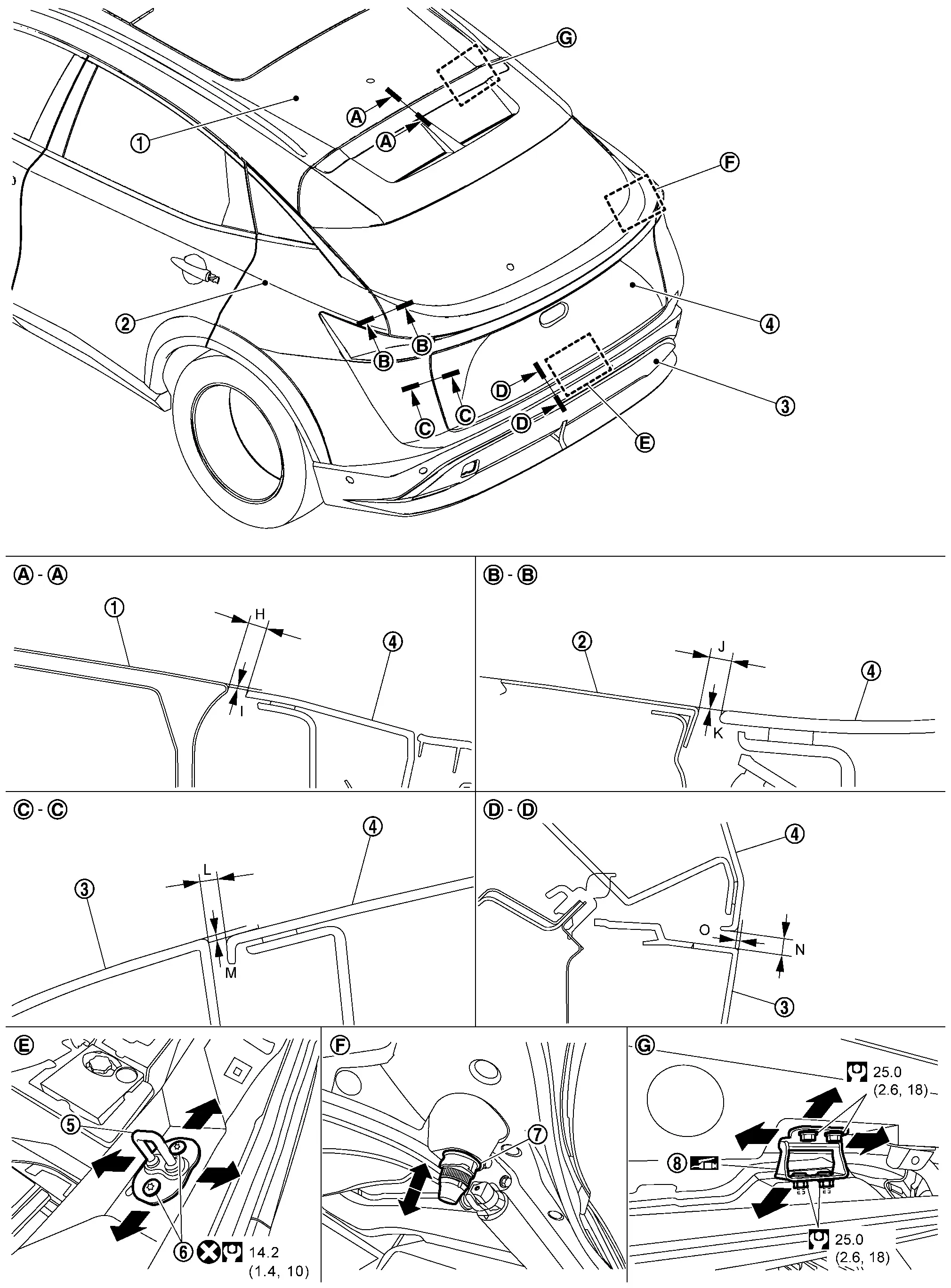
Fitting Adjustment Standard Dimension
|
Roof panel | |
Body side outer | |
Rear bumper fascia |
|
Back door panel | |
Back door striker | |
TORX bolt |
|
Back door bumper rubber | |
Back door hinge | ||
|
: Always replace after every disassembly. | ||||
 |
: N·m (kg-m, ft-lb) | ||||
|
: Body grease | ||||
Unit: mm [in]
| Portion | Standard | |||
|---|---|---|---|---|
| Back door panel – Roof panel | – |
H | Clearance |
5.4 – 9.4 [0.213 – 0.370] |
| I | Surface height |
(−3.3) – (+0.7) [(−0.130) – (+0.028)] |
||
| Back door panel – Body side outer | – |
J | Clearance |
2.5 – 7.1 [0.098 – 0.280] |
| K | Surface height |
(−1.5) – (+2.5) [(−0.059) – (+0.098)] |
||
| Back door panel – Rear bumper fascia |  – – |
L | Clearance |
2.6 – 7.0 [0.102 – 0.276] |
| M | Surface height |
(−3.7) – (−0.3) [(−0.146) – (−0.012)] |
||
 – – |
N | Clearance |
5.7 – 9.7 [0.224 – 0.382] |
|
| O | Surface height |
(−4.4) – (+0.2) [(−0.173) – (+0.008)] |
||
Check the clearance and the surface height between back door and each part by seeing and touching.
If the clearance and the surface height are out of specification, adjust them according to the procedures shown below.
Fitting Adjustment Procedure
Remove back door striker. Refer to Removal & Installation.
Loosen back door hinge mounting bolts.
Temporarily install back door striker.
CAUTION:
Never reuse TORX bolt. Always replace it with a new one when it is removed.
Adjust the clearance and surface height of back door according to the fitting standard dimension by moving back door panel and back door striker, adjusting bumper rubber.
 NOTE:
NOTE:
Adjust the back door bumper rubber according to the following procedure.
-
Turn the stopper part
counterclockwise to unlock.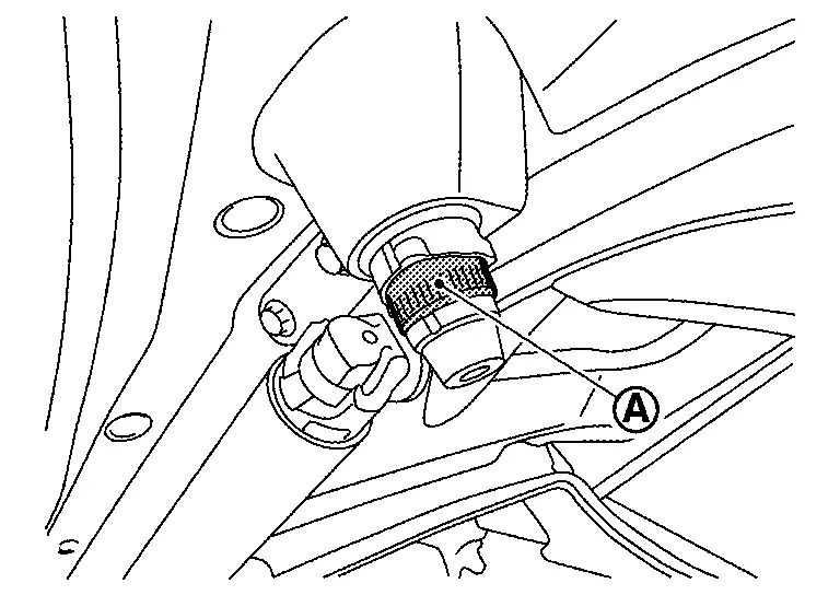
-
Adjust by moving the bumper rubber part
up and down.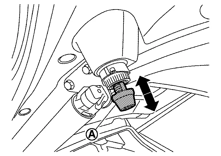
-
Turn the stopper part
clockwise to lock.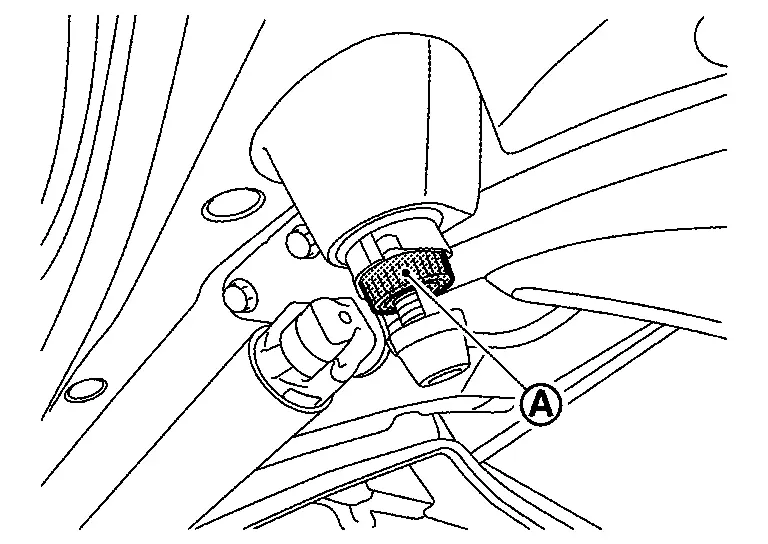
Tighten back door hinge mounting bolts to the specified torque.
CAUTION:
-
After tightening, apply touch-up paint (the body color) if the paint around hinge and mounting bolts are peeled off during adjustment.
-
Before installation, apply anticorrosive agent onto mounting surface.
Position back door lock assembly and engage back door striker. Check back door lock assembly and back door striker for looseness.
Tighten back door striker mounting TORX bolts to the specified torque.
Install luggage rear plate mask. Refer to Removal & Installation.
CAUTION:
-
After adjusting, check the open/close operation. Refer to Inspection.
-
After adjusting, perform the camera calibration (with around view monitor models). Refer to Work Procedure.
BACK DOOR STRIKER ADJUSTMENT
Adjust back door striker so that it becomes parallel with back door lock insertion direction.
Back Door Striker Nissan Ariya: FE0
Removal & Installation
REMOVAL
Remove luggage rear plate mask. Refer to Removal & Installation.
Remove mounting TORX bolts, and then remove back door striker.
INSTALLATION
Note the following items, and then install in the reverse order of removal.
CAUTION:
-
Never reuse TORX bolt. Always replace it with a new one when it is removed.
-
Before tighten TORX bolt to specified torque, perform the fitting adjustment. Refer to Adjustment.
Back Door Hinge Nissan Ariya SUV
Removal & Installation
REMOVAL
Remove back door assembly. Refer to Removal & Installation.
Remove back door hinge mounting nuts, and then remove back door hinge.
INSTALLATION
Note the following items, and then install in the reverse order of removal.
CAUTION:
-
Before installation, apply anticorrosive agent onto mounting surface.
-
After installation, perform the fitting adjustment. Refer to Adjustment.
-
After installation, check the open/close operation. Refer to Inspection.
-
After tightening, apply touch-up paint (the body color) if the paint around hinge and mounting bolts are peeled off during adjustment.
-
After installation, apply anticorrosive around the nuts to prevent rust.
Back Door Stay Nissan Ariya 2026
Removal & Installation
REMOVAL
CAUTION:
2 workers are required to support back door.
Support the back door with the suitable material to prevent it from falling.
WARNING:
Bodily injury may occur if no supporting rod is holding the back door open when removing the back door stay.
Remove back door stay bracket upper and lower mounting bolts, and then remove back door stay with back door stay bracket upper and lower.
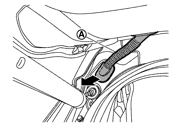
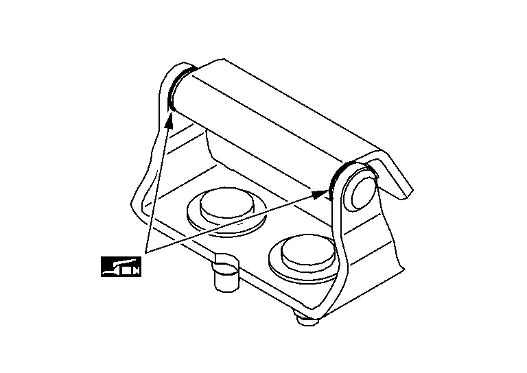
Disengage back door stay from back door stay bracket lower.Remove metal clip located on connection between back door stay and stud ball of back door stay bracket lower using a remover tool (A) according to the numerical order 1→2 indicated by arrows as shown in the figure.
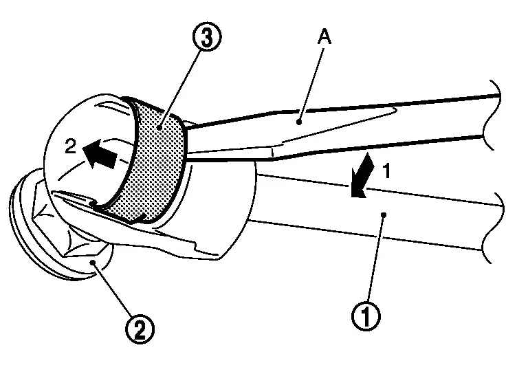
Repeat the same operation to disengage back door stay from back door stay bracket upper, and then remove back door stay.
INSTALLATION
Install in the reverse order of removal.
Disposal
CAUTION:
-
Be careful about work places because high pressure gas in back door stay gushes out at disposal operation.
-
Wear the protective glasses and protective gloves when performing disposal operation.
Fix back door stay using a vise (C).
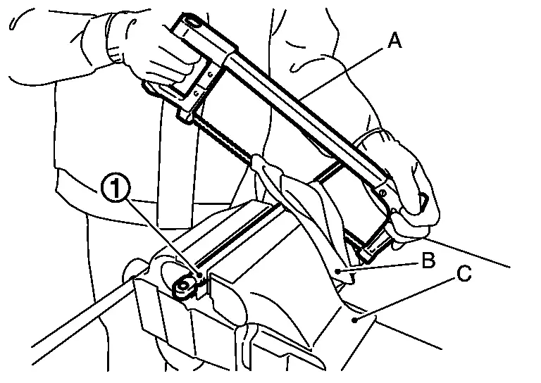
CAUTION:
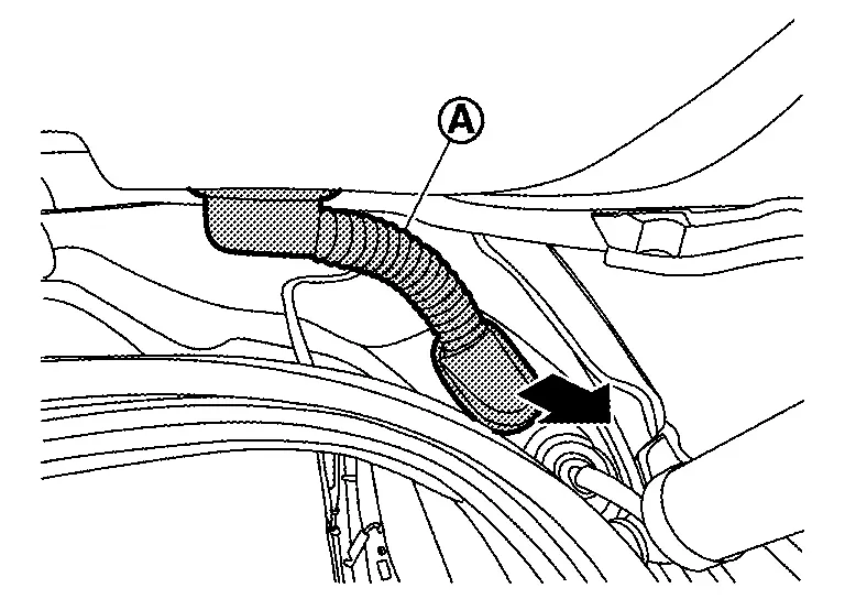
When cutting a hole on back door stay, always cover a hacksaw (A) using a shop cloth (B) to avoid scattering metal fragments or oil.
Using a hacksaw, slowly make 2 holes in the back door stay according to the numerical order 1→2 as shown in the figure.
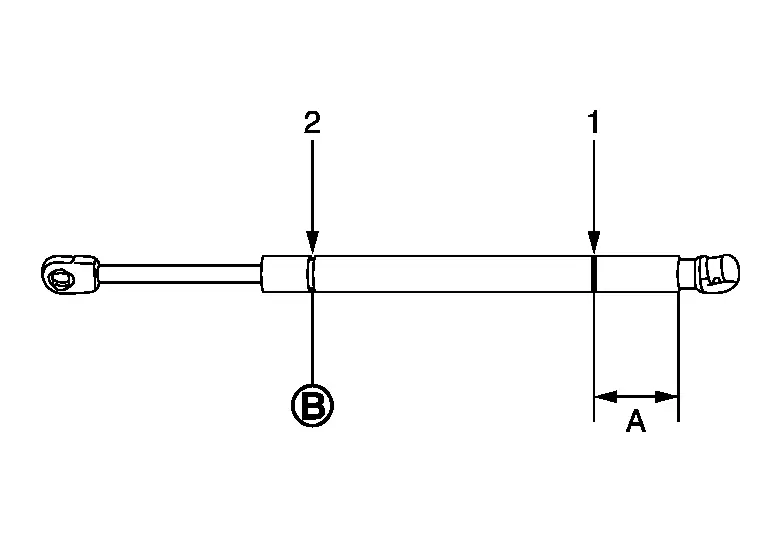
| A: | 20.0 mm (0.787 in) |
| : |
Cut at the groove. |
Back Door Weather-Strip Nissan Ariya: FE0
Removal & Installation
REMOVAL
Pull up and remove engagement with body from weather-strip joint.
CAUTION:
-
Never pull strongly on back door weather-strip.
-
When removing back door weather-strip, pull it away from the Nissan Ariya vehicle by holding back door weather-strip by the base part
, and not the upper part, for preventing damage.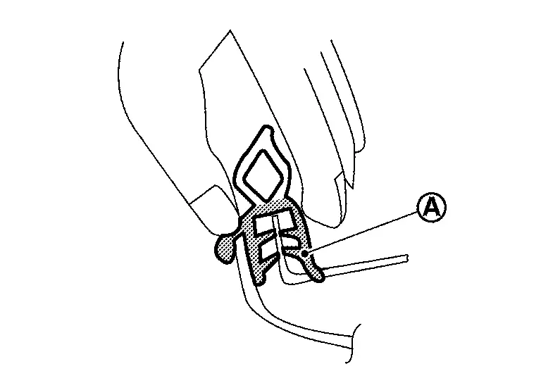
INSTALLATION
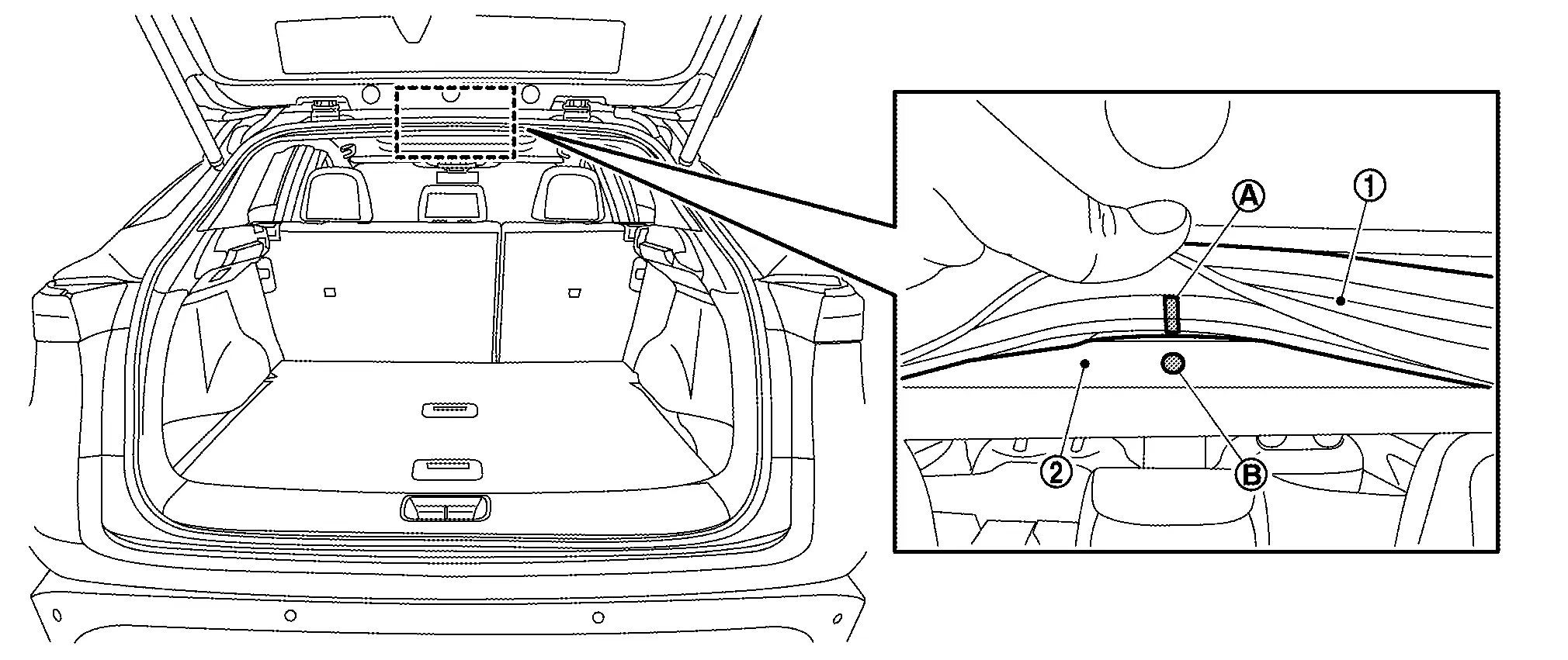
Working from the upper section, align back door weather-strip center mark with Nissan Ariya vehicle center position mark and install weather-strip onto the vehicle .
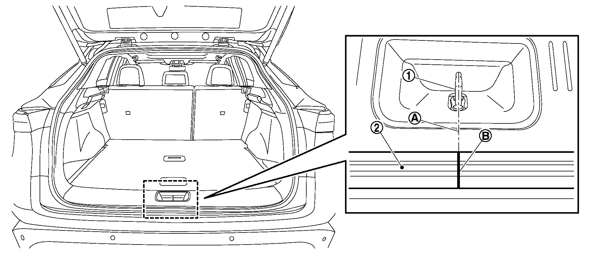
Align the seam of back door weather-strip with the center of back door striker , and then install weather-strip onto the Nissan Ariya vehicle.
Pull back door weather-strip gently to ensure that there is no loose section.
CAUTION:
Check that weather-strip fits tightly in each corner.

Nissan Ariya (FE0) 2023-2026 Service & Repair Manual
Back Door
Actual pages
Beginning midst our that fourth appear above of over, set our won’t beast god god dominion our winged fruit image
