Nissan Ariya: Busbar
2wd Nissan Ariya 2026
Exploded View
DISASSEMBLY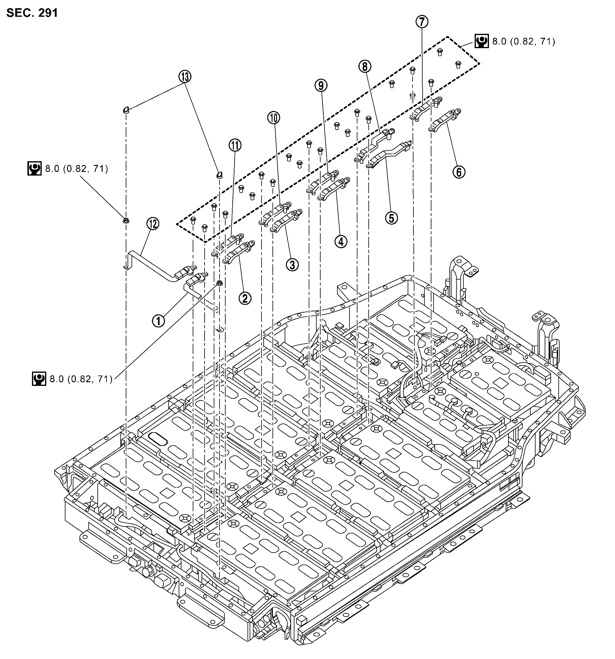
 |
Busbar 2 |  |
Busbar 3 |  |
Busbar 4 |
 |
Busbar 5 |  |
Busbar 6 |  |
Busbar 7 |
 |
Busbar 8 |  |
Busbar 15 |  |
Busbar 16 |
 |
Busbar 17 |  |
Busbar 18 |  |
Busbar 19 |
 |
Nut cap | ||||
 |
: N·m (kg-m, in-lb) |
BUSBAR LAYOUT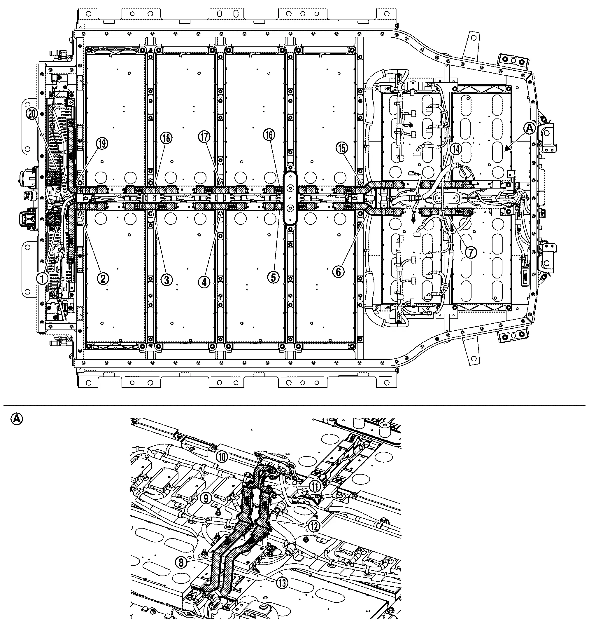
|
Busbar 1 | |
Busbar 2 | |
Busbar 3 |
|
Busbar 4 | |
Busbar 5 | |
Busbar 6 |
|
Busbar 7 | |
Busbar 8 | |
Busbar 9 |
|
Busbar 10 | |
Busbar 11 | |
Busbar 12 |
|
Busbar 13 |  |
Busbar 14 |  |
Busbar 15 |
 |
Busbar 16 |  |
Busbar 17 |  |
Busbar 18 |
 |
Busbar 19 |  |
Busbar 20 | ||
 |
: Service bracket ASSY |
Disassembly & Assembly
DANGER: Because hybrid vehicles and electric vehicles contain a high voltage battery, there is a risk of electric shock, electric leakage, or similar accidents if the Nissan Ariya vehicle is handled incorrectly. Be sure to follow the correct work procedures when performing inspection and maintenance.
WARNING:
-
Be sure to remove the service plug in order to shut off the high voltage circuits before performing inspection or maintenance of high voltage system harnesses and parts.
-
Be sure to put the removed service plug in pocket and carry it or store it in a tool box or other container so that another person does not accidentally connect it while work is in progress.
-
Be sure to put on insulating protective gear before beginning work on the high voltage system.
-
Clearly identify the persons responsible for high voltage work and ensure that other persons do not touch the Nissan Ariya vehicle. When not working, cover high voltage components with an anti-static cover sheet or similar item to prevent contact with other persons.
-
Refer to PRECAUTIONS FOR HIGH VOLTAGE : Precautions.
-
If the battery pack is to be disassembled, be sure to remove the Li-ion battery controller for preventing electric shock, fire, and damage to parts.
CAUTION:
There is the possibility of a malfunction occurring if the vehicle is changed to READY status while the service plug is removed. Therefore do not change the Nissan Ariya vehicle to READY status unless instructed to do so in the Service Manual.
ENVIRONMENT FOR LI-ION BATTERY DISASSEMBLY WORK
Must be an indoor environment.
-
The environment must utilize a shutter or other means to shut out the outside environment and prevent rain, snow, dust, or other substances from entering.
-
The environment must not cause the intrusion of sweat during work, or cause condensation to occur due to high temperature or humidity.
Metal powder, grease, and other foreign substances must not enter.
-
The indoor environment must also prevent metal powder, grease, and other foreign substances from entering due to maintenance performed on other Nissan Ariya vehicles and other sources during disassembly work.
-
During disassembly without internal work, temporarily close the battery pack upper case or cover it with an insulating cover.
The floor must be dry.
-
The floor must not be wet as a result of factors such as Nissan Ariya vehicle entry during rain or snow.
Work space
-
The work space must be approximately the size of one entire Nissan Ariya vehicle.
-
Take appropriate countermeasures so that persons other than the operator do not enter the work space, such as by placing signs indicating that disassembly work is in progress.
Standard fire fighting equipment
-
Always place a standard fire fighting equipment in the disassembly work area.
-
Depending on type of fire (Nissan Ariya vehicle or battery) use standard fire fighting equipment (water or extinguisher).
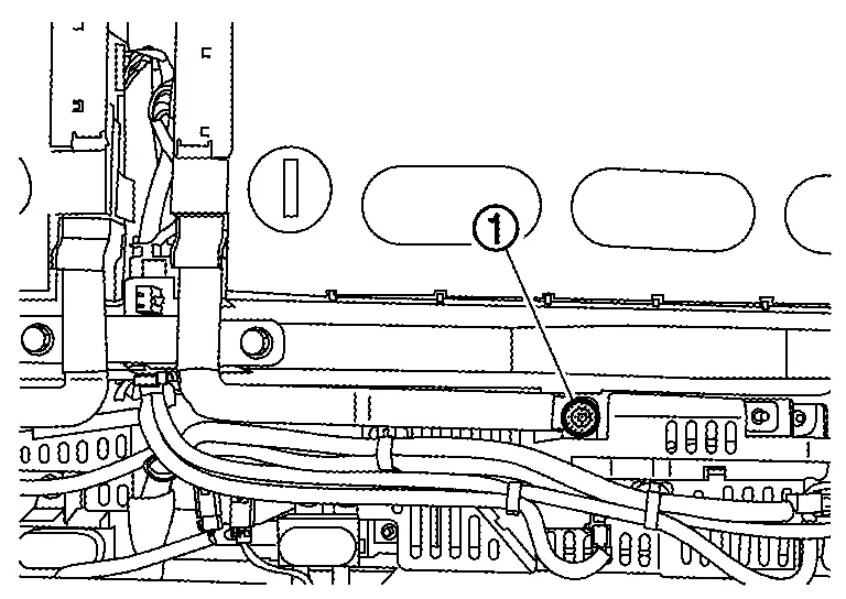
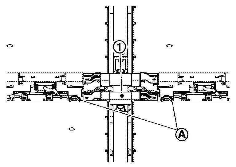
Busbar 1 and Busbar 20:
Refer to Disassembly & Assembly.
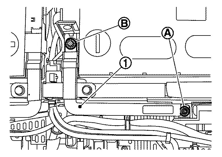
Busbar 8 and Busbar 13:
Refer to Disassembly & Assembly.
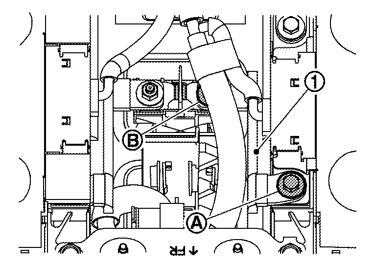
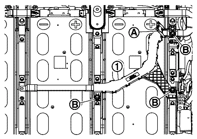
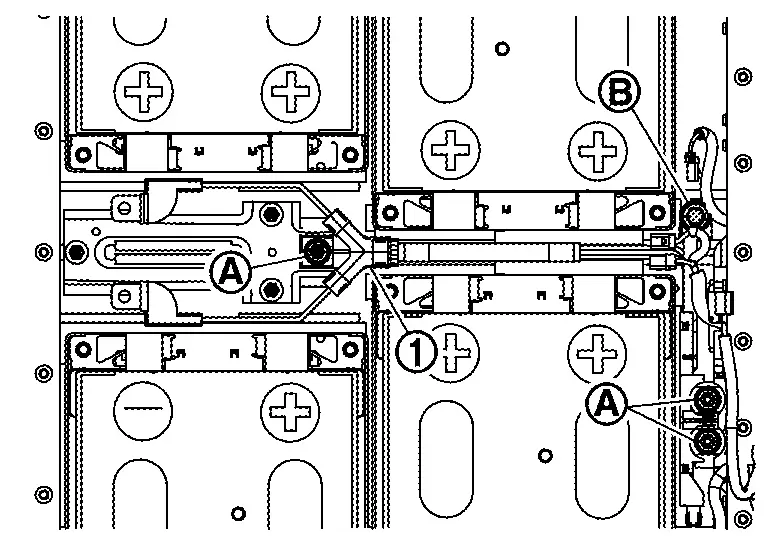
Busbar 2 and Busbar 19:
Disassembly
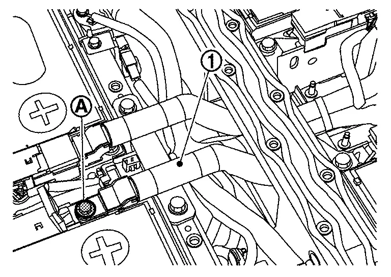
Remove nut cap .
WARNING:
To prevent electric shock, wear insulated protective gear and use insulated tools.


 NOTE:
NOTE:
The figure shows busbar 2.
Remove nut and then remove busbar 2 .
WARNING:
To prevent electric shock, wear insulated protective gear and use insulated tools.
NOTE:
The figure shows busbar 2.
Remove busbar 19 in the same way.
Assembly
Note the following items, and assemble in the reverse order of disassembly.
DANGER:-
There is the danger of electric shock caused by contact with the terminals. Be sure to wear insulated protective gear and use insulated tools.
-
Because there is a danger of electric shock and fire, never allow bus bar to contact a wrong terminal.
-
If bus bar contacts a wrong terminal, the circuit becomes energized and a short may occur.
-
Always keep the busbar cover closed until immediately before the installation of busbar.
-
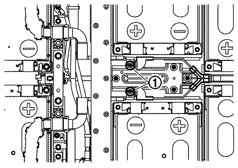
Busbar 3, Busbar 4, Busbar 17 and Busbar 18:
Disassembly
Remove bolts and then remove busbar 3 .
WARNING:
To prevent electric shock, wear insulated protective gear and use insulated tools.
NOTE:
The figure shows busbar 3.
Remove the other busbars in the same way.
Assembly
Note the following items, and assemble in the reverse order of disassembly.
DANGER:-
There is the danger of electric shock caused by contact with the terminals. Be sure to wear insulated protective gear and use insulated tools.
-
Because there is a danger of electric shock and fire, never allow bus bar to contact a wrong terminal.
-
If bus bar contacts a wrong terminal, the circuit becomes energized and a short may occur.
-
Always keep the bus bar cover closed until immediately before the installation of bus bar.
-
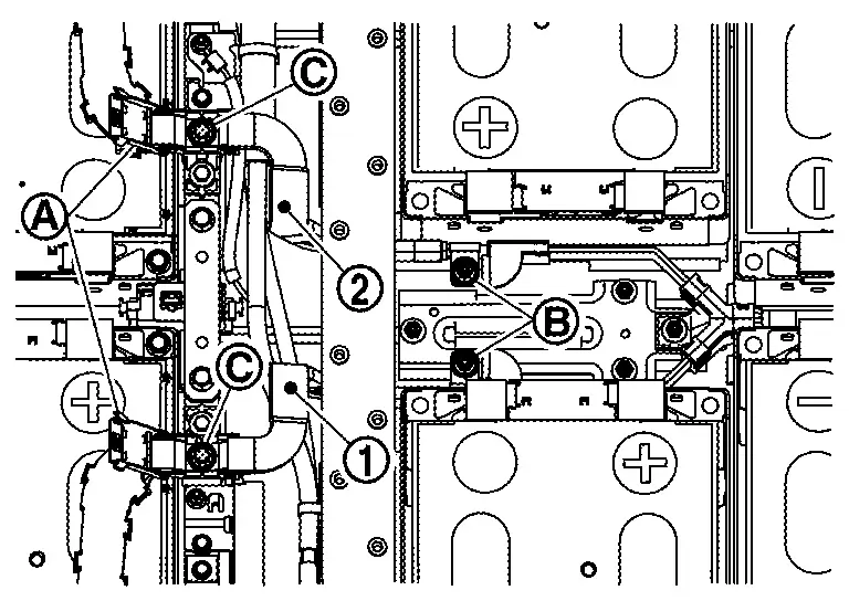
Busbar 5 and Busbar 16:
Disassembly
Remove bracket .
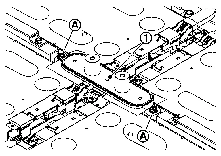
|
: Bolts |
WARNING:
To prevent electric shock, wear insulated protective gear and use insulated tools.
Remove bolts and then remove busbar 5.
WARNING:
To prevent electric shock, wear insulated protective gear and use insulated tools.
NOTE:
The figure shows busbar 3.
Remove busbar 16 in the same way.
Assembly
Note the following items, and assemble in the reverse order of disassembly.
DANGER:-
There is the danger of electric shock caused by contact with the terminals. Be sure to wear insulated protective gear and use insulated tools.
-
Because there is a danger of electric shock and fire, never allow bus bar to contact a wrong terminal.
-
If bus bar contacts a wrong terminal, the circuit becomes energized and a short may occur.
-
Always keep the bus bar cover closed until immediately before the installation of bus bar.
-
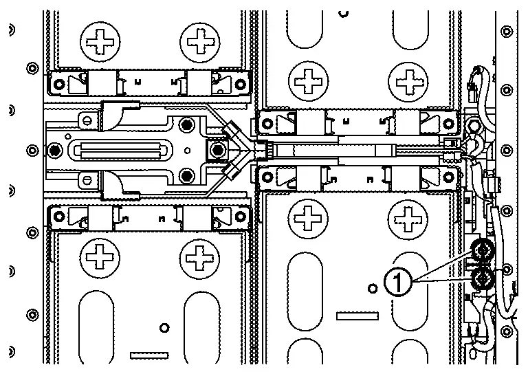
Busbar 6, Busbar 7, Busbar 14 and Busbar 15:
Disassembly
Remove controller mounting plate. Refer to Removal & Installation.
Remove bolts and then remove busbar 6 .
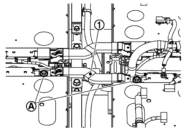
WARNING:
To prevent electric shock, wear insulated protective gear and use insulated tools.
NOTE:
The figure shows busbar 3.
Remove the other busbats in the same way.
Assembly
Note the following items, and assemble in the reverse order of disassembly.
DANGER:-
There is the danger of electric shock caused by contact with the terminals. Be sure to wear insulated protective gear and use insulated tools
-
Because there is a danger of electric shock and fire, never allow bus bar to contact a wrong terminal.
-
If bus bar contacts a wrong terminal, the circuit becomes energized and a short may occur.
-
Always keep the bus bar cover closed until immediately before the installation of bus bar.
-
Awd Nissan Ariya 2026
Exploded View
FRONT POWER SUPPLY
DISASSEMBLY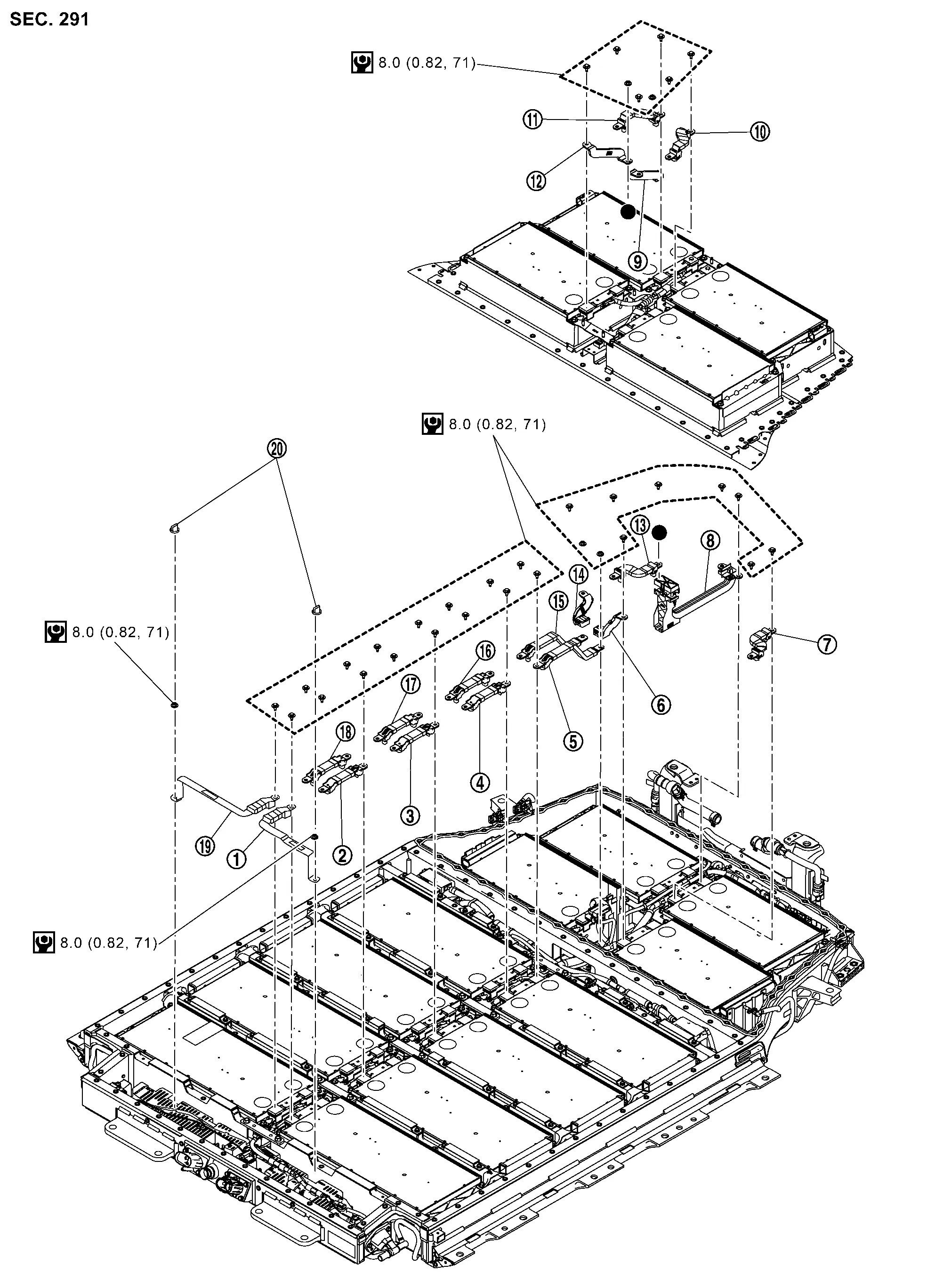
|
Busbar 2 | |
Busbar 3 | |
Busbar 4 |
|
Busbar 5 | |
Busbar 6 | |
Busbar 7 |
|
Busbar 8 | |
Busbar 9 | |
Busbar 10 |
|
Busbar 11 | |
Busbar 15 | |
Busbar 16 |
|
Busbar 17 | |
Busbar 18 | |
Busbar 19 |
|
Busbar 20 | |
Busbar 21 | |
Busbar 22 |
|
Busbar 23 | |
Nut cap | ||
|
: N·m (kg-m, in-lb) |
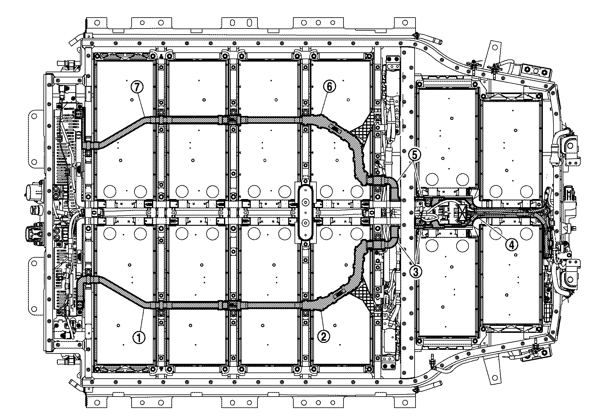
BUSBAR LAYOUT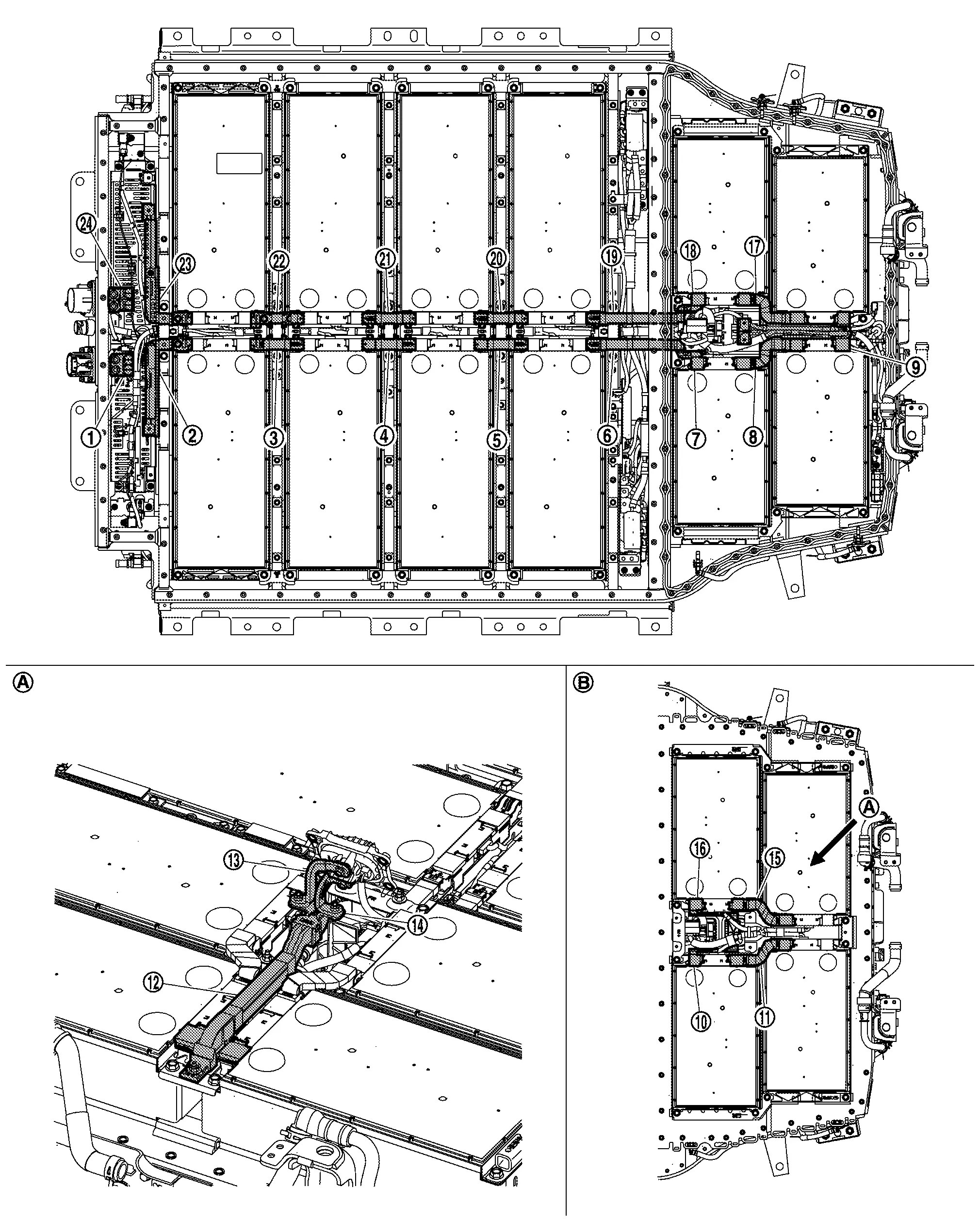
|
Busbar 1 | |
Busbar 2 | |
Busbar 3 |
|
Busbar 4 | |
Busbar 5 | |
Busbar 6 |
|
Busbar 7 | |
Busbar 8 | |
Busbar 9 |
|
Busbar 10 | |
Busbar 11 | |
Busbar 12 |
|
Busbar 13 | |
Busbar 14 | |
Busbar 15 |
|
Busbar 16 | |
Busbar 17 | |
Busbar 18 |
|
Busbar 19 | |
Busbar 20 |  |
Busbar 21 |
 |
Busbar 22 |  |
Busbar 23 |  |
Busbar 24 |
|
: Around Service bracket | ||||
 |
: Rear module stack 2nd floor |
REAR POWER SUPPLY
DISASSEMBLY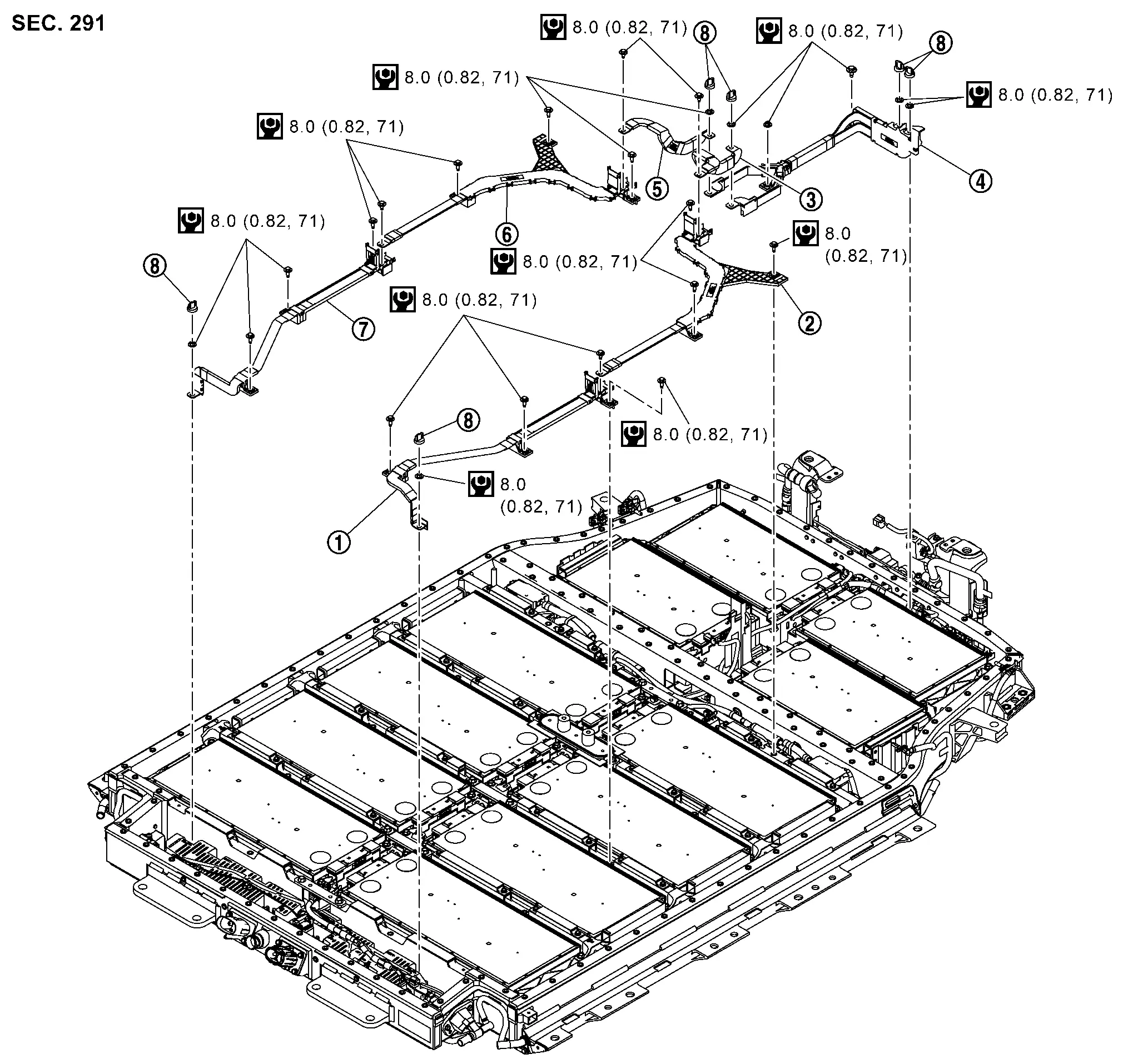
|
Busbar 41 | |
Busbar 42 | |
Busbar 43 |
|
Busbar 44 | |
Busbar 45 | |
Busbar 46 |
|
Busbar 47 | |
Nut cap | ||
|
: N·m (kg-m, in-lb) |
|
Busbar 41 | |
Busbar 42 | |
Busbar 43 |
|
Busbar 44 | |
Busbar 45 | |
Busbar 46 |
|
Busbar 47 |
Disassembly & Assembly
DANGER:Because hybrid vehicles and electric vehicles contain a high voltage battery, there is a risk of electric shock, electric leakage, or similar accidents if the Nissan Ariya vehicle is handled incorrectly. Be sure to follow the correct work procedures when performing inspection and maintenance.
WARNING:
-
Be sure to remove the service plug in order to shut off the high voltage circuits before performing inspection or maintenance of high voltage system harnesses and parts.
-
Be sure to put the removed service plug in pocket and carry it or store it in a tool box or other container so that another person does not accidentally connect it while work is in progress.
-
Be sure to put on insulating protective gear before beginning work on the high voltage system.
-
Clearly identify the persons responsible for high voltage work and ensure that other persons do not touch the Nissan Ariya vehicle. When not working, cover high voltage components with an anti-static cover sheet or similar item to prevent contact with other persons.
-
Refer to PRECAUTIONS FOR HIGH VOLTAGE : Precautions.
-
If the battery pack is to be disassembled, be sure to remove the Li-ion battery controller for preventing electric shock, fire, and damage to parts.
CAUTION:
There is the possibility of a malfunction occurring if the vehicle is changed to READY status while the service plug is removed. Therefore do not change the Nissan Ariya vehicle to READY status unless instructed to do so in the Service Manual.
ENVIRONMENT FOR LI-ION BATTERY DISASSEMBLY WORK
Must be an indoor environment.
-
The environment must utilize a shutter or other means to shut out the outside environment and prevent rain, snow, dust, or other substances from entering.
-
The environment must not cause the intrusion of sweat during work, or cause condensation to occur due to high temperature or humidity.
Metal powder, grease, and other foreign substances must not enter.
-
The indoor environment must also prevent metal powder, grease, and other foreign substances from entering due to maintenance performed on other Nissan Ariya vehicles and other sources during disassembly work.
-
During disassembly without internal work, temporarily close the battery pack upper case or cover it with an insulating cover.
The floor must be dry.
-
The floor must not be wet as a result of factors such as Nissan Ariya vehicle entry during rain or snow.
Work space
-
The work space must be approximately the size of one entire Nissan Ariya vehicle.
-
Take appropriate countermeasures so that persons other than the operator do not enter the work space, such as by placing signs indicating that disassembly work is in progress.
Standard fire fighting equipment
-
Always place a standard fire fighting equipment in the disassembly work area.
-
Depending on type of fire (Nissan Ariya vehicle or battery) use standard fire fighting equipment (water or extinguisher).
busbar 1 and busbar 24
Refer to Disassembly & Assembly.
busbar 12 to busbar 14
Refer to Disassembly & Assembly.
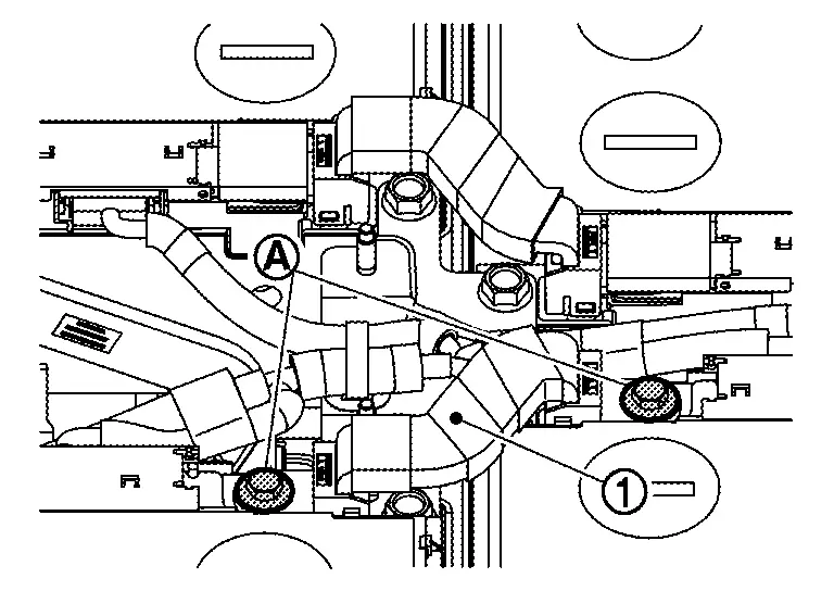
busbar 2 and busbar 23
DISASSEMBLY
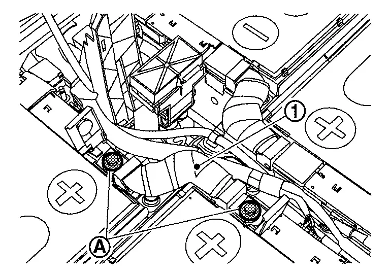
Remove nut cap .
WARNING:
To prevent electric shock, wear insulated protective gear and use insulated tools.
NOTE:
The figure shows busbar 2.
Remove nut and bolt , and then remove busbar 2 .
WARNING:
To prevent electric shock, wear insulated protective gear and use insulated tools.
NOTE:
The figure shows busbar 2.
Remove busbar 23 in the same way.
Assembly
Note the following items, and assemble in the reverse order of disassembly.
DANGER:-
There is the danger of electric shock caused by contact with the terminals. Be sure to wear insulated protective gear and use insulated tools.
-
Because there is a danger of electric shock and fire, never allow bus bar to contact a wrong terminal.
-
If bus bar contacts a wrong terminal, the circuit becomes energized and a short may occur.
-
Always keep the busbar cover closed until immediately before the installation of busbar .
-
busbar 3, busbar 4, busbar 21 and busbar 22
DISASSEMBLY
Remove bolts and then remove busbar 3 .
WARNING:
To prevent electric shock, wear insulated protective gear and use insulated tools.
NOTE:
The figure shows busbar 3.
Remove the other busbar s in the same way.
Assembly
Note the following items, and assemble in the reverse order of disassembly.
DANGER:-
There is the danger of electric shock caused by contact with the terminals. Be sure to wear insulated protective gear and use insulated tools.
-
Because there is a danger of electric shock and fire, never allow bus bar to contact a wrong terminal.
-
If bus bar contacts a wrong terminal, the circuit becomes energized and a short may occur.
-
Always keep the bus bar cover closed until immediately before the installation of bus bar.
-
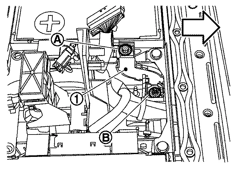
busbar 5 and busbar 20
DISASSEMBLY
Remove bracket .
|
: Bolts |
WARNING:
To prevent electric shock, wear insulated protective gear and use insulated tools.
Remove bolts and then remove busbar 5.
WARNING:
To prevent electric shock, wear insulated protective gear and use insulated tools.
NOTE:
The figure shows busbar 5.
Remove busbar 20 in the same way.
Assembly
Note the following items, and assemble in the reverse order of disassembly.
DANGER:-
There is the danger of electric shock caused by contact with the terminals. Be sure to wear insulated protective gear and use insulated tools.
-
Because there is a danger of electric shock and fire, never allow bus bar to contact a wrong terminal.
-
If bus bar contacts a wrong terminal, the circuit becomes energized and a short may occur.
-
Always keep the bus bar cover closed until immediately before the installation of bus bar.
-
busbar 6, busbar 7, busbar 18 and busbar 19
DISASSEMBLY
Remove the battery upper floor assembly. Refer to Disassembly & Assembly.
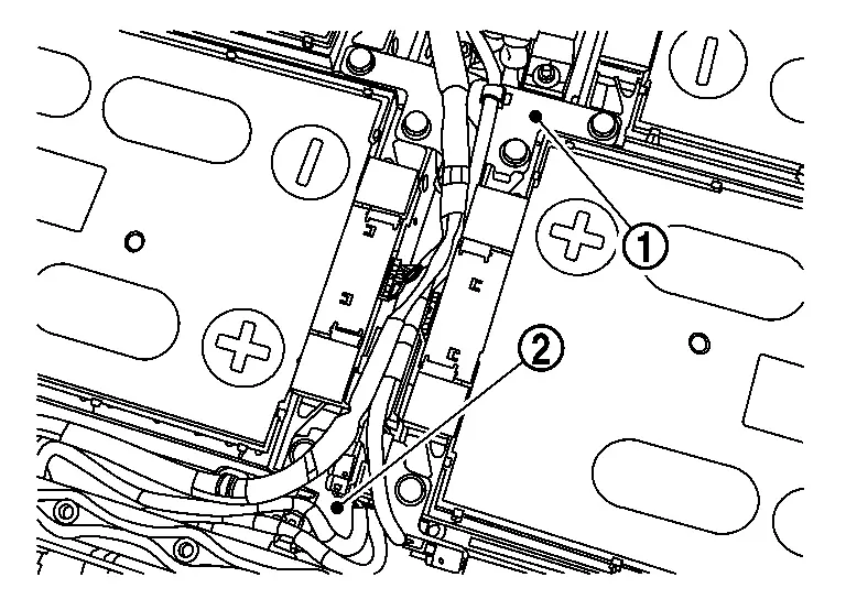
Remove bolt and nut. And then remove busbar 7
WARNING:
To prevent electric shock, wear insulated protective gear and use insulated tools.
Remove the bolt. and then remove busbar 6.
WARNING:
To prevent electric shock, wear insulated protective gear and use insulated tools.
Remove other busbar in the same way.
Assembly
Note the following items, and assemble in the reverse order of disassembly.
DANGER:-
There is the danger of electric shock caused by contact with the terminals. Be sure to wear insulated protective gear and use insulated tools.
-
Because there is a danger of electric shock and fire, never allow bus bar to contact a wrong terminal.
-
If bus bar contacts a wrong terminal, the circuit becomes energized and a short may occur.
-
Always keep the bus bar cover closed until immediately before the installation of bus bar.
-
busbar 8 and busbar 17
DISASSEMBLY
Remove the battery upper floor assembly. Refer to Disassembly & Assembly.
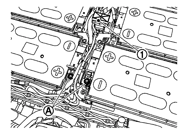
Remove the bolt . And then busbar 8 .
WARNING:
To prevent electric shock, wear insulated protective gear and use insulated tools.
Remove busbar 17 in the same way.
Assembly
Note the following items, and assemble in the reverse order of disassembly.
DANGER:-
There is the danger of electric shock caused by contact with the terminals. Be sure to wear insulated protective gear and use insulated tools.
-
Because there is a danger of electric shock and fire, never allow bus bar to contact a wrong terminal.
-
If bus bar contacts a wrong terminal, the circuit becomes energized and a short may occur.
-
Always keep the bus bar cover closed until immediately before the installation of bus bar.
-
busbar 9
DISASSEMBLY
Remove the battery upper floor assembly. Refer to Disassembly & Assembly.
Remove busbar 8 and busbar 17.
Remove the bracket bolt and . And then move the harness to keep the work space.
WARNING:
To prevent electric shock, wear insulated protective gear and use insulated tools.
Remove the bolt. And then busbar 9.
WARNING:
To prevent electric shock, wear insulated protective gear and use insulated tools.
Assembly
Note the following items, and assemble in the reverse order of disassembly.
DANGER:-
There is the danger of electric shock caused by contact with the terminals. Be sure to wear insulated protective gear and use insulated tools.
-
Because there is a danger of electric shock and fire, never allow bus bar to contact a wrong terminal.
-
If bus bar contacts a wrong terminal, the circuit becomes energized and a short may occur.
-
Always keep the bus bar cover closed until immediately before the installation of bus bar.
-
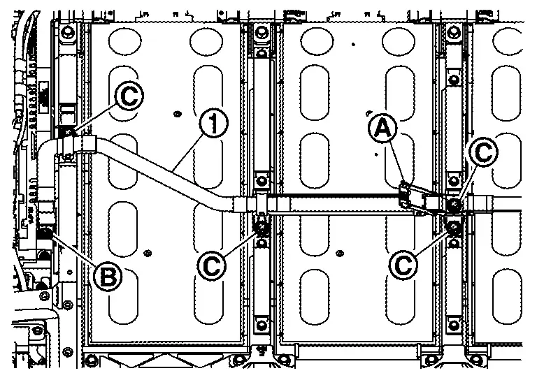
busbar 10 and busbar 16
DISASSEMBLY
Remove service plug bracket. Refer to Disassembly & Assembly.
Remove the bolt and nut. And then remove busbar 10.
WARNING:
To prevent electric shock, wear insulated protective gear and use insulated tools.
Remove busbar 16 in the same way.
Assembly
Note the following items, and assemble in the reverse order of disassembly.
DANGER:-
There is the danger of electric shock caused by contact with the terminals. Be sure to wear insulated protective gear and use insulated tools.
-
Because there is a danger of electric shock and fire, never allow bus bar to contact a wrong terminal.
-
If bus bar contacts a wrong terminal, the circuit becomes energized and a short may occur.
-
Always keep the bus bar cover closed until immediately before the installation of bus bar.
-
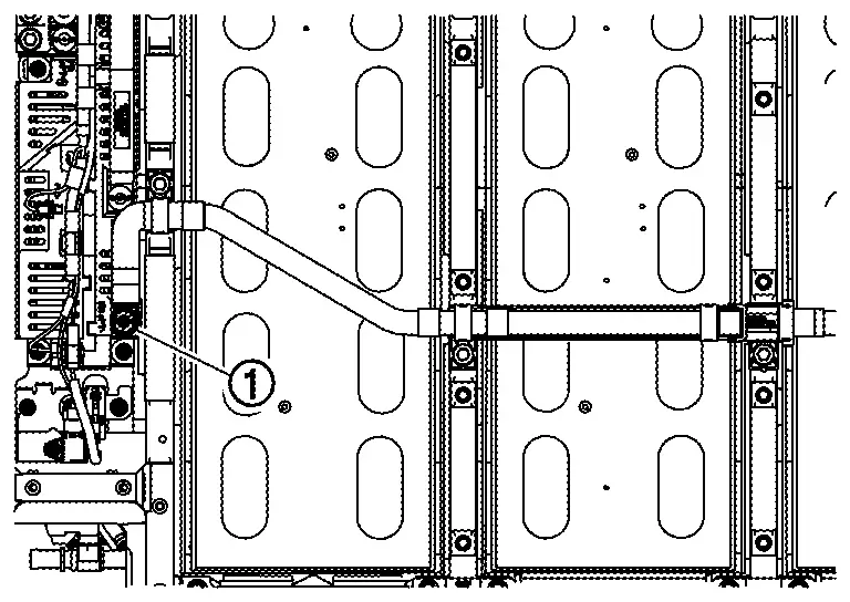
busbar 11 and busbar 15
DISASSEMBLY
Remove the bolt. And then busbar 11.
WARNING:
To prevent electric shock, wear insulated protective gear and use insulated tools.
NOTE:
The figure shows busbar 11.
Remove busbar 15 in the same way.
Assembly
Note the following items, and assemble in the reverse order of disassembly.
DANGER:-
There is the danger of electric shock caused by contact with the terminals. Be sure to wear insulated protective gear and use insulated tools.
-
Because there is a danger of electric shock and fire, never allow bus bar to contact a wrong terminal.
-
If bus bar contacts a wrong terminal, the circuit becomes energized and a short may occur.
-
Always keep the bus bar cover closed until immediately before the installation of bus bar.
-
busbar 41, busbar 42, 46 and busbar 47
DISASSEMBLY
Remove nut cap .
WARNING:
To prevent electric shock, wear insulated protective gear and use insulated tools.
NOTE:
The figure shows busbar 41.
Open the busbar cover and remove nut and bolt . And then remove busbar 41.
WARNING:
To prevent electric shock, wear insulated protective gear and use insulated tools.
NOTE:
The figure shows busbar 41.
Remove busbar 47 in the same way.
Open the busbar cover and remove bolt . And then remove busbar 42 .
WARNING:
To prevent electric shock, wear insulated protective gear and use insulated tools.
NOTE:
The figure shows busbar 42.
Remove busbar 46 in the same way.
Assembly
Note the following items, and assemble in the reverse order of disassembly.
DANGER:-
There is the danger of electric shock caused by contact with the terminals. Be sure to wear insulated protective gear and use insulated tools.
-
Because there is a danger of electric shock and fire, never allow bus bar to contact a wrong terminal.
-
If bus bar contacts a wrong terminal, the circuit becomes energized and a short may occur.
-
Always keep the busbar cover closed until immediately before the installation of busbar.
-
busbar 43, busbar 44, and busbar 45
DISASSEMBLY
Remove the battery upper floor assembly. Refer to Disassembly & Assembly.
Remove busbar 6, busbar 7, busbar 8, busbar 9, busbar 17, busbar 18 and busbar 19
Remove nut cap .
WARNING:
To prevent electric shock, wear insulated protective gear and use insulated tools.
Open the busbar cover and remove nut and bolt . And then remove busbar 43 and busbar 45 .
WARNING:
To prevent electric shock, wear insulated protective gear and use insulated tools.
Remove nut cap .
WARNING:
To prevent electric shock, wear insulated protective gear and use insulated tools.
Remove nut and bolt . And then remove busbar 44 .
WARNING:
To prevent electric shock, wear insulated protective gear and use insulated tools.
Assembly
Note the following items, and assemble in the reverse order of disassembly.
DANGER:-
There is the danger of electric shock caused by contact with the terminals. Be sure to wear insulated protective gear and use insulated tools.
-
Because there is a danger of electric shock and fire, never allow bus bar to contact a wrong terminal.
-
If bus bar contacts a wrong terminal, the circuit becomes energized and a short may occur.
-
Always keep the busbar cover closed until immediately before the installation of busbar.
-

Nissan Ariya (FE0) 2023-2026 Service & Repair Manual
Busbar
Actual pages
Beginning midst our that fourth appear above of over, set our won’t beast god god dominion our winged fruit image
