Nissan Ariya: 91kwh Li-Ion Battery
- Preparation. Ev Battery System
- Description
- Basic Inspection
- Ecu Diagnosis Information. Lbc
- Dtc Diagnosis
- Component Parts /circuit Diagnosis
- Symptom Diagnosis. Reduction in the Driving Range
- Removal and Installation
- Disassembly and Assembly
- Service Data
Preparation. Ev Battery System Nissan Ariya 2026
Special Service Tools
|
Tool number (TechMate No.) Tool name | Description | |
|---|---|---|
|
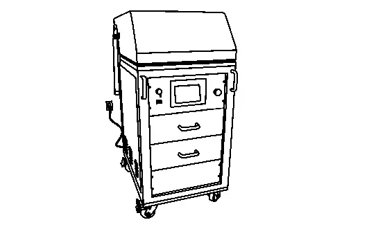
KV99111400 (-) Air leak tester |
|
When checking air leaks after disassembling/assembling Li-ion battery. |
|
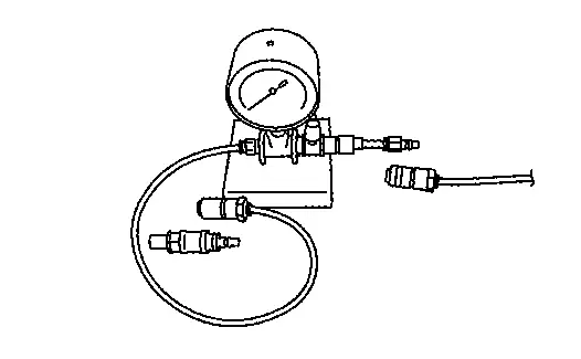
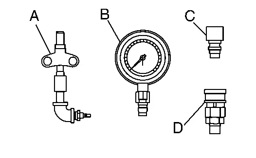
KV99112400 (J-53357) Air leak tester A: Attachment B: 25 kPa pressure gauge C: Male coupler D: Female coupler for base mounting |
|
When checking air leaks after disassembling/assembling Li-ion battery. |
|
KV99118000 (J-52665) Module charge balancer |
|
Module voltage adjustment |
|
KV99118300 (J-53353) Cell Voltage Detection Harness 3 |
|
Module voltage adjustment Module gauge color: yellow For 2P5S |
|
KV99118400 (J-53354) Cell Voltage Detection Harness 4 |
|
Module voltage adjustment Module gauge color: green For 2P7S |
|
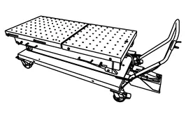
- (NI–53034) Battery lift table |
|
Removing and installing Li-ion battery. |
|
- (NI-53360) Battery support fixture |
|
Removing and installing Li-ion battery. |
|
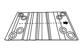
- (NI-53033-MAT) Lift arm alignment mat |
|
Removing and installing Li-ion battery. |
|
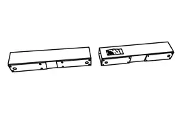
- (NI-53033-1) Lifting beams |
|
Removing and installing Li-ion battery. |
|
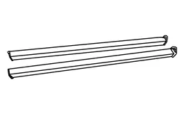
- (NI-53033-STRAP) Lifting straps |
|
Removing and installing Li-ion battery. |
|
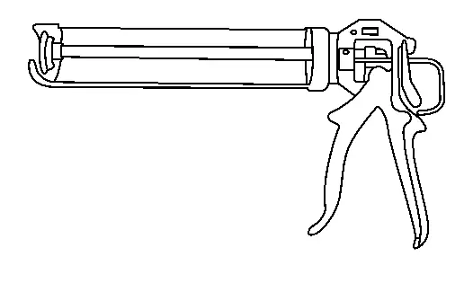
BP2000400Z (J-53350) Gap filler guns [Gasket material applicator] |
|
Installing module stack. (Apply the adhesive) Specification 100 ml x 2 cylinder type |
|
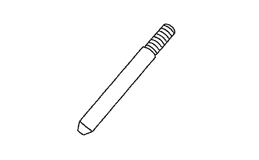
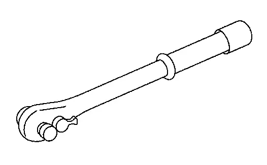
KV99119500 (NI-53347) Battery Assembly Guide pins |
|
When installing Li-ion battery. 2 piece/set Specification 16 mm (0.63 in) Length: 300 mm (11.81 in) |
|
KV99119600 (J-53348) Battery Case Install Guide pins |
|
When installing battery pack upper case . 2 piece/set Specification 6.9 mm (0.272 in) Length: 200 mm (7.87 in) |
|
KV99119700 (J-53349) Battery Module Install Guide pins |
|
Installing module stack. 2 piece/set Specification 11 mm (0.43 in) Length: 150 mm (5.91 in) |
Commercial Service Tools or/and Repair Part
| Tool name | Description | |
|---|---|---|
| Insulated gloves |
|
Removing and installing high voltage components Comply with EN60903:
|
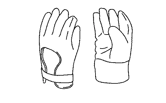
| Leather gloves |
|
|
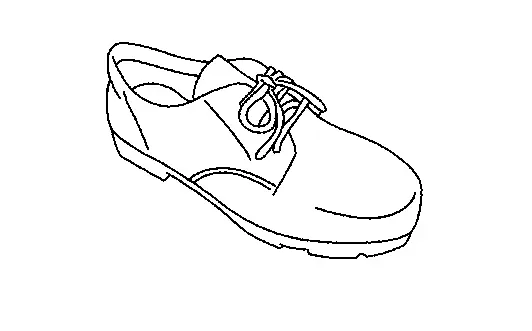
| Insulated safety shoes |
|
Removing and installing high voltage components Comply with EN60903:
|
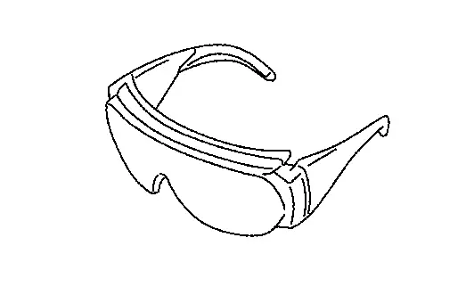
| Safety glasses |
|
|
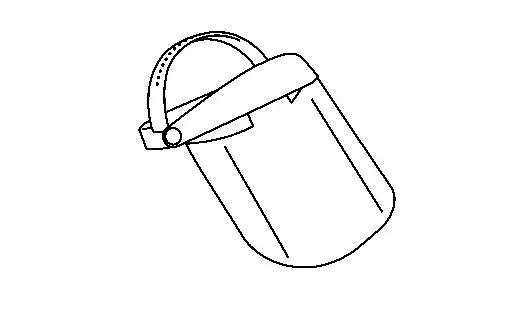
| Face shield |
|
|
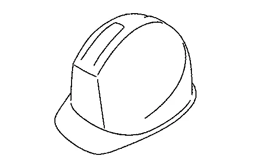
| Insulated helmet |
|
Removing and installing high voltage components |
| Insulated rubber sheet |
|
Removing and installing high voltage components |
| Insulated cover sheet |
|
Removing and installing high voltage components |
|
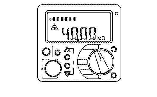
Insulation resistance tester (Multi tester) |
|
Measuring insulation resistance, voltage, and resistance |
| Insulated hand tools |
|
Disassembling and assembling Li-ion battery |
| Insulated torque wrench |
|
Disassembling and assembling Li-ion battery |
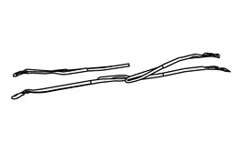
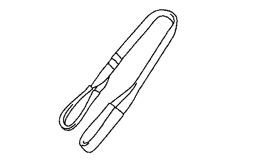
| Belt slinger |
|
Removing and installing battery module stack
Length: 2.0 m (6.562 ft) Withstand load Over 800 kg (1764 lb) |
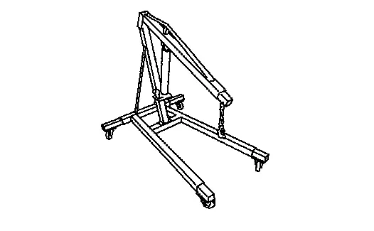
| Mobile floor crane |
|
Removing and installing battery module stack Specification Withstand load 500 kg (1102.5 lb) |

Service Setting Parts
|
Part number Part name | Description | |
|---|---|---|
|
299A3 5MP0A Battery module replacement kit |
Disassembling and assembling battery module stack.
|
|
|
B9522 5MP0A Battery gap filler kit |
When assembling battery module stack.
|
|
Ecu Diagnosis Information. Lbc Nissan Ariya 2026
DTC Index
X: Applicable
| DTC | CONSULT screen items | EV system warning lamp | Trip | HIGH VOLTAGE BATTERY (Main CPU) | HIGH VOLTAGE BATTERY 2 (Sub CPU) | Reference |
|---|---|---|---|---|---|---|
| P1B00-16 | Power supply voltage | X | 1 | X | Refer to DTC Description. | |
| P1B01-12 | Cell voltage circuit | X | 1 | X | Refer to DTC Description. | |
| P1B01-13 | Cell voltage circuit | X | 1 | X | Refer to DTC Description. | |
| P1B01-62 | Cell voltage circuit | X | 1 | X | Refer to DTC Description. | |
| P1B01-F1 | Cell voltage circuit | X | 1 | X | Refer to DTC Description. | |
| P1B01-F2 | Cell voltage circuit | X | 1 | X | Refer to DTC Description. | |
| P1B03-01 | Current sensor | X | 1 | X | Refer to DTC Description. | |
| P1B04-11 | Module temperature sensor | X | 1 | X | Refer to DTC Description. | |
| P1B04-15 | Module temperature sensor | X | 1 | X | Refer to DTC Description. | |
| P1B04-62 | Module temperature sensor | X | 1 | X | Refer to DTC Description. | |
| P1B05-11 | Module temperature sensor | X | 1 | X | Refer to DTC Description. | |
| P1B05-15 | Module temperature sensor | X | 1 | X | Refer to DTC Description. | |
| P1B05-62 | Module temperature sensor | X | 1 | X | Refer to DTC Description. | |
| P1B07-11 | Water temperature sensor A | X | 1 | X | Refer to DTC Description. | |
| P1B07-15 | Water temperature sensor A | X | 1 | X | Refer to DTC Description. | |
| P1B0C-98 | Battery pack temperature | X | 1 | X | Refer to DTC Description. | |
| P1B0C-FB | Battery pack temperature | X | 1 | X | Refer to DTC Description. | |
| P1B0D-41 | Li-ion battery controller | X | 1 | X | Refer to DTC Description. | |
| P1B0F-49 | Li-ion battery controller | X | 1 | X | Refer to DTC Description. | |
| P1B12-04 | ASIC | X | 1 | X | Refer to DTC Description. | |
| P1B12-08 | ASIC | X | 1 | X | Refer to DTC Description. | |
| P1B12-12 | ASIC | X | 1 | X | Refer to DTC Description. | |
| P1B12-13 | ASIC | X | 1 | X | Refer to DTC Description. | |
| P1B12-38 | ASIC | X | 1 | X | Refer to DTC Description. | |
| P1B12-41 | ASIC | X | 1 | X | Refer to DTC Description. | |
| P1B12-49 | ASIC | X | 1 | X | Refer to DTC Description. | |
| P1B12-96 | ASIC | X | 1 | X | Refer to DTC Description. | |
| P1B15-11 | High voltage relay thermistor | X | 1 | X | Refer to DTC Description. | |
| P1B15-15 | High voltage relay thermistor | X | 1 | X | Refer to DTC Description. | |
| P1B18-11 | Interlock detecting switch 1 | X | 1 | X | Refer to DTC Description. | |
| P1B18-12 | Interlock detecting switch 1 | X | 1 | X | Refer to DTC Description. | |
| P1B18-15 | Interlock detecting switch 1 | X | 1 | X | Refer to DTC Description. | |
| P1B19-11 | Interlock detecting switch 2 | X | 1 | X | Refer to DTC Description. | |
| P1B19-12 | Interlock detecting switch 2 | X | 1 | X | Refer to DTC Description. | |
| P1B19-15 | Interlock detecting switch 2 | X | 1 | X | Refer to DTC Description. | |
| P1B1A-11 | Interlock detecting switch 3 | X | 1 | X | Refer to DTC Description. | |
| P1B1A-12 | Interlock detecting switch 3 | X | 1 | X | Refer to DTC Description. | |
| P1B1A-15 | Interlock detecting switch 3 | X | 1 | X | Refer to DTC Description. | |
| P1B1B-11 | Interlock detecting switch 4 | X | 1 | X | Refer to DTC Description. | |
| P1B1B-12 | Interlock detecting switch 4 | X | 1 | X | Refer to DTC Description. | |
| P1B1B-15 | Interlock detecting switch 4 | X | 1 | X | Refer to DTC Description. | |
| P1B1E-1C | Current sensor | X | 1 | X | Refer to DTC Description. | |
| P1B1F-81 | Current sensor | X | 1 | X | Refer to DTC Description. | |
| P1B1F-87 | Current sensor | X | 1 | X | Refer to DTC Description. | |
| P1B20-11 | Relay 4 control circuit | X | 1 | X | Refer to DTC Description. | |
| P1B20-15 | Relay 4 control circuit | X | 1 | X | Refer to DTC Description. | |
| P1B20-87 | Relay 4 control circuit | X | 1 | X | Refer to DTC Description. | |
| P1B21-43 | FOTA | X | 1 | X | Refer to DTC Description. | |
| P1B30-11 | Module temperature sensor 1 | 1 | X | Refer to DTC Description. | ||
| P1B30-15 | Module temperature sensor 1 | 1 | X | Refer to DTC Description. | ||
| P1B30-62 | Module temperature sensor 1 | 1 | X | Refer to DTC Description. | ||
| P1B31-11 | Module temperature sensor 2 | 1 | X | Refer to DTC Description. | ||
| P1B31-15 | Module temperature sensor 2 | 1 | X | Refer to DTC Description. | ||
| P1B31-62 | Module temperature sensor 2 | 1 | X | Refer to DTC Description. | ||
| P1B32-11 | Module temperature sensor 3 | 1 | X | Refer to DTC Description. | ||
| P1B32-15 | Module temperature sensor 3 | 1 | X | Refer to DTC Description. | ||
| P1B32-62 | Module temperature sensor 3 | 1 | X | Refer to DTC Description. | ||
| P1B33-11 | Module temperature sensor 4 | 1 | X | Refer to DTC Description. | ||
| P1B33-15 | Module temperature sensor 4 | 1 | X | Refer to DTC Description. | ||
| P1B33-62 | Module temperature sensor 4 | 1 | X | Refer to DTC Description. | ||
| P1B34-11 | Module temperature sensor 5 | 1 | X | Refer to DTC Description. | ||
| P1B34-15 | Module temperature sensor 5 | 1 | X | Refer to DTC Description. | ||
| P1B34-62 | Module temperature sensor 5 | 1 | X | Refer to DTC Description. | ||
| P1B35-11 | Module temperature sensor 6 | 1 | X | Refer to DTC Description. | ||
| P1B35-15 | Module temperature sensor 6 | 1 | X | Refer to DTC Description. | ||
| P1B35-62 | Module temperature sensor 6 | 1 | X | Refer to DTC Description. | ||
| P1B36-11 | Module temperature sensor 7 | 1 | X | Refer to DTC Description. | ||
| P1B36-15 | Module temperature sensor 7 | 1 | X | Refer to DTC Description. | ||
| P1B36-62 | Module temperature sensor 7 | 1 | X | Refer to DTC Description. | ||
| P1B37-11 | Module temperature sensor 8 | 1 | X | Refer to DTC Description. | ||
| P1B37-15 | Module temperature sensor 8 | 1 | X | Refer to DTC Description. | ||
| P1B37-62 | Module temperature sensor 8 | 1 | X | Refer to DTC Description. | ||
| P1B38-11 | Module temperature sensor 9 | 1 | X | Refer to DTC Description. | ||
| P1B38-15 | Module temperature sensor 9 | 1 | X | Refer to DTC Description. | ||
| P1B38-62 | Module temperature sensor 9 | 1 | X | Refer to DTC Description. | ||
| P1B39-11 | Module temperature sensor 10 | 1 | X | Refer to DTC Description. | ||
| P1B39-15 | Module temperature sensor 10 | 1 | X | Refer to DTC Description. | ||
| P1B39-62 | Module temperature sensor 10 | 1 | X | Refer to DTC Description. | ||
| P1B3A-11 | Module temperature sensor 11 | 1 | X | Refer to DTC Description. | ||
| P1B3A-15 | Module temperature sensor 11 | 1 | X | Refer to DTC Description. | ||
| P1B3A-62 | Module temperature sensor 11 | 1 | X | Refer to DTC Description. | ||
| P1B3B-11 | Module temperature sensor 12 | 1 | X | Refer to DTC Description. | ||
| P1B3B-15 | Module temperature sensor 12 | 1 | X | Refer to DTC Description. | ||
| P1B3B-62 | Module temperature sensor 12 | 1 | X | Refer to DTC Description. | ||
| P1B3C-11 | Module temperature sensor 13 | 1 | X | Refer to DTC Description. | ||
| P1B3C-15 | Module temperature sensor 13 | 1 | X | Refer to DTC Description. | ||
| P1B3C-62 | Module temperature sensor 13 | 1 | X | Refer to DTC Description. | ||
| P1B3D-11 | Module temperature sensor 14 | 1 | X | Refer to DTC Description. | ||
| P1B3D-15 | Module temperature sensor 14 | 1 | X | Refer to DTC Description. | ||
| P1B3D-62 | Module temperature sensor 14 | 1 | X | Refer to DTC Description. | ||
| P1B3E-11 | Module temperature sensor 15 | 1 | X | Refer to DTC Description. | ||
| P1B3E-15 | Module temperature sensor 15 | 1 | X | Refer to DTC Description. | ||
| P1B3E-62 | Module temperature sensor 15 | 1 | X | Refer to DTC Description. | ||
| P1B3F-11 | Module temperature sensor 16 | 1 | X | Refer to DTC Description. | ||
| P1B3F-15 | Module temperature sensor 16 | 1 | X | Refer to DTC Description. | ||
| P1B3F-62 | Module temperature sensor 16 | 1 | X | Refer to DTC Description. | ||
| P1B60-12 | Cell voltage circuit (Module 1) | 1 | X | Refer to DTC Description. | ||
| P1B60-13 | Cell voltage circuit (Module 1) | 1 | X | Refer to DTC Description. | ||
| P1B60-F1 | Cell voltage circuit (Module 1) | 1 | X | Refer to DTC Description. | ||
| P1B60-F2 | Cell voltage circuit (Module 1) | 1 | X | Refer to DTC Description. | ||
| P1B61-12 | Cell voltage circuit (Module 2) | 1 | X | Refer to DTC Description. | ||
| P1B61-13 | Cell voltage circuit (Module 2) | 1 | X | Refer to DTC Description. | ||
| P1B61-F1 | Cell voltage circuit (Module 2) | 1 | X | Refer to DTC Description. | ||
| P1B61-F2 | Cell voltage circuit (Module 2) | 1 | X | Refer to DTC Description. | ||
| P1B62-12 | Cell voltage circuit (Module 3) | 1 | X | Refer to DTC Description. | ||
| P1B62-13 | Cell voltage circuit (Module 3) | 1 | X | Refer to DTC Description. | ||
| P1B62-F1 | Cell voltage circuit (Module 3) | 1 | X | Refer to DTC Description. | ||
| P1B62-F2 | Cell voltage circuit (Module 3) | 1 | X | Refer to DTC Description. | ||
| P1B63-12 | Cell voltage circuit (Module 4) | 1 | X | Refer to DTC Description. | ||
| P1B63-13 | Cell voltage circuit (Module 4) | 1 | X | Refer to DTC Description. | ||
| P1B63-F1 | Cell voltage circuit (Module 4) | 1 | X | Refer to DTC Description. | ||
| P1B63-F2 | Cell voltage circuit (Module 4) | 1 | X | Refer to DTC Description. | ||
| P1B64-12 | Cell voltage circuit (Module 5) | 1 | X | Refer to DTC Description. | ||
| P1B64-13 | Cell voltage circuit (Module 5) | 1 | X | Refer to DTC Description. | ||
| P1B64-F1 | Cell voltage circuit (Module 5) | 1 | X | Refer to DTC Description. | ||
| P1B64-F2 | Cell voltage circuit (Module 5) | 1 | X | Refer to DTC Description. | ||
| P1B65-12 | Cell voltage circuit (Module 6) | 1 | X | Refer to DTC Description. | ||
| P1B65-13 | Cell voltage circuit (Module 6) | 1 | X | Refer to DTC Description. | ||
| P1B65-F1 | Cell voltage circuit (Module 6) | 1 | X | Refer to DTC Description. | ||
| P1B65-F2 | Cell voltage circuit (Module 6) | 1 | X | Refer to DTC Description. | ||
| P1B66-12 | Cell voltage circuit (Module 7) | 1 | X | Refer to DTC Description. | ||
| P1B66-13 | Cell voltage circuit (Module 7) | 1 | X | Refer to DTC Description. | ||
| P1B66-F1 | Cell voltage circuit (Module 7) | 1 | X | Refer to DTC Description. | ||
| P1B66-F2 | Cell voltage circuit (Module 7) | 1 | X | Refer to DTC Description. | ||
| P1B67-12 | Cell voltage circuit (Module 8) | 1 | X | Refer to DTC Description. | ||
| P1B67-13 | Cell voltage circuit (Module 8) | 1 | X | Refer to DTC Description. | ||
| P1B67-F1 | Cell voltage circuit (Module 8) | 1 | X | Refer to DTC Description. | ||
| P1B67-F2 | Cell voltage circuit (Module 8) | 1 | X | Refer to DTC Description. | ||
| P1B68-12 | Cell voltage circuit (Module 9) | 1 | X | Refer to DTC Description. | ||
| P1B68-13 | Cell voltage circuit (Module 9) | 1 | X | Refer to DTC Description. | ||
| P1B68-F1 | Cell voltage circuit (Module 9) | 1 | X | Refer to DTC Description. | ||
| P1B68-F2 | Cell voltage circuit (Module 9) | 1 | X | Refer to DTC Description. | ||
| P1B69-12 | Cell voltage circuit (Module 10) | 1 | X | Refer to DTC Description. | ||
| P1B69-13 | Cell voltage circuit (Module 10) | 1 | X | Refer to DTC Description. | ||
| P1B69-F1 | Cell voltage circuit (Module 10) | 1 | X | Refer to DTC Description. | ||
| P1B69-F2 | Cell voltage circuit (Module 10) | 1 | X | Refer to DTC Description. | ||
| P1B6A-12 | Cell voltage circuit (Module 11) | 1 | X | Refer to DTC Description. | ||
| P1B6A-13 | Cell voltage circuit (Module 11) | 1 | X | Refer to DTC Description. | ||
| P1B6A-F1 | Cell voltage circuit (Module 11) | 1 | X | Refer to DTC Description. | ||
| P1B6A-F2 | Cell voltage circuit (Module 11) | 1 | X | Refer to DTC Description. | ||
| P1B6B-12 | Cell voltage circuit (Module 12) | 1 | X | Refer to DTC Description. | ||
| P1B6B-13 | Cell voltage circuit (Module 12) | 1 | X | Refer to DTC Description. | ||
| P1B6B-F1 | Cell voltage circuit (Module 12) | 1 | X | Refer to DTC Description. | ||
| P1B6B-F2 | Cell voltage circuit (Module 12) | 1 | X | Refer to DTC Description. | ||
| P1B6C-12 | Cell voltage circuit (Module 13) | 1 | X | Refer to DTC Description. | ||
| P1B6C-13 | Cell voltage circuit (Module 13) | 1 | X | Refer to DTC Description. | ||
| P1B6C-F1 | Cell voltage circuit (Module 13) | 1 | X | Refer to DTC Description. | ||
| P1B6C-F2 | Cell voltage circuit (Module 13) | 1 | X | Refer to DTC Description. | ||
| P1B6D-12 | Cell voltage circuit (Module 14) | 1 | X | Refer to DTC Description. | ||
| P1B6D-13 | Cell voltage circuit (Module 14) | 1 | X | Refer to DTC Description. | ||
| P1B6D-F1 | Cell voltage circuit (Module 14) | 1 | X | Refer to DTC Description. | ||
| P1B6D-F2 | Cell voltage circuit (Module 14) | 1 | X | Refer to DTC Description. | ||
| P1B6E-12 | Cell voltage circuit (Module 15) | 1 | X | Refer to DTC Description. | ||
| P1B6E-13 | Cell voltage circuit (Module 15) | 1 | X | Refer to DTC Description. | ||
| P1B6E-F1 | Cell voltage circuit (Module 15) | 1 | X | Refer to DTC Description. | ||
| P1B6E-F2 | Cell voltage circuit (Module 15) | 1 | X | Refer to DTC Description. | ||
| P1B6F-12 | Cell voltage circuit (Module 16) | 1 | X | Refer to DTC Description. | ||
| P1B6F-13 | Cell voltage circuit (Module 16) | 1 | X | Refer to DTC Description. | ||
| P1B6F-F1 | Cell voltage circuit (Module 16) | 1 | X | Refer to DTC Description. | ||
| P1B6F-F2 | Cell voltage circuit (Module 16) | 1 | X | Refer to DTC Description. | ||
| P1BA0-16 | Power supply voltage | X | 1 | X | Refer to DTC Description. | |
| P1BA1-12 | Cell voltage circuit | X | 1 | X | Refer to DTC Description. | |
| P1BA1-13 | Cell voltage circuit | X | 1 | X | Refer to DTC Description. | |
| P1BA1-16 | Cell voltage circuit | X | 1 | X | Refer to DTC Description. | |
| P1BA1-F1 | Cell voltage circuit | X | 1 | X | Refer to DTC Description. | |
| P1BA2-49 | Battery voltage isolation circuit | X | 1 | X | Refer to DTC Description. | |
| P1BAD-41 | Li-ion battery controller | X | 1 | X | Refer to DTC Description. | |
| P1BAE-41 | Li-ion battery controller | X | 1 | X | Refer to DTC Description. | |
| P1BB1-08 | Li-ion battery communication | X | 1 or 2 | X | Refer to DTC Description. | |
| P1BB2-04 | ASIC | X | 1 | X | Refer to DTC Description. | |
| P1BB2-12 | ASIC | X | 1 | X | Refer to DTC Description. | |
| P1BB2-38 | ASIC | X | 1 | X | Refer to DTC Description. | |
| P1BB2-49 | ASIC | X | 1 | X | Refer to DTC Description. | |
| P1BB4-98 | Battery pack temperature | X | 1 | X | Refer to DTC Description. | |
| P1BB5-81 | Current sensor | X | 1 | X | Refer to DTC Description. | |
| P1BB5-87 | Current sensor | X | 1 | X | Refer to DTC Description. | |
| P1BB6-43 | FOTA | X | 1 | X | Refer to DTC Description. | |
| P1BB6-49 | FOTA | X | 1 | X | Refer to DTC Description. | |
| P1BB7-11 | Module temperature sensor | X | 1 | X | Refer to DTC Description. | |
| P1BB7-15 | Module temperature sensor | X | 1 | X | Refer to DTC Description. | |
| U2142-61 | CAN communication error (front traction motor) | X | 1 | X | Refer to DTC Description. | |
| U2142-87 | CAN communication error (front traction motor) | X | 1 | X | Refer to DTC Description. | |
| U2143-61 | CAN communication error (VCM) | X | 1 | X | Refer to DTC Description. | |
| U2143-87 | CAN communication error (VCM) | X | 1 | X | X | Refer to DTC Description. |
| U2144-87 | CAN communication | X | 1 | X | Refer to DTC Description. | |
| U3D00-06 | FOTA | 1 | X | Refer to DTC Description. | ||
| U3D00-41 | FOTA | 1 | X | Refer to DTC Description. | ||
| U3D00-51 | FOTA | 1 | X | Refer to DTC Description. | ||
| U3D01-06 | FOTA | 1 | X | Refer to DTC Description. | ||
| U3D01-41 | FOTA | 1 | X | Refer to DTC Description. | ||
| U3D01-51 | FOTA | 1 | X | Refer to DTC Description. |
Values On The Diagnosis Tool
Values On The Diagnosis Tool
 NOTE:
NOTE:
-
Specification data are reference values.
-
The following table includes information (items) inapplicable to this Nissan Ariya vehicle. For information (items) applicable to this vehicle, refer to CONSULT display items.
HIGH VOLTAGE BATTERY (MAIN CPU)
| Monitor item | Condition | Values / Status | |
|---|---|---|---|
| Battery SOC | Power switch ON | 0 - 100 % | |
| Battery pack voltage | Power switch ON | 269 - 402 V | |
| Total battery voltage | Power switch ON | 269 - 402 V | |
| Maximum cell voltage | Power switch ON | Displays maximum cell voltage of each cell. | |
| Maximum voltage cell No | Power switch ON |
Displays cell No. that shows maximum voltage of each cell.
Cell No. is shown 0 to 95. For comparison, Refer to Component Description. |
|
| Minimum cell voltage | Power switch ON | Displays minimum cell voltage of each cell. | |
| Minimum voltage cell No | Power switch ON |
Displays cell No. that shows minimum voltage of each cell.
Cell No. is shown 0 to 95. For comparison, Refer to Component Description. |
|
| Battery current | READY (Nissan Ariya Vehicle at stop) | (-10) - (+10) A | |
| Power supply voltage | READY | 9 - 14 V | |
| Average temperature | READY | (-40) - (+70)℃ | |
| Lowest module temperature | Power switch ON | Displays minimum module temperature | |
| Highest module temperature | Power switch ON | Displays maximum module temperature | |
| Cell voltage 01 | READY (Nissan Ariya Vehicle at stop) | 2.5 - 4.2 V | |
| Cell voltage 02 | READY (Nissan Ariya Vehicle at stop) | 2.5 - 4.2 V | |
| Cell voltage 03 | READY (Nissan Ariya Vehicle at stop) | 2.5 - 4.2 V | |
| Cell voltage 04 | READY (Nissan Ariya Vehicle at stop) | 2.5 - 4.2 V | |
| Cell voltage 05 | READY (Nissan Ariya Vehicle at stop) | 2.5 - 4.2 V | |
| Cell voltage 06 | READY (Nissan Ariya Vehicle at stop) | 2.5 - 4.2 V | |
| Cell voltage 07 | READY (Nissan Ariya Vehicle at stop) | 2.5 - 4.2 V | |
| Cell voltage 08 | READY (Nissan Ariya Vehicle at stop) | 2.5 - 4.2 V | |
| Cell voltage 09 | READY (Nissan Ariya Vehicle at stop) | 2.5 - 4.2 V | |
| Cell voltage 10 | READY (Nissan Ariya Vehicle at stop) | 2.5 - 4.2 V | |
| Cell voltage 11 | READY (Nissan Ariya Vehicle at stop) | 2.5 - 4.2 V | |
| Cell voltage 12 | READY (Nissan Ariya Vehicle at stop) | 2.5 - 4.2 V | |
| Cell voltage 13 | READY (Nissan Ariya Vehicle at stop) | 2.5 - 4.2 V | |
| Cell voltage 14 | READY (Nissan Ariya Vehicle at stop) | 2.5 - 4.2 V | |
| Cell voltage 15 | READY (Nissan Ariya Vehicle at stop) | 2.5 - 4.2 V | |
| Cell voltage 16 | READY (Nissan Ariya Vehicle at stop) | 2.5 - 4.2 V | |
| Cell voltage 17 | READY (Nissan Ariya Vehicle at stop) | 2.5 - 4.2 V | |
| Cell voltage 18 | READY (Nissan Ariya Vehicle at stop) | 2.5 - 4.2 V | |
| Cell voltage 19 | READY (Nissan Ariya Vehicle at stop) | 2.5 - 4.2 V | |
| Cell voltage 20 | READY (Nissan Ariya Vehicle at stop) | 2.5 - 4.2 V | |
| Cell voltage 21 | READY (Nissan Ariya Vehicle at stop) | 2.5 - 4.2 V | |
| Cell voltage 22 | READY (Nissan Ariya Vehicle at stop) | 2.5 - 4.2 V | |
| Cell voltage 23 | READY (Nissan Ariya Vehicle at stop) | 2.5 - 4.2 V | |
| Cell voltage 24 | READY (Nissan Ariya Vehicle at stop) | 2.5 - 4.2 V | |
| Cell voltage 25 | READY (Nissan Ariya Vehicle at stop) | 2.5 - 4.2 V | |
| Cell voltage 26 | READY (Nissan Ariya Vehicle at stop) | 2.5 - 4.2 V | |
| Cell voltage 27 | READY (Nissan Ariya Vehicle at stop) | 2.5 - 4.2 V | |
| Cell voltage 28 | READY (Nissan Ariya Vehicle at stop) | 2.5 - 4.2 V | |
| Cell voltage 29 | READY (Nissan Ariya Vehicle at stop) | 2.5 - 4.2 V | |
| Cell voltage 30 | READY (Nissan Ariya Vehicle at stop) | 2.5 - 4.2 V | |
| Cell voltage 31 | READY (Nissan Ariya Vehicle at stop) | 2.5 - 4.2 V | |
| Cell voltage 32 | READY (Nissan Ariya Vehicle at stop) | 2.5 - 4.2 V | |
| Cell voltage 33 | READY (Nissan Ariya Vehicle at stop) | 2.5 - 4.2 V | |
| Cell voltage 34 | READY (Nissan Ariya Vehicle at stop) | 2.5 - 4.2 V | |
| Cell voltage 35 | READY (Nissan Ariya Vehicle at stop) | 2.5 - 4.2 V | |
| Cell voltage 36 | READY (Nissan Ariya Vehicle at stop) | 2.5 - 4.2 V | |
| Cell voltage 37 | READY (Nissan Ariya Vehicle at stop) | 2.5 - 4.2 V | |
| Cell voltage 38 | READY (Nissan Ariya Vehicle at stop) | 2.5 - 4.2 V | |
| Cell voltage 39 | READY (Nissan Ariya Vehicle at stop) | 2.5 - 4.2 V | |
| Cell voltage 40 | READY (Nissan Ariya Vehicle at stop) | 2.5 - 4.2 V | |
| Cell voltage 41 | READY (Nissan Ariya Vehicle at stop) | 2.5 - 4.2 V | |
| Cell voltage 42 | READY (Nissan Ariya Vehicle at stop) | 2.5 - 4.2 V | |
| Cell voltage 43 | READY (Nissan Ariya Vehicle at stop) | 2.5 - 4.2 V | |
| Cell voltage 44 | READY (Nissan Ariya Vehicle at stop) | 2.5 - 4.2 V | |
| Cell voltage 45 | READY (Nissan Ariya Vehicle at stop) | 2.5 - 4.2 V | |
| Cell voltage 46 | READY (Nissan Ariya Vehicle at stop) | 2.5 - 4.2 V | |
| Cell voltage 47 | READY (Nissan Ariya Vehicle at stop) | 2.5 - 4.2 V | |
| Cell voltage 48 | READY (Nissan Ariya Vehicle at stop) | 2.5 - 4.2 V | |
| Cell voltage 49 | READY (Nissan Ariya Vehicle at stop) | 2.5 - 4.2 V | |
| Cell voltage 50 | READY (Nissan Ariya Vehicle at stop) | 2.5 - 4.2 V | |
| Cell voltage 51 | READY (Nissan Ariya Vehicle at stop) | 2.5 - 4.2 V | |
| Cell voltage 52 | READY (Nissan Ariya Vehicle at stop) | 2.5 - 4.2 V | |
| Cell voltage 53 | READY (Nissan Ariya Vehicle at stop) | 2.5 - 4.2 V | |
| Cell voltage 54 | READY (Nissan Ariya Vehicle at stop) | 2.5 - 4.2 V | |
| Cell voltage 55 | READY (Nissan Ariya Vehicle at stop) | 2.5 - 4.2 V | |
| Cell voltage 56 | READY (Nissan Ariya Vehicle at stop) | 2.5 - 4.2 V | |
| Cell voltage 57 | READY (Nissan Ariya Vehicle at stop) | 2.5 - 4.2 V | |
| Cell voltage 58 | READY (Nissan Ariya Vehicle at stop) | 2.5 - 4.2 V | |
| Cell voltage 59 | READY (Nissan Ariya Vehicle at stop) | 2.5 - 4.2 V | |
| Cell voltage 60 | READY (Nissan Ariya Vehicle at stop) | 2.5 - 4.2 V | |
| Cell voltage 61 | READY (Nissan Ariya Vehicle at stop) | 2.5 - 4.2 V | |
| Cell voltage 62 | READY (Nissan Ariya Vehicle at stop) | 2.5 - 4.2 V | |
| Cell voltage 63 | READY (Nissan Ariya Vehicle at stop) | 2.5 - 4.2 V | |
| Cell voltage 64 | READY (Nissan Ariya Vehicle at stop) | 2.5 - 4.2 V | |
| Cell voltage 65 | READY (Nissan Ariya Vehicle at stop) | 2.5 - 4.2 V | |
| Cell voltage 66 | READY (Nissan Ariya Vehicle at stop) | 2.5 - 4.2 V | |
| Cell voltage 67 | READY (Nissan Ariya Vehicle at stop) | 2.5 - 4.2 V | |
| Cell voltage 68 | READY (Nissan Ariya Vehicle at stop) | 2.5 - 4.2 V | |
| Cell voltage 69 | READY (Nissan Ariya Vehicle at stop) | 2.5 - 4.2 V | |
| Cell voltage 70 | READY (Nissan Ariya Vehicle at stop) | 2.5 - 4.2 V | |
| Cell voltage 71 | READY (Nissan Ariya Vehicle at stop) | 2.5 - 4.2 V | |
| Cell voltage 72 | READY (Nissan Ariya Vehicle at stop) | 2.5 - 4.2 V | |
| Cell voltage 73 | READY (Nissan Ariya Vehicle at stop) | 2.5 - 4.2 V | |
| Cell voltage 74 | READY (Nissan Ariya Vehicle at stop) | 2.5 - 4.2 V | |
| Cell voltage 75 | READY (Nissan Ariya Vehicle at stop) | 2.5 - 4.2 V | |
| Cell voltage 76 | READY (Nissan Ariya Vehicle at stop) | 2.5 - 4.2 V | |
| Cell voltage 77 | READY (Nissan Ariya Vehicle at stop) | 2.5 - 4.2 V | |
| Cell voltage 78 | READY (Nissan Ariya Vehicle at stop) | 2.5 - 4.2 V | |
| Cell voltage 79 | READY (Nissan Ariya Vehicle at stop) | 2.5 - 4.2 V | |
| Cell voltage 80 | READY (Nissan Ariya Vehicle at stop) | 2.5 - 4.2 V | |
| Cell voltage 81 | READY (Nissan Ariya Vehicle at stop) | 2.5 - 4.2 V | |
| Cell voltage 82 | READY (Nissan Ariya Vehicle at stop) | 2.5 - 4.2 V | |
| Cell voltage 83 | READY (Nissan Ariya Vehicle at stop) | 2.5 - 4.2 V | |
| Cell voltage 84 | READY (Nissan Ariya Vehicle at stop) | 2.5 - 4.2 V | |
| Cell voltage 85 | READY (Nissan Ariya Vehicle at stop) | 2.5 - 4.2 V | |
| Cell voltage 86 | READY (Nissan Ariya Vehicle at stop) | 2.5 - 4.2 V | |
| Cell voltage 87 | READY (Nissan Ariya Vehicle at stop) | 2.5 - 4.2 V | |
| Cell voltage 88 | READY (Nissan Ariya Vehicle at stop) | 2.5 - 4.2 V | |
| Cell voltage 89 | READY (Nissan Ariya Vehicle at stop) | 2.5 - 4.2 V | |
| Cell voltage 90 | READY (Nissan Ariya Vehicle at stop) | 2.5 - 4.2 V | |
| Cell voltage 91 | READY (Nissan Ariya Vehicle at stop) | 2.5 - 4.2 V | |
| Cell voltage 92 | READY (Nissan Ariya Vehicle at stop) | 2.5 - 4.2 V | |
| Cell voltage 93 | READY (Nissan Ariya Vehicle at stop) | 2.5 - 4.2 V | |
| Cell voltage 94 | READY (Nissan Ariya Vehicle at stop) | 2.5 - 4.2 V | |
| Cell voltage 95 | READY (Nissan Ariya Vehicle at stop) | 2.5 - 4.2 V | |
| Cell voltage 96 | READY (Nissan Ariya Vehicle at stop) | 2.5 - 4.2 V | |
| Cell controller status 08 | Power switch ON | Cell controller 8 is normal | OK |
| Malfunction is detected at cell controller 8 | NG | ||
| Cell controller status 07 | Power switch ON | Cell controller 7 is normal | OK |
| Malfunction is detected at cell controller 7 | NG | ||
| Cell controller status 06 | Power switch ON | Cell controller 6 is normal | OK |
| Malfunction is detected at cell controller 6 | NG | ||
| Cell controller status 05 | Power switch ON | Cell controller 5 is normal | OK |
| Malfunction is detected at cell controller 5 | NG | ||
| Cell controller status 04 | Power switch ON | Cell controller 4 is normal | OK |
| Malfunction is detected at cell controller 4 | NG | ||
| Cell controller status 03 | Power switch ON | Cell controller 3 is normal | OK |
| Malfunction is detected at cell controller 3 | NG | ||
| Cell controller status 02 | Power switch ON | Cell controller 2 is normal | OK |
| Malfunction is detected at cell controller 2 | NG | ||
| Cell controller status 01 | Power switch ON | Cell controller 1 is normal | OK |
| Malfunction is detected at cell controller 1 | NG | ||
| Battery pack temp status | Power switch ON | Battery pack temperature sensor is normal | OK |
| Open circuit or short to batter is detected at battery pack temperature sensor circuit. | Open / Short to wire | ||
| Short to ground is detected at battery pack temperature sensor circuit. | Short to ground | ||
| Current sensor power supply voltage | Power switch ON | 7 - 16 V | |
| Module temperature 01 | Power switch ON | (-40) - (+70)℃ | |
| Module temperature 02 | Power switch ON | (-40) - (+70)℃ | |
| Module temperature 03 | Power switch ON | (-40) - (+70)℃ | |
| Module temperature 04 | Power switch ON | (-40) - (+70)℃ | |
| Module temperature 05 | Power switch ON | (-40) - (+70)℃ | |
| Module temperature 06 | Power switch ON | (-40) - (+70)℃ | |
| Module temperature 07 | Power switch ON | (-40) - (+70)℃ | |
| Module temperature 08 | Power switch ON | (-40) - (+70)℃ | |
| Module temperature 09 | Power switch ON | (-40) - (+70)℃ | |
| Module temperature 10 | Power switch ON | (-40) - (+70)℃ | |
| Module temperature 11 | Power switch ON | (-40) - (+70)℃ | |
| Module temperature 12 | Power switch ON | (-40) - (+70)℃ | |
| Battery SOC (Minimum) | Power switch ON | 0 - 100 % | |
| Battery SOC (Maximum) | Power switch ON | 0 - 100 % | |
| Battery pack activation time | Power switch ON | Displays LBC startup time (min) | |
| Water temperature | Power switch ON | (-40) - (+70)℃ | |
| Battery pack total mileage | Power switch ON | Displays total mileage of battery pack (km) | |
| Interlock switch 1 | Power switch ON | Displays lock status of high voltage harness (FR) and service plug | |
| Interlock switch 2 | Power switch ON | Displays lock status of high voltage harness (RR) | |
| Interlock switch 3 | Power switch ON | Displays lock status of high voltage harness (PTC) | |
| Interlock switch 4 | Power switch ON | Displays lock status of high voltage harness (QC) | |
| Relay 4 control request | Power switch ON | Displays quick charge relay control request status | |
| Relay 4 status | Power switch ON | Displays status of quick charge relay controller | |
| Highest temperature module | Power switch ON | Displays module No. that shows maximum temperature | |
| Lowest temperature module | Power switch ON | Displays module No. that shows minimum temperature | |
| CPU reset status | Power switch ON | Displays main CPU reset status | |
| Nissan Ariya Vehicle ID | Power switch ON | Displays VIN | |
| Nissan Ariya Vehicle total distance | Power switch ON | Displays mileage of Nissan Ariya vehicle (km) | |
| Power switch ON time | Power switch ON | Displays duration of power switch ON (min) | |
| Battery information | Power switch ON | 0 - 100 % | |
HIGH VOLTAGE BATTERY 2 (SUB CPU)
| Monitor item | Condition | Values / Status | |
|---|---|---|---|
| Maximum voltage cell No | Power switch ON |
Displays cell No. that shows maximum voltage of each cell.
Cell No. is shown 0 to 95. For comparison, Refer to Component Description. |
|
| Minimum voltage cell No | Power switch ON |
Displays cell No. that shows minimum voltage of each cell.
Cell No. is shown 0 to 95. For comparison, Refer to Component Description. |
|
| Insulation resistance | Power switch ON |
1,300,000 Ω
Since the insulation resistance is not displayed above the upper limit of the display range, it may differ from the actual insulation resistance value. |
|
| Insulation resistance sensor | Power switch ON | 0.40 - 0.44 V | |
| Sub CPU power supply voltage | Power switch ON | 9 - 14 V | |
| Relay status | Pre-charge relay ON status | Pre-charge | |
| Main relay 1 and main relay 2 are ON status | On | ||
| Main relay 1 and main relay 3 are ON status | Off | ||
| Relay ON / OFF transition | Operating | ||
| Checking status by VCM | Relay P check | ||
| Checking status by VCM | Relay N check | ||
Fail-safe
Refer to Fail-safe.
DTC Inspection Priority Chart
| Diagnosis priority (Group) | DTC | |
|---|---|---|
| 1 | P1B00-16 | Power supply voltage |
| P1BA0-16 | Power supply voltage | |
| U2142-61 | CAN communication error (front traction motor) | |
| U2142-87 | CAN communication error (front traction motor) | |
| U2143-61 | CAN communication error (VCM) | |
| U2143-87 | CAN communication error (VCM) | |
| U2144-87 | CAN communication | |
| 2 | P1B0C-98 | Battery pack temperature |
| P1B0C-FB | Battery pack temperature | |
| P1B0D-41 | Li-ion battery controller | |
| P1B0F-49 | Li-ion battery controller | |
| P1B12-04 | ASIC | |
| P1B12-08 | ASIC | |
| P1B12-12 | ASIC | |
| P1B12-13 | ASIC | |
| P1B12-38 | ASIC | |
| P1B12-41 | ASIC | |
| P1B12-49 | ASIC | |
| P1B12-96 | ASIC | |
| P1B21-43 | FOTA | |
| U3D00-06 | FOTA | |
| U3D00-41 | FOTA | |
| U3D00-51 | FOTA | |
| U3D01-06 | FOTA | |
| U3D01-41 | FOTA | |
| U3D01-51 | FOTA | |
| P1BA2-49 | Battery voltage isolation circuit | |
| P1BAD-41 | Li-ion battery controller | |
| P1BAE-41 | Li-ion battery controller | |
| P1BB1-08 | Li-ion battery communication | |
| P1BB2-04 | ASIC | |
| P1BB2-12 | ASIC | |
| P1BB2-38 | ASIC | |
| P1BB2-49 | ASIC | |
| P1BB4-98 | Battery pack temperature | |
| P1BB6-43 | FOTA | |
| P1BB6-49 | FOTA | |
| 3 | P1B01-12 | Cell voltage circuit |
| P1B01-13 | Cell voltage circuit | |
| P1B01-62 | Cell voltage circuit | |
| P1B01-F1 | Cell voltage circuit | |
| P1B01-F2 | Cell voltage circuit | |
| P1B03-01 | Current sensor | |
| P1B04-11 | Module temperature sensor | |
| P1B04-15 | Module temperature sensor | |
| P1B04-62 | Module temperature sensor | |
| P1B05-11 | Module temperature sensor | |
| P1B05-15 | Module temperature sensor | |
| P1B05-62 | Module temperature sensor | |
| P1B07-11 | Water temperature sensor A | |
| P1B07-15 | Water temperature sensor A | |
| P1B15-11 | High voltage relay thermistor | |
| P1B15-15 | High voltage relay thermistor | |
| P1B18-11 | Interlock detecting switch 1 | |
| P1B18-12 | Interlock detecting switch 1 | |
| P1B18-15 | Interlock detecting switch 1 | |
| P1B19-11 | Interlock detecting switch 2 | |
| P1B19-12 | Interlock detecting switch 2 | |
| P1B19-15 | Interlock detecting switch 2 | |
| P1B1A-11 | Interlock detecting switch 3 | |
| P1B1A-12 | Interlock detecting switch 3 | |
| P1B1A-15 | Interlock detecting switch 3 | |
| P1B1B-11 | Interlock detecting switch 4 | |
| P1B1B-12 | Interlock detecting switch 4 | |
| P1B1B-15 | Interlock detecting switch 4 | |
| P1B1E-1C | Current sensor | |
| P1B1F-81 | Current sensor | |
| P1B1F-87 | Current sensor | |
| P1B20-11 | Relay 4 control circuit | |
| P1B20-15 | Relay 4 control circuit | |
| P1B20-87 | Relay 4 control circuit | |
| P1B30-11 | Module temperature sensor 1 | |
| P1B30-15 | Module temperature sensor 1 | |
| P1B30-62 | Module temperature sensor 1 | |
| P1B31-11 | Module temperature sensor 2 | |
| P1B31-15 | Module temperature sensor 2 | |
| P1B31-62 | Module temperature sensor 2 | |
| P1B32-11 | Module temperature sensor 3 | |
| P1B32-15 | Module temperature sensor 3 | |
| P1B32-62 | Module temperature sensor 3 | |
| P1B33-11 | Module temperature sensor 4 | |
| P1B33-15 | Module temperature sensor 4 | |
| P1B33-62 | Module temperature sensor 4 | |
| P1B34-11 | Module temperature sensor 5 | |
| P1B34-15 | Module temperature sensor 5 | |
| P1B34-62 | Module temperature sensor 5 | |
| P1B35-11 | Module temperature sensor 6 | |
| P1B35-15 | Module temperature sensor 6 | |
| P1B35-62 | Module temperature sensor 6 | |
| P1B36-11 | Module temperature sensor 7 | |
| P1B36-15 | Module temperature sensor 7 | |
| P1B36-62 | Module temperature sensor 7 | |
| P1B37-11 | Module temperature sensor 8 | |
| P1B37-15 | Module temperature sensor 8 | |
| P1B37-62 | Module temperature sensor 8 | |
| P1B38-11 | Module temperature sensor 9 | |
| P1B38-15 | Module temperature sensor 9 | |
| P1B38-62 | Module temperature sensor 9 | |
| P1B39-11 | Module temperature sensor 10 | |
| P1B39-15 | Module temperature sensor 10 | |
| P1B39-62 | Module temperature sensor 10 | |
| P1B3A-11 | Module temperature sensor 11 | |
| P1B3A-15 | Module temperature sensor 11 | |
| P1B3A-62 | Module temperature sensor 11 | |
| P1B3B-11 | Module temperature sensor 12 | |
| P1B3B-15 | Module temperature sensor 12 | |
| P1B3B-62 | Module temperature sensor 12 | |
| P1B3C-11 | Module temperature sensor 13 | |
| P1B3C-15 | Module temperature sensor 13 | |
| P1B3C-62 | Module temperature sensor 13 | |
| P1B3D-11 | Module temperature sensor 14 | |
| P1B3D-15 | Module temperature sensor 14 | |
| P1B3D-62 | Module temperature sensor 14 | |
| P1B3E-11 | Module temperature sensor 15 | |
| P1B3E-15 | Module temperature sensor 15 | |
| P1B3E-62 | Module temperature sensor 15 | |
| P1B3F-11 | Module temperature sensor 16 | |
| P1B3F-15 | Module temperature sensor 16 | |
| P1B3F-62 | Module temperature sensor 16 | |
| P1B60-12 | Cell voltage circuit (Module 1) | |
| P1B60-13 | Cell voltage circuit (Module 1) | |
| P1B60-F1 | Cell voltage circuit (Module 1) | |
| P1B60-F2 | Cell voltage circuit (Module 1) | |
| P1B61-12 | Cell voltage circuit (Module 2) | |
| P1B61-13 | Cell voltage circuit (Module 2) | |
| P1B61-F1 | Cell voltage circuit (Module 2) | |
| P1B61-F2 | Cell voltage circuit (Module 2) | |
| P1B62-12 | Cell voltage circuit (Module 3) | |
| P1B62-13 | Cell voltage circuit (Module 3) | |
| P1B62-F1 | Cell voltage circuit (Module 3) | |
| P1B62-F2 | Cell voltage circuit (Module 3) | |
| P1B63-12 | Cell voltage circuit (Module 4) | |
| P1B63-13 | Cell voltage circuit (Module 4) | |
| P1B63-F1 | Cell voltage circuit (Module 4) | |
| P1B63-F2 | Cell voltage circuit (Module 4) | |
| P1B64-12 | Cell voltage circuit (Module 5) | |
| P1B64-13 | Cell voltage circuit (Module 5) | |
| P1B64-F1 | Cell voltage circuit (Module 5) | |
| P1B64-F2 | Cell voltage circuit (Module 5) | |
| P1B65-12 | Cell voltage circuit (Module 6) | |
| P1B65-13 | Cell voltage circuit (Module 6) | |
| P1B65-F1 | Cell voltage circuit (Module 6) | |
| P1B65-F2 | Cell voltage circuit (Module 6) | |
| P1B66-12 | Cell voltage circuit (Module 7) | |
| P1B66-13 | Cell voltage circuit (Module 7) | |
| P1B66-F1 | Cell voltage circuit (Module 7) | |
| P1B66-F2 | Cell voltage circuit (Module 7) | |
| P1B67-12 | Cell voltage circuit (Module 8) | |
| P1B67-13 | Cell voltage circuit (Module 8) | |
| P1B67-F1 | Cell voltage circuit (Module 8) | |
| P1B67-F2 | Cell voltage circuit (Module 8) | |
| P1B68-12 | Cell voltage circuit (Module 9) | |
| P1B68-13 | Cell voltage circuit (Module 9) | |
| P1B68-F1 | Cell voltage circuit (Module 9) | |
| P1B68-F2 | Cell voltage circuit (Module 9) | |
| P1B69-12 | Cell voltage circuit (Module 10) | |
| P1B69-13 | Cell voltage circuit (Module 10) | |
| P1B69-F1 | Cell voltage circuit (Module 10) | |
| P1B69-F2 | Cell voltage circuit (Module 10) | |
| P1B6A-12 | Cell voltage circuit (Module 11) | |
| P1B6A-13 | Cell voltage circuit (Module 11) | |
| P1B6A-F1 | Cell voltage circuit (Module 11) | |
| P1B6A-F2 | Cell voltage circuit (Module 11) | |
| P1B6B-12 | Cell voltage circuit (Module 12) | |
| P1B6B-13 | Cell voltage circuit (Module 12) | |
| P1B6B-F1 | Cell voltage circuit (Module 12) | |
| P1B6B-F2 | Cell voltage circuit (Module 12) | |
| P1B6C-12 | Cell voltage circuit (Module 13) | |
| P1B6C-13 | Cell voltage circuit (Module 13) | |
| P1B6C-F1 | Cell voltage circuit (Module 13) | |
| P1B6C-F2 | Cell voltage circuit (Module 13) | |
| P1B6D-12 | Cell voltage circuit (Module 14) | |
| P1B6D-13 | Cell voltage circuit (Module 14) | |
| P1B6D-F1 | Cell voltage circuit (Module 14) | |
| P1B6D-F2 | Cell voltage circuit (Module 14) | |
| P1B6E-12 | Cell voltage circuit (Module 15) | |
| P1B6E-13 | Cell voltage circuit (Module 15) | |
| P1B6E-F1 | Cell voltage circuit (Module 15) | |
| P1B6E-F2 | Cell voltage circuit (Module 15) | |
| P1B6F-12 | Cell voltage circuit (Module 16) | |
| P1B6F-13 | Cell voltage circuit (Module 16) | |
| P1B6F-F1 | Cell voltage circuit (Module 16) | |
| P1B6F-F2 | Cell voltage circuit (Module 16) | |
| P1BA1-12 | Cell voltage circuit | |
| P1BA1-13 | Cell voltage circuit | |
| P1BA1-16 | Cell voltage circuit | |
| P1BA1-F1 | Cell voltage circuit | |
| P1BB5-81 | Current sensor | |
| P1BB5-87 | Current sensor | |
| P1BB7-11 | Module temperature sensor | |
| P1BB7-15 | Module temperature sensor | |
Symptom Diagnosis. Reduction in the Driving Range Nissan Ariya
Symptom Description
-
The driving range is shorter than before.
-
Sudden change (Decrease/increase) in possible travel distance indicated on the combination meter.
Diagnosis Procedure
CHECK AVERAGE ELECTRICITY CONSUMPTION
Check with the customer to see if the average electricity consumption is lower than before.
Is the average electricity consumption lower than before?
YES>>Perform symptom diagnosis "Low electrical consumption". Refer to Diagnosis Procedure.
NO>>GO TO 2.
CHECK LI-ION BATTERY TEMPERATURE WHILE CHARGING
Check Li-ion battery temperature while charging.
Is the Li-ion battery temperature low?
YES>>Charge Li-ion battery with normal room temperature.
NO>>GO TO 3.
CHECK LI-ION BATTERY CHARGE LEVEL GAUGE
Check the indication of the Li-ion battery charge level gauge.
Is "—" shown?
YES>>GO TO 5.
NO>>GO TO 4.
DISCHARGE OF LI-ION BATTERY
-
Set the Nissan Ariya vehicle to READY.
-
Set the vehicle, according to the following conditions.
A/C set temperature : Full hot A/C fan speed : Maximum speed A/C air outlet :  Defroster
 Headlamp : High beam ON Door glass : Full open -
Let Li-ion battery discharge until Li-ion battery charge level gauge shows "—".
>>
GO TO 5.
CHARGE OF LI-ION BATTERY
-
Charge Li-ion battery by normal charge until the level reaches full charge.
-
After completion of normal charge, check that the indication of Li-ion battery charge level gauge shows 100 %.
>>
GO TO 6.
PERFORM DTC CONFIRMATION PROCEDURE
 With CONSULT
-
Power switch ON and wait for 1 minute or more.
-
Power switch OFF.
-
Power switch ON and wait for 1 minute or more.
-
Check “Self Diagnostic Result” of “HIGH VOLTAGE BATTERY” and “HIGH VOLTAGE BATTERY 2”.
-
Check that DTC is detected.
Is any DTC detected?
YES>>Perform diagnosis on the detected DTC. Refer to DTC Index.
NO>>GO TO 7.
CHECK LI-ION BATTERY CHARGE LEVEL.
Check Li-ion battery charge level on combination meter.
Is Li-ion battery charge level low?
YES>>Explain the customer that the symptom is due to a decrease in Li-ion battery charge level.
NO>>Li-ion battery is normal. Electricity consumption may be worse. Perform symptom diagnosis “Low electricity consumption”. Refer to Diagnosis Procedure.

Nissan Ariya (FE0) 2023-2026 Service & Repair Manual
91kwh Li-Ion Battery
- Preparation. Ev Battery System
- Description
- Basic Inspection
- Ecu Diagnosis Information. Lbc
- Dtc Diagnosis
- Component Parts /circuit Diagnosis
- Symptom Diagnosis. Reduction in the Driving Range
- Removal and Installation
- Disassembly and Assembly
- Service Data
Actual pages
Beginning midst our that fourth appear above of over, set our won’t beast god god dominion our winged fruit image
