Nissan Ariya: Component Parts
- Electric Shift System
- Electric Shift Control Module
- Parking Actuator
- Parking Actuator Relay
- Electric Shift Selector
- Electric Shift Sensor
- P Position Switch
- Selector Indicator
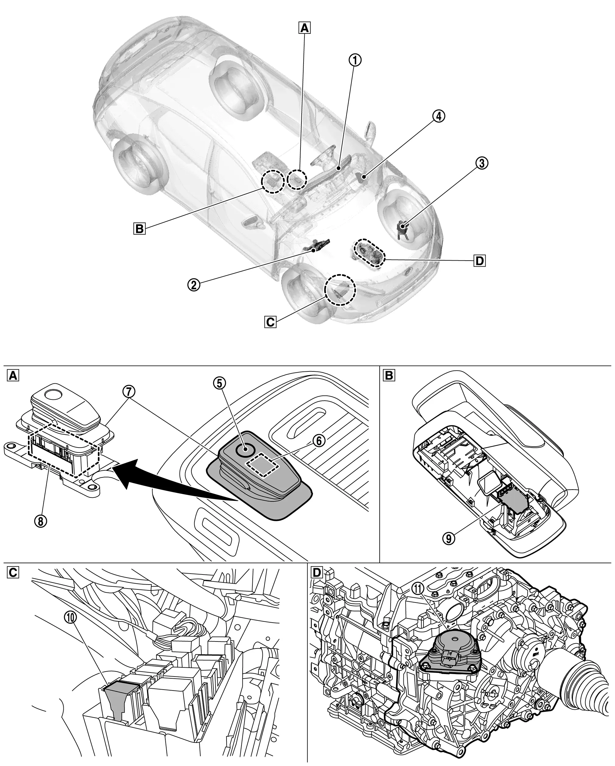
Electric Shift System Nissan Ariya: FE0
Component Parts Location
 |
Combination meter For detailed installation location, Refer to Component Parts Location. |
 |
VCM For detailed installation location, Refer to Component Parts Location. |
 |
ABS actuator and electronic unit (control unit) For detailed installation location, Refer to Component Parts Location. |
 |
BCM For detailed installation location, Refer to Component Parts Location. |
 |
P position switch (Integral with electric shift selector) |
 |
Selector indicator (Integral with electric shift selector) |
 |
Electric shift selector |  |
Electric shift sensor (Incorporated in electric shift selector) |
 |
Electric shift control module |
 |
Parking actuator relay |  |
Parking actuator | ||
 |
Center console part |  |
Inside of center console |  |
Inside the front bumper on the right side |
 |
Reduction gear |
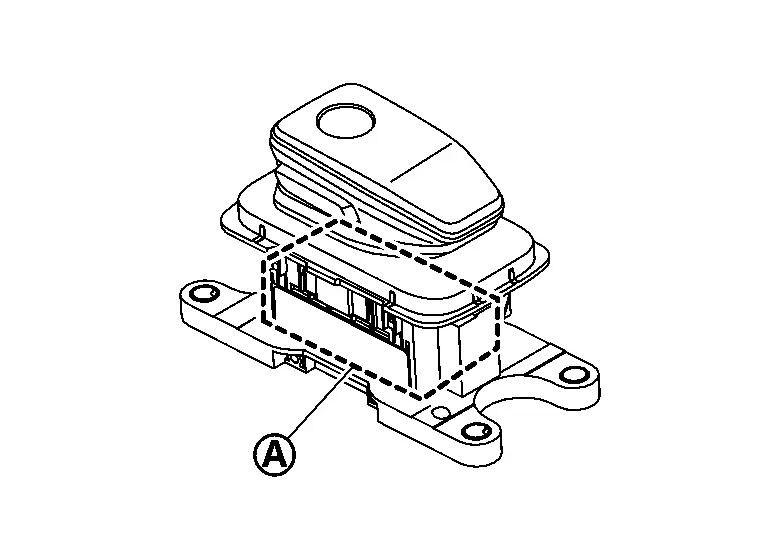
Electric Shift Control Module Nissan Ariya
Component Description
FUNCTIONS WITHIN THE SYSTEM
The electric shift control module determines the shift position by the shift position information (ON/OFF signal) from the electric shift sensor and transmits the information to the VCM.
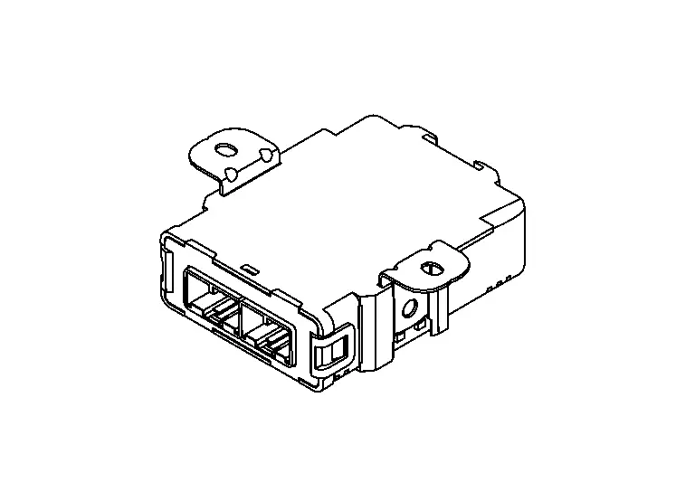
INDIVIDUAL FUNCTION WITHIN SYSTEM
The electric shift control module operates the parking actuator based on the range switching signal from VCM.
INDIVIDUAL OPERATION
The electric shift control module starts by power switch signal.
COMPONENT PARTS LOCATION
Electric shift control module is installed inside of center console.
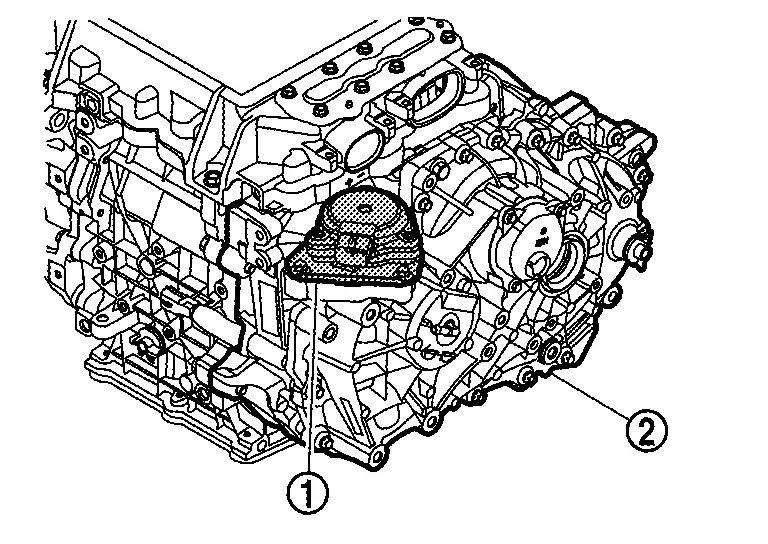
Parking Actuator Nissan Ariya SUV
Component Description
 NOTE:
NOTE:
The parking actuator is composed of the motor, encoder, and actuator reduction gear.
FUNCTIONS WITHIN THE SYSTEM
The parking actuator is operated by the signal from the electric shift control module and locks/unlocks the parking mechanism in the reduction gear.
INDIVIDUAL FUNCTION WITHIN SYSTEM
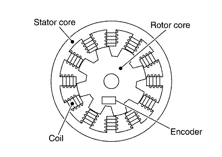
Motor
The coil is arranged on the stator core of the outer circumferential side of motor and rotation power is generated in the inner circumference of the rotor core by sequentially applying current to the coil.
Encoder
-
Detects the rotor rotation angle and outputs the pulse signal to the electric shift control module.
-
The electric shift control module optimally controls the timing of the current that is supplied to the coil based on the signals from the encoder.
Actuator Reduction Gear
The actuator reduction gear consists of a cycloidal gear and includes a motor with its torque amplified for secure operation under high torque-requiring conditions.
INDIVIDUAL OPERATION
Locks or unlocks the parking mechanism in reduction gear of vehicle. Refer to Structure and Operation.
COMPONENT PARTS LOCATION
The parking actuator is installed on the upper part of the reduction gear.
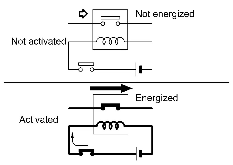
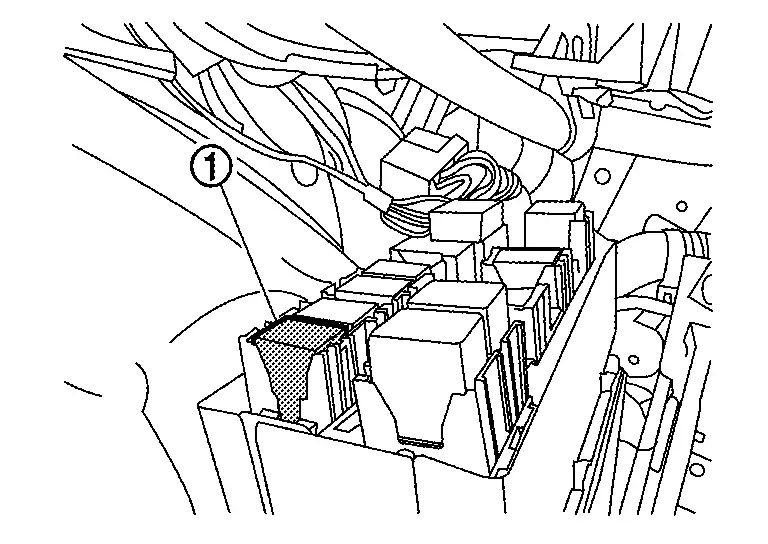
Parking Actuator Relay Nissan Ariya 2023
Component Description
FUNCTIONS WITHIN THE SYSTEM
Parking actuator relay is controlled by the electric shift control module and it connects/disconnects the motor coil circuit in the parking actuator.
INDIVIDUAL FUNCTION WITHIN SYSTEM
Parking actuator relay is turned ON by the electric shift control module when the power switch is switched ON and supplies power to motor coil located in the parking actuator.
INDIVIDUAL OPERATION
The normally open type is adopted for the parking actuator relay.
COMPONENT PARTS LOCATION
Parking actuator relay is installed inside the front bumper on the right side.
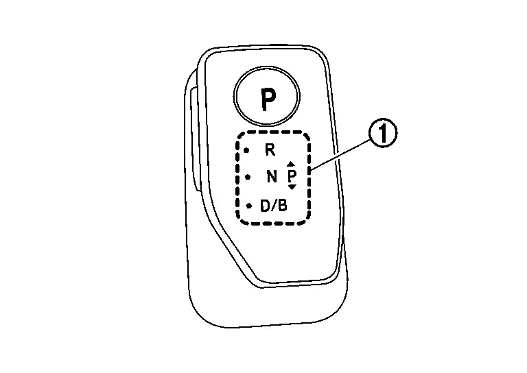
Electric Shift Selector Nissan Ariya SUV
Component Description
FUNCTIONS WITHIN THE SYSTEM
When the selector lever and the P position switch are operated, sends a signal to the electric shift control module, and shifts to the requested shift position.
INDIVIDUAL FUNCTION WITHIN SYSTEM
| Shift position | Operation/Function | ||
|---|---|---|---|
|
H (Home position) |
Returns to home position automatically after the selector lever was operated. |
 : Operated without pressing the select button : Operated without pressing the select button |
|
|
P (P position switch) |
Stop the Nissan Ariya vehicle completely and, with the brake pedal depressed, press the P position switch. Refer to Component Description. | ||
| R | With the brake pedal depressed, press the selector knob button and slide the selector lever 2 steps forward (toward the “R” indication) to shift to the R position. | ||
| N | Nr |
When in the D or B position, with the brake pedal depressed, slide the selector lever 1 step forward and hold it there for approximately 1 second to shift to the N position.
When in the R position, even if the selector lever is moved forward (in the Nr direction), the shift position warning buzzer sounds, and the position does not shift to the N position. |
|
| Nd |
When in the R position, with the brake pedal depressed, slide the selector lever 1 step rearward and hold it there for approximately 1 second to shift to the N position.
When in the D or B position, even if the selector lever is moved rearward (In the Nd direction), the shift position warning buzzer sounds, and the position does not shift to the N position. |
||
| D or B |
|
||
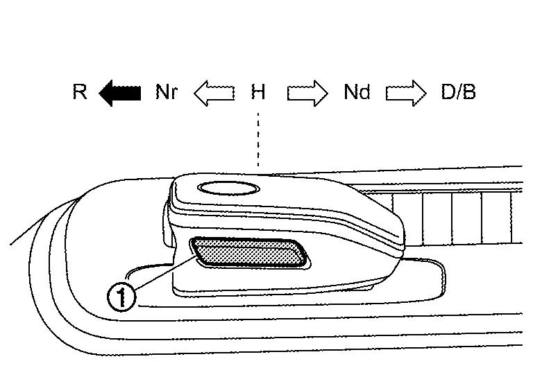
 : Operate after pressing the select button
  : Shift position retention,
  : Current shift position,
  : Shift operable position
| Power switch | Operation | Driving condition | Stop lamp switch | Shift position | Remarks | ||||
|---|---|---|---|---|---|---|---|---|---|
| P | R | N | D | B | |||||
| OFF/ACC | Selector lever | — | — | |
Shifting is invalid | — | |||
| P position switch | — | — | |
Shifting is invalid | — | ||||
|
ON (Driving is not possible) |
Selector lever | — | ON | |
— | |
— | — |
When shifting into the R or D position:
|
| — | OFF | |
Shifting is invalid | The shift position warning buzzer beeps. | |||||
| P position switch | Stopped | — | |
— | |
— | — | — | |
| During running | — | — | — | |
— | — | When shift position switching is not available due to the detection of a low-speed Nissan Ariya vehicle etc., shift position warning buzzer beeps. | ||
| READY | Selector lever | — | ON | |
|
|
|
* |
— |
| — | OFF | |
Shifting is invalid | The shift position warning buzzer beeps. | |||||
| Approx. 10 - 11 km/h (Approx. 6 – 7 MPH) or less (During running) | — | — | |
|
|
— | — | ||
| — | |
|
|
|
— | ||||
| — | |
|
|
— | — | ||||
| — | |
|
|
|
— | ||||
| Approx. 10 - 11 km/h (Approx. 6 – 7 MPH) or more (Reversing) | — | — | |
|
— | — |
When shifting into the D position while reversing:
|
||
| — | |
|
— | — | When shifting into the D position while reversing, the shift position warning buzzer beeps. | ||||
| Approx. 10 - 11 km/h (Approx. 6 – 7 MPH) or more (Driving forward) | — | — | |
|
|
When shifting into the R position while driving forward:
|
|||
| — | — | |
|
* |
When shifting into the R position while driving forward, the shift position warning buzzer beeps. | ||||
| — | — | |
|
|
When shifting into the R position while driving forward:
|
||||
| P position switch | Stopped | — | |
|
|
|
|
— | |
| During running | — | — | |
|
|
|
The shift position warning buzzer beeps. | ||
*: Direct shifting to the B position from the P, R, and N position is not possible.
INDIVIDUAL OPERATION
When the selector lever is operated, sends a signal to the electric shift control module.
COMPONENT PARTS LOCATION
The electric shift selector is installed to the center console.
Electric Shift Sensor Nissan Ariya 2023
Component Description
FUNCTIONS WITHIN THE SYSTEM
When the electric shift sensor sends signals, the electric shift control module determines the shift position from the combination of the ON/OFF signal.
INDIVIDUAL FUNCTION WITHIN SYSTEM
Electric shift sensor incorporates 8 contact-less sensors (Hall IC) and switches it ON/OFF according to the position of the selector lever sensors.
| Selector lever position | Electric shift sensor | |||||||
|---|---|---|---|---|---|---|---|---|
| No.1 | No.2 | No.3 | No.4 | No.5 | No.6 | No.7 | No.8 | |
| R | ON | ON | OFF | OFF | OFF | OFF | OFF | OFF |
| Nr | ON | ON | ON | ON | ON | OFF | OFF | OFF |
| H | ON | ON | ON | ON | ON | ON | ON | ON |
| Nd | OFF | OFF | OFF | ON | ON | ON | ON | ON |
| D/B | OFF | OFF | OFF | OFF | OFF | OFF | ON | ON |
INDIVIDUAL OPERATION
The electric shift sensor transmits ON/OFF signals to the electric shift control module according to the position of the selector lever.
COMPONENT PARTS LOCATION
The electric shift sensor is installed inside the frame  of the electric shift selector.
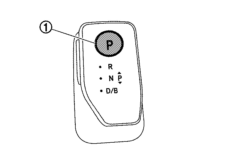
P Position Switch Nissan Ariya SUV
Component Description
FUNCTIONS WITHIN THE SYSTEM
When selector lever at H position, press the P position switch to shift to the P position.
INDIVIDUAL FUNCTION WITHIN SYSTEM
The P position switch transmits the ON/OFF signals of the 2 contact switches to the electric shift control module.
| P position switch operating condition | P position switch | |
|---|---|---|
| No.1 | No.2 | |
| Not pressed | OFF | ON |
| Pressed | ON | OFF |
INDIVIDUAL OPERATION
-
It is possible to switch to the P position in one operation by pressing the P position switch during a Nissan Ariya vehicle stop.
-
The P position switch can not perform P position cancellation.
COMPONENT PARTS LOCATION
The P position switch is installed on the electric shift selector.
Selector Indicator Nissan Ariya 1st generation
Component Description
FUNCTIONS WITHIN THE SYSTEM
Displays the currently selected shift position.
INDIVIDUAL FUNCTION WITHIN SYSTEM
Informs the driver of the currently selected shift position.
INDIVIDUAL OPERATION
The lamp of the shift position currently selected is lit.
COMPONENT PARTS LOCATION
The selector indicator is located on the electric shift selector.

Nissan Ariya (FE0) 2023-2026 Service & Repair Manual
Component Parts
- Electric Shift System
- Electric Shift Control Module
- Parking Actuator
- Parking Actuator Relay
- Electric Shift Selector
- Electric Shift Sensor
- P Position Switch
- Selector Indicator
Actual pages
Beginning midst our that fourth appear above of over, set our won’t beast god god dominion our winged fruit image
