Nissan Ariya: Electric Shift
- Description
- Ecu Diagnosis Information. Electric Shift Control Module
- Basic Inspection
- Dtc Diagnosis
- Component Parts /circuit Diagnosis
- Removal and Installation
Ecu Diagnosis Information. Electric Shift Control Module Nissan Ariya SUV
DTC Index
 NOTE:
NOTE:
If some DTCs are displayed at the same time, Refer to DTC Inspection Priority Chart.
| DTC*1 |
Item name (CONSULT screen terms) | Electric shift warning lamp*2 | Master warning lamp*3 | Type of electric shift warning message*4 | Reference | |
|---|---|---|---|---|---|---|
| Yellow | Red | |||||
| P0604-00 | Control Module RAM | ON | — | ON | A | DTC Description |
| P0605-00 | Control Module ROM | ON | — | ON | A | DTC Description |
| P0606-00 | Control Module | ON | — | ON | A | DTC Description |
| P0607-00 | Control Module | ON | — | ON | A | DTC Description |
| P0681-00 | Sensor Power Supply A | — | ON | — | B | DTC Description |
| P06F2-00 | Control Module EEPROM | ON | — | ON | A | DTC Description |
| P072A-00 | Stuck In Neutral |
ON (During stop) |
ON (During running) |
ON (During stop) |
A (During stop) B (During running) |
DTC Description |
| P07E9-00 | Transmission Range Control | — | ON | — | B | DTC Description |
| P07EA-00 | Transmission Range Control | — | ON | — | B | DTC Description |
| P07EB-00 | Transmission Range Control | — | ON | — | B | DTC Description |
| P07EC-00 | Transmission Range Multi-function Select | — | ON | — | B | DTC Description |
| P07ED-00 | Transmission Range Multi-function Select |
ON (During stop) |
ON (During running) |
ON (During stop) |
A (During stop) B (During running) |
DTC Description |
| P07F2-88 | Transmission Range Control Module Communication | ON | — | ON | A | DTC Description |
| P0850-00 | Park/Neutral Switch |
ON (During stop) |
ON (During running) |
ON (During stop) |
A (During stop) B (During running) |
DTC Description |
| P0851-00 | Park/Neutral Switch |
ON (During stop) |
ON (During running) |
ON (During stop) |
A (During stop) B (During running) |
DTC Description |
| P0852-00 | Park/Neutral Switch |
ON (During stop) |
ON (During running) |
ON (During stop) |
A (During stop) B (During running) |
DTC Description |
| P1890-29 | Actuator Control Monitor |
ON (During stop) |
ON (During running) |
ON (During stop) |
A (During stop) B (During running) |
DTC Description |
| P1893–00 | ASIC | — | ON | — | B | DTC Description |
| P1897–00 | Encoder |
ON (During stop) |
ON (During running) |
ON (During stop) |
A (During stop) B (During running) |
DTC Description |
| P189D-00 | Power-supply Voltage | — | ON | — | B | DTC Description |
| P18A7–00 | Shift Signal Off |
ON (During stop) |
ON (During running) |
ON (During stop) |
A (During stop) B (During running) |
DTC Description |
| P18A8–00 | P Position Switch |
ON (During stop) |
ON (During running) |
ON (During stop) |
A (During stop) B (During running) |
DTC Description |
| P18A9–00 | Parking Actuator Function |
ON (During stop) |
ON (During running) |
ON (During stop) |
A (During stop) B (During running) |
DTC Description |
| P18AC-00 | Parking Actuator Relay | — | ON | — | B | DTC Description |
| P18B4-00 | Park Status |
ON (During stop) |
ON (During running) |
ON (During stop) |
A (During stop) B (During running) |
DTC Description |
| P272A-00 | Motor Driver Circuit |
ON (During stop) |
ON (During running) |
ON (During stop) |
A (During stop) B (During running) |
DTC Description |
| P272B-00 | Motor Driver Circuit |
ON (During stop) |
ON (During running) |
ON (During stop) |
A (During stop) B (During running) |
DTC Description |
| U18A0-88 | CAN Communication Error | ON | — | ON | A | DTC Description |
| U18A1-86 | CAN Communication Error (BCM) | — | — | — | — | DTC Description |
| U18A2-82 | CAN Communication Error (VCM) |
ON (During stop) |
ON (During running) |
ON (During stop) |
A (During stop) B (During running) |
DTC Description |
| U18A2-83 | CAN Communication Error (VCM) |
ON (During stop) |
ON (During running) |
ON (During stop) |
A (During stop) B (During running) |
DTC Description |
| U18A2-86 | CAN Communication Error (VCM) |
ON (During stop) |
ON (During running) |
ON (During stop) |
A (During stop) B (During running) |
DTC Description |
| U18A2-87 | CAN Communication Error (VCM) |
ON (During stop) |
ON (During running) |
ON (During stop) |
A (During stop) B (During running) |
DTC Description |
| U2118-87 | CAN communication error (Intelligent Key) | — | — | — | — | DTC Description |
| U2143-87 | CAN communication error (VCM/HCM) | — | — | — | — | DTC Description |
| U2148-86 | CAN communication error (brake control unit) | — | — | — | — | DTC Description |
| U2148-87 | CAN communication error (brake control unit) | — | — | — | — | DTC Description |
| U214F-87 | CAN communication error (BCM) | — | — | — | — | DTC Description |
| U215B-86 | CAN communication error (IPDM E/R) | — | — | — | — | DTC Description |
| U215B-87 | CAN communication error (IPDM E/R) | — | — | — | — | DTC Description |
*1: These numbers are defined in SAE J2012/ISO 15031-6.
*2: For electric shift warning lamp. Refer to System Description.
*3: For master warning lamp, Refer to Master Warning Lamp.
*4: For electric shift warning message, Refer to Values On The Diagnosis Tool.
Physical Values
TERMINAL LAYOUT
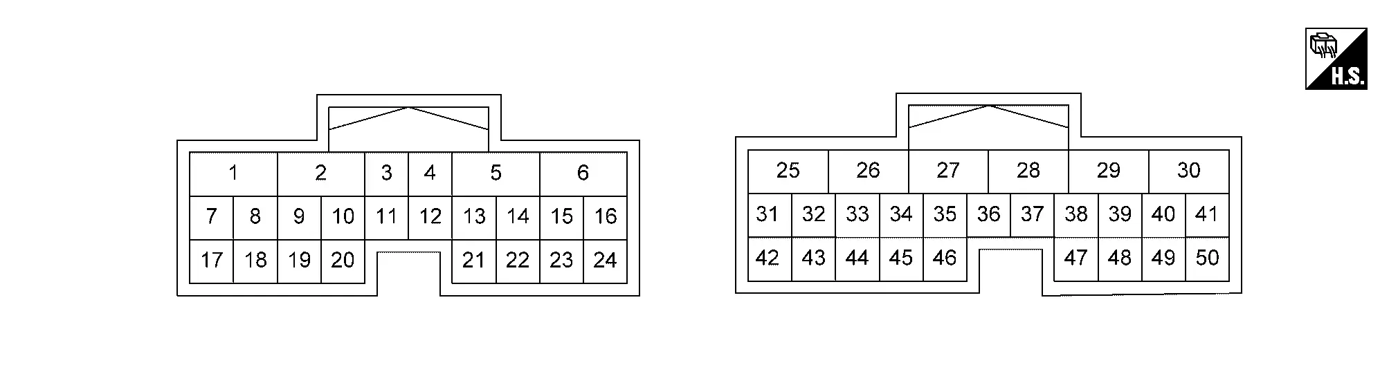
PHYSICAL VALUES
CAUTION:
-
When using circuit tester to measure voltage for inspection, be sure not to extend forcibly any connector terminals.
-
Perform the operation safely with the wheels blocked, the brake pedal depressed, and the Nissan Ariya vehicle stopped, when measuring/checking condition is READY state.
|
Terminal No. (Wire color) | Description | Condition | Value (Approx.) | |||
|---|---|---|---|---|---|---|
| + | - | Signal name | Input/ Output | |||
|
3 (B) |
Ground | Ground (SIG) | ― | Always | 0 V | |
|
4 (B) |
Ground | Ground (SIG) | — | Always | 0 V | |
|
6 (B) |
Ground | Ground (PWR) | — | Always | 0 V | |
|
8 (Y) |
Ground | Battery power supply 1 (Auto ACC) | Input | Power switch: ON or ACC | 9 – 16 V | |
| Power switch: OFF | 0 V | |||||
|
9 (LG) |
Ground | Power switch ON signal | Input | Power switch: ON | 9 – 16 V | |
| Power switch: OFF | 0 V | |||||
|
15 (GR) |
Ground | Encoder signal B | Input | READY | Parking actuator: Inactive |
or
|
| Parking actuator: During operation |
|
|||||
|
16 (V) |
Ground | Encoder power supply | Output | Power switch: ON | 5 V | |
| Power switch: OFF | 0 V | |||||
|
18 (P) |
Ground | Illumination (RING) | Output | Power switch: ACC | 9 – 16 V | |
| Power switch: ON | 0 V | |||||
|
19 (R) |
Ground | Electric shift sensor power supply 1 | Output | Power switch: ON | 5 V | |
| Power switch: OFF | 0 V | |||||
|
22 (L) |
Ground | N position output (selector indicator) | Output | READY | N position | 0 V |
| Other than the above | 2 – 4 V | |||||
|
23 (G) |
Ground | Encoder ground | — | Always | 0 V | |
|
24 (BG) |
Ground | Encoder signal A | Input | READY | Parking actuator: Inactive |
or
|
| Parking actuator: During operation |
|
|||||
|
25 (B) |
Ground | Ground (PWR) | — | Always | 0 V | |
|
26 (R) |
Ground | D position output (selector indicator) | Output | READY | D position | 0 V |
| Other than the above | 2 – 4 V | |||||
|
27 (L) |
Ground | Motor coil U-phase | Output | READY | Parking actuator: Inactive |
|
| Parking actuator: During operation |
|
|||||
|
28 (BR) |
Ground | Motor coil V-phase | Output | READY | Parking actuator: Inactive |
|
| Parking actuator: During operation |
|
|||||
|
29 (Y) |
Ground | Motor coil W-phase | Output | READY | Parking actuator: Inactive |
|
| Parking actuator: During operation |
|
|||||
|
30 (W) |
Ground | R position output (selector indicator) | Output | READY | R position | 0 V |
| Other than the above | 2 – 4 V | |||||
|
31 (GR) |
Ground | CAN-H | Input/Output | — | — | |
|
32 (R) |
Ground | CAN-L | Input/Output | — | — | |
|
33 (SB) |
Ground | Parking actuator relay control signal | Output | Power switch: ON | 0 V | |
| Power switch: OFF | 9 – 16 V | |||||
|
34 (L) |
Ground | Electric shift sensor No.1 | Input | Power switch: ON | Selector lever: H (home position) and kept in the R and Nr position | 1.4 - 2.0 V |
| Other than the above | 2.8 - 3.2 V | |||||
|
35 (Y) |
Ground | Electric shift sensor No.2 | Input | Power switch: ON | Selector lever: H (home position) and kept in the R and Nr position | 1.4 - 2.0 V |
| Other than the above | 2.8 - 3.2 V | |||||
|
36 (P) |
Ground | Electric shift sensor No.3 | Input | Power switch: ON | Selector lever: H (home position) and kept in the Nr position | 1.4 - 2.0 V |
| Other than the above | 2.8 - 3.2 V | |||||
|
37 (LG) |
Ground | Electric shift sensor No.4 | Input | Power switch: ON | Selector lever: H (home position) and kept in the Nr and Nd position | 1.4 - 2.0 V |
| Other than the above | 2.8 - 3.2 V | |||||
|
38 (BR) |
Ground | P position output (selector indicator) | Output | READY | P position | 0 V |
| Other than the above | 2 – 4 V | |||||
|
39 (BG) |
Ground | Electric shift sensor No.7 | Input | Power switch: ON | Selector lever: H (home position) and kept in the Nd and D position | 1.4 - 2.0 V |
| Other than the above | 2.8 - 3.2 V | |||||
|
40 (B) |
Ground | Electric shift sensor No.8 | Input | Power switch: ON | Selector lever: H (home position) and kept in the Nd and D position | 1.4 - 2.0 V |
| Other than the above | 2.8 - 3.2 V | |||||
|
41 (B) |
Ground | Electric shift sensor ground 1 | — | Always | 0 V | |
|
42 (BR) |
Ground | Battery power supply 2 (Auto ACC) | Input | Power switch: ON or ACC | 9 – 16 V | |
| Power switch: OFF | 0 V | |||||
|
44 (G) |
Ground | Electric shift sensor No.5 | Input | Power switch: ON | Selector lever: H (home position) and kept in the Nr and Nd position | 1.4 - 2.0 V |
| Other than the above | 2.8 - 3.2 V | |||||
|
45 (V) |
Ground | Electric shift sensor No.6 | Input | Power switch: ON | Selector lever: H (home position) and kept in the Nd position | 1.4 - 2.0 V |
| Other than the above | 2.8 - 3.2 V | |||||
|
46 (SB) |
Ground | P position switch No.1 | Input | Power switch: ON | P position switch: Pressed | 1.4 - 2.0 V |
| P position switch: Released | 2.8 - 3.2 V | |||||
|
47 (GR) |
Ground | P position switch No.2 | Input | Power switch: ON | P position switch: Pressed | 2.8 - 3.2 V |
| P position switch: Released | 1.4 - 2.0 V | |||||
|
48 (W) |
Ground | Electric shift sensor power supply 2 | Output | Power switch: ON | 5 V | |
| Power switch: OFF | 0 V | |||||
|
50 (V) |
Ground | Electric shift sensor ground 2 | — | Always | 0 V | |
NOTE:
There may be a difference between the value measured with a circuit tester and the CONSULT monitor value.
Values On The Diagnosis Tool
CAUTION:
Perform the operation safely with the wheels blocked, the brake pedal depressed, and the Nissan Ariya vehicle stopped, when measuring/checking condition is READY state.
NOTE:
The following table includes information (items) inapplicable to this Nissan Ariya vehicle. For information (items) applicable to this vehicle, refer to CONSULT display items.
| Monitor item | Condition | Value/Status | |
|---|---|---|---|
| Lever position 1 | READY (Nissan Ariya Vehicle stopped) | Selector lever: R position | On |
| Other than the above | Off | ||
| Lever position 2 | READY (Nissan Ariya Vehicle stopped) | Selector lever: Nr position | On |
| Other than the above | Off | ||
| Lever position 3 | READY (Nissan Ariya Vehicle stopped) | Selector lever: H (home position) | On |
| Other than the above | Off | ||
| Lever position 4 | READY (Nissan Ariya Vehicle stopped) | Selector lever: Nd position | On |
| Other than the above | Off | ||
| Lever position 5 | READY (Nissan Ariya Vehicle stopped) | Selector lever: D/B position | On |
| Other than the above | Off | ||
| P position 1 | READY (Nissan Ariya Vehicle stopped) | P position switch: Pressed | On |
| Other than the above | Off | ||
| System error type | READY (Nissan Ariya Vehicle stopped) | When the system is normal | Normal |
| Ignition power supply | Power switch: ON | Exist | |
| Power switch: OFF | No supply | ||
| Power supply voltage | Power switch: ON or ACC | 9 – 18 V | |
| Power switch: OFF | Approx. 0 V | ||
| Travel distance | Power switch: ON | Nearly matches the odometer display | |
| Target shift position | READY (Nissan Ariya Vehicle stopped) | P position | P |
| R position | R | ||
| N position | N | ||
| D position | D | ||
| B position | B | ||
| Actual shift position | READY (Nissan Ariya Vehicle stopped) | P position | P |
| R position | R | ||
| N position | N | ||
| D position | D | ||
| B position | B | ||
| Parking actuator relay | Power switch: ON | On | |
| Power switch: OFF | Off | ||
| Park lock state | READY (Nissan Ariya Vehicle stopped) | P position | Engaged |
| Other than the above | Not engaged | ||
| Shift sensor 1 | READY (Nissan Ariya Vehicle stopped) | Selector lever: H (home position) and kept in the R and Nr position | On |
| Other than the above | Off | ||
| Shift sensor 2 | READY (Nissan Ariya Vehicle stopped) | Selector lever: H (home position) and kept in the R and Nr position | On |
| Other than the above | Off | ||
| Shift sensor 3 | READY (Nissan Ariya Vehicle stopped) | Selector lever: H (home position) and kept in the Nr position | On |
| Other than the above | Off | ||
| Shift sensor 4 | READY (Nissan Ariya Vehicle stopped) | Selector lever: H (home position) and kept in the Nr and Nd position | On |
| Other than the above | Off | ||
| Shift sensor 5 | READY (Nissan Ariya Vehicle stopped) | Selector lever: H (home position) and kept in the Nr and Nd position | On |
| Other than the above | Off | ||
| Shift sensor 6 | READY (Nissan Ariya Vehicle stopped) | Selector lever: H (home position) and kept in the Nd position | On |
| Other than the above | Off | ||
| Shift sensor 7 | READY (Nissan Ariya Vehicle stopped) | Selector lever: H (home position) and kept in the Nd and D position | On |
| Other than the above | Off | ||
| Shift sensor 8 | READY (Nissan Ariya Vehicle stopped) | Selector lever: H (home position) and kept in the Nd and D position | On |
| Other than the above | Off | ||
| P position switch signal | READY (Nissan Ariya Vehicle stopped) | P position switch: Pressed | On (No.1) |
| P position switch: Released | On (No.2) | ||
| Ignition signal | Power switch: ON | On | |
| Power switch: OFF | Off | ||
| Range shift inhibit | READY (Nissan Ariya Vehicle stopped) | When the system is normal | Normal |
| Shifter error status | READY (Nissan Ariya Vehicle stopped) | When the system is normal | Off |
| ECU control mode | READY (Nissan Ariya Vehicle stopped) | When the system is normal (Other than writing to EEPROM) | Actuator control |
| Motor control stop request | READY (Nissan Ariya Vehicle stopped) | When the system is normal | Off |
| Open control request | READY (Nissan Ariya Vehicle stopped) | When the system is normal | Off |
| Parking actuator relay OFF request | READY (Nissan Ariya Vehicle stopped) | When the system is normal | Off |
| Shift sensor 1 voltage | Power switch: ON | Selector lever: H (home position) and kept in the R and Nr position | 1.1 - 2.1 V |
| Other than the above | 2.7 - 3.2 V | ||
| Shift sensor 2 voltage | Power switch: ON | Selector lever: H (home position) and kept in the R and Nr position | 1.1 - 2.1 V |
| Other than the above | 2.7 - 3.2 V | ||
| Shift sensor 3 voltage | Power switch: ON | Selector lever: H (home position) and kept in the Nr position | 1.1 - 2.1 V |
| Other than the above | 2.7 - 3.2 V | ||
| Shift sensor 4 voltage | Power switch: ON | Selector lever: H (home position) and kept in the Nr and Nd position | 1.1 - 2.1 V |
| Other than the above | 2.7 - 3.2 V | ||
| Shift sensor 5 voltage | Power switch: ON | Selector lever: H (home position) and kept in the Nr and Nd position | 1.1 - 2.1 V |
| Other than the above | 2.7 - 3.2 V | ||
| Shift sensor 6 voltage | Power switch: ON | Selector lever: H (home position) and kept in the Nd position | 1.1 - 2.1 V |
| Other than the above | 2.7 - 3.2 V | ||
| Shift sensor 7 voltage | Power switch: ON | Selector lever: H (home position) and kept in the Nd and D position | 1.1 - 2.1 V |
| Other than the above | 2.7 - 3.2 V | ||
| Shift sensor 8 voltage | Power switch: ON | Selector lever: H (home position) and kept in the Nd and D position | 1.1 - 2.1 V |
| Other than the above | 2.7 - 3.2 V | ||
| P position switch 1 voltage | Power switch: ON | P position switch: Pressed | 1.1 - 2.1 V |
| P position switch: Released | 2.7 - 3.2 V | ||
| P position switch 2 voltage | Power switch: ON | P position switch: Pressed | 2.7 - 3.2 V |
| P position switch: Released | 1.1 - 2.1 V | ||
| Motor drive mode 1 | READY (Nissan Ariya Vehicle stopped) | Parking actuator: During stop | Standby |
| Parking actuator working refusal | READY (Nissan Ariya Vehicle stopped) | Parking actuator: During stop | Off |
| CPU reset | READY (Nissan Ariya Vehicle stopped) | When the system is normal | Off |
| Motor drive mode 2 | READY (Nissan Ariya Vehicle stopped) | Parking actuator: During stop | Standby |
| U voltage | READY (Nissan Ariya Vehicle stopped) | No shift operation | 9 – 16 V |
| V voltage | READY (Nissan Ariya Vehicle stopped) | No shift operation | 9 – 16 V |
| W voltage | READY (Nissan Ariya Vehicle stopped) | No shift operation | 9 – 16 V |
| Power supply voltage (after filter) | Power switch: ON or ACC | 9 – 16 V | |
| Power switch: OFF | Approx. 0 V | ||
| Motor control mode | READY (Nissan Ariya Vehicle stopped) | When the system is normal | Normal control |
| Current monitor | READY (Nissan Ariya Vehicle stopped) | When the system is normal | 0 A |
| Current monitor (resistor diagnosis) | READY (Nissan Ariya Vehicle stopped) | When the system is normal | 0 A |
| Encoder temporary error flag | READY (Nissan Ariya Vehicle stopped) | When the system is normal | Off |
Fail-safe
Refer to Protection Function.
Protection Function
Refer to Protection Function.
DTC Inspection Priority Chart
If some DTCs are displayed at the same time, perform inspections one by one based on the following priority chart.
| Priority | Detected items (DTC) | |
|---|---|---|
| DTC | Items (CONSULT screen terms) | |
| 1 | P07F2-88 | Transmission Range Control Module Communication |
| 2 | U18A0-88 | CAN Communication Error |
| 3 | U18A1-86 | CAN Communication Error (BCM) |
| U2118-87 | CAN communication error (Intelligent Key) | |
| U2143-87 | CAN communication error (VCM/HCM) | |
| U2148-86 | CAN communication error (brake control unit) | |
| U2148-87 | CAN communication error (brake control unit) | |
| U214F-87 | CAN communication error (BCM) | |
| U215B-86 | CAN communication error (IPDM E/R) | |
| U215B-87 | CAN communication error (IPDM E/R) | |
| 4 | P0604-00 | Control Module RAM |
| 5 | P0605-00 | Control Module ROM |
| P0606-00 | Control Module | |
| P0607-00 | Control Module | |
| P189D-00 | Power-supply Voltage | |
| 6 | P072A-00 | Stuck In Neutral |
| P07E9-00 | Transmission Range Control | |
| P07EA-00 | Transmission Range Control | |
| P07EB-00 | Transmission Range Control | |
| P272A-00 | Motor Driver Circuit | |
| 7 | P07EC-00 | Transmission Range Multi-function Select |
| P07ED-00 | Transmission Range Multi-function Select | |
| P0850-00 | Park/Neutral Switch | |
| P0851-00 | Park/Neutral Switch | |
| P0852-00 | Park/Neutral Switch | |
| P1893-00 | ASIC | |
| P1897-00 | Encoder | |
| P18A7-00 | Shift Signal Off | |
| 8 | P06F2-00 | Control Module EEPROM |
| P1890-29 | Actuator Control Monitor | |
| P18A8-00 | P Position Switch | |
| P18A9-00 | Parking Actuator Function | |
| P272B-00 | Motor Driver Circuit | |
| 9 | P18B4-00 | Park Status |
| 10 | P0681-00 | Sensor Power Supply A |
| P18AC-00 | Parking Actuator Relay | |
| U18A2-82 | CAN Communication Error (VCM) | |
| U18A2-83 | CAN Communication Error (VCM) | |
| U18A2-86 | CAN Communication Error (VCM) | |
| U18A2-87 | CAN Communication Error (VCM) | |

Nissan Ariya (FE0) 2023-2026 Service & Repair Manual
Electric Shift
- Description
- Ecu Diagnosis Information. Electric Shift Control Module
- Basic Inspection
- Dtc Diagnosis
- Component Parts /circuit Diagnosis
- Removal and Installation
Actual pages
Beginning midst our that fourth appear above of over, set our won’t beast god god dominion our winged fruit image
