Nissan Ariya: Component Parts
- Ev Control System
- Vcm
- 12v Main Relay
- Accelerator Pedal Position Sensor
- Cooling Fan Control Module
- Electric Water Pump Relay
- Electric Water Pump 1
- Ev Power Relay
- Pre-Charge Relay
- Refrigerant Pressure Sensor
- Stop Lamp Switch
- System Main Relay 1
Ev Control System Nissan Ariya: FE0
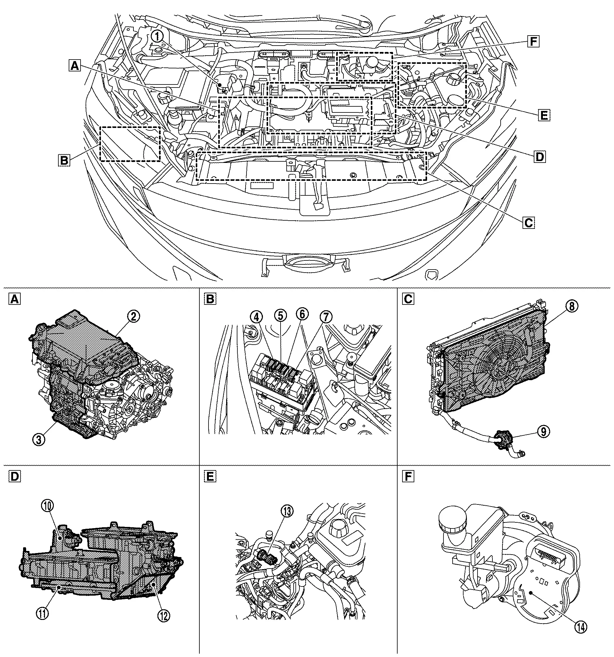
Component Parts Location
Motor Room Compartment
 |
12V battery For details on the installation position, Refer to Component Parts Location. |
 |
Inverter (front) For details on the installation position, Refer to Component Parts Location. |
 |
Front traction motor For details on the installation position, Refer to Component Parts Location. |
 |
Electric water pump relay |  |
12V main relay |  |
Traction motor oil pump relay For details on the installation position, Refer to Component Parts Location. |
 |
EV power relay |  |
Cooling fan control module |  |
Electric water pump 1 |
 |
On-board charger For details on the installation position, Refer to Component Parts Location. |
 |
DC/DC converter For details on the installation position, Refer to Component Parts Location. |
 |
High voltage junction box For details on the installation position, Refer to Component Parts Location. |
 |
Refrigerant pressure sensor |  |
Electrically-driven intelligent brake unit For details on the installation position, Refer to Component Parts Location. |
||
 |
Lower side of electric power train |  |
Front right side of motor room, inside of relay box |  |
Radiator area |
 |
Upper side of electric power train |  |
Rear center side of motor room |  |
Rear right side of motor room |
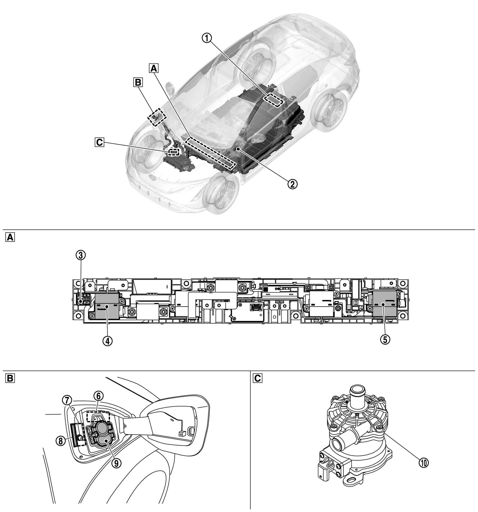
66kWh Li-ion Battery, 2WD models
Vehicle Compartment

|
Li-ion battery controller For details on the installation position, Refer to Component Parts Location. |
|
VSP control unit | |
Pre-charge relay |
|
System main relay 1 | |
System main relay 2 | |
Charge connector lock actuator For details on the installation position, Refer to Component Parts Location. |
|
Charge port lid actuator For details on the installation position, Refer to Component Parts Location. |
|
Charge port light For details on the installation position, Refer to Component Parts Location. |
|
Charge port For details on the installation position, Refer to Component Parts Location. |
|
Electric water pump 2 | ||||
|
Li-ion battery junction box | |
Charge port | |
Right upper side of motor room |
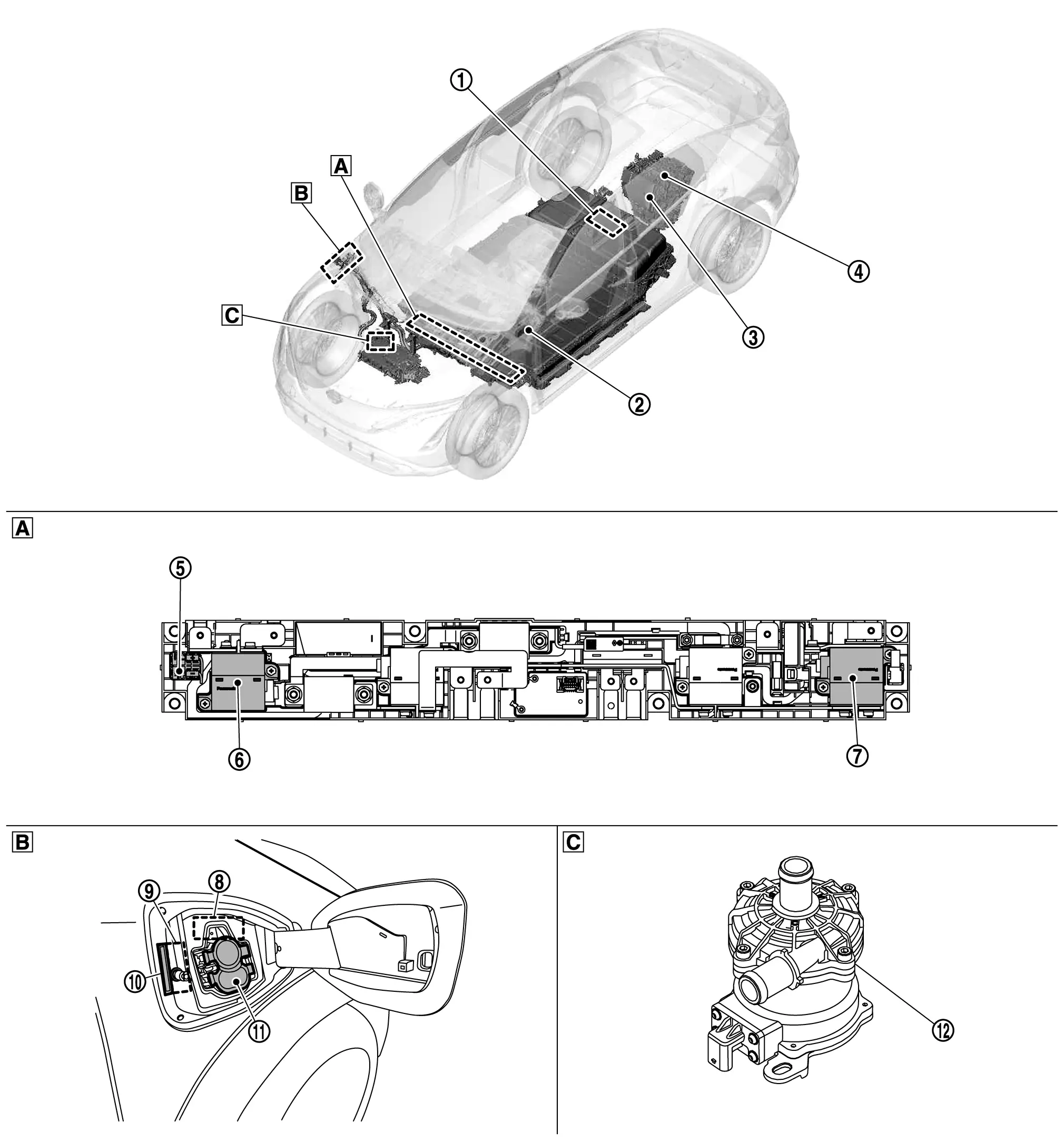
66kWh Li-ion Battery, AWD models
Vehicle Compartment

|
Li-ion battery controller For details on the installation position, Refer to Component Parts Location. |
|
VSP control unit | |
Inverter (rear) |
|
Rear traction motor | |
Pre-charge relay | |
System main relay 1 |
|
System main relay 2 | |
Charge connector lock actuator For details on the installation position, Refer to Component Parts Location. |
|
Charge port lid actuator For details on the installation position, Refer to Component Parts Location. |
|
Charge port light For details on the installation position, Refer to Component Parts Location. |
|
Charge port For details on the installation position, Refer to Component Parts Location. |
|
Electric water pump 2 |
|
Li-ion battery junction box | |
Charge port | |
Right upper side of motor room |
91kWh Li-ion Battery, 2WD models
Vehicle Compartment
|
Li-ion battery controller For details on the installation position, Refer to Component Parts Location. |
|
VSP control unit | |
Pre-charge relay |
|
System main relay 1 | |
System main relay 2 | |
Charge connector lock actuator For details on the installation position, Refer to Component Parts Location. |
|
Charge port lid actuator For details on the installation position, Refer to Component Parts Location. |
|
Charge port light For details on the installation position, Refer to Component Parts Location. |
|
Charge port For details on the installation position, Refer to Component Parts Location. |
|
Electric water pump 2 | ||||
|
Li-ion battery junction box | |
Charge port | |
Right upper side of motor room |
91kWh Li-ion Battery, AWD models
Vehicle Compartment
|
Li-ion battery controller For details on the installation position, Refer to Component Parts Location. |
|
VSP control unit | |
Inverter (rear) |
|
Rear traction motor | |
Pre-charge relay | |
System main relay 1 |
|
System main relay 2 | |
Charge connector lock actuator For details on the installation position, Refer to Component Parts Location. |
|
Charge port lid actuator For details on the installation position, Refer to Component Parts Location. |
|
Charge port light For details on the installation position, Refer to Component Parts Location. |
|
Charge port For details on the installation position, Refer to Component Parts Location. |
|
Electric water pump 2 |
|
Li-ion battery junction box | |
Charge port | |
Right upper side of motor room |
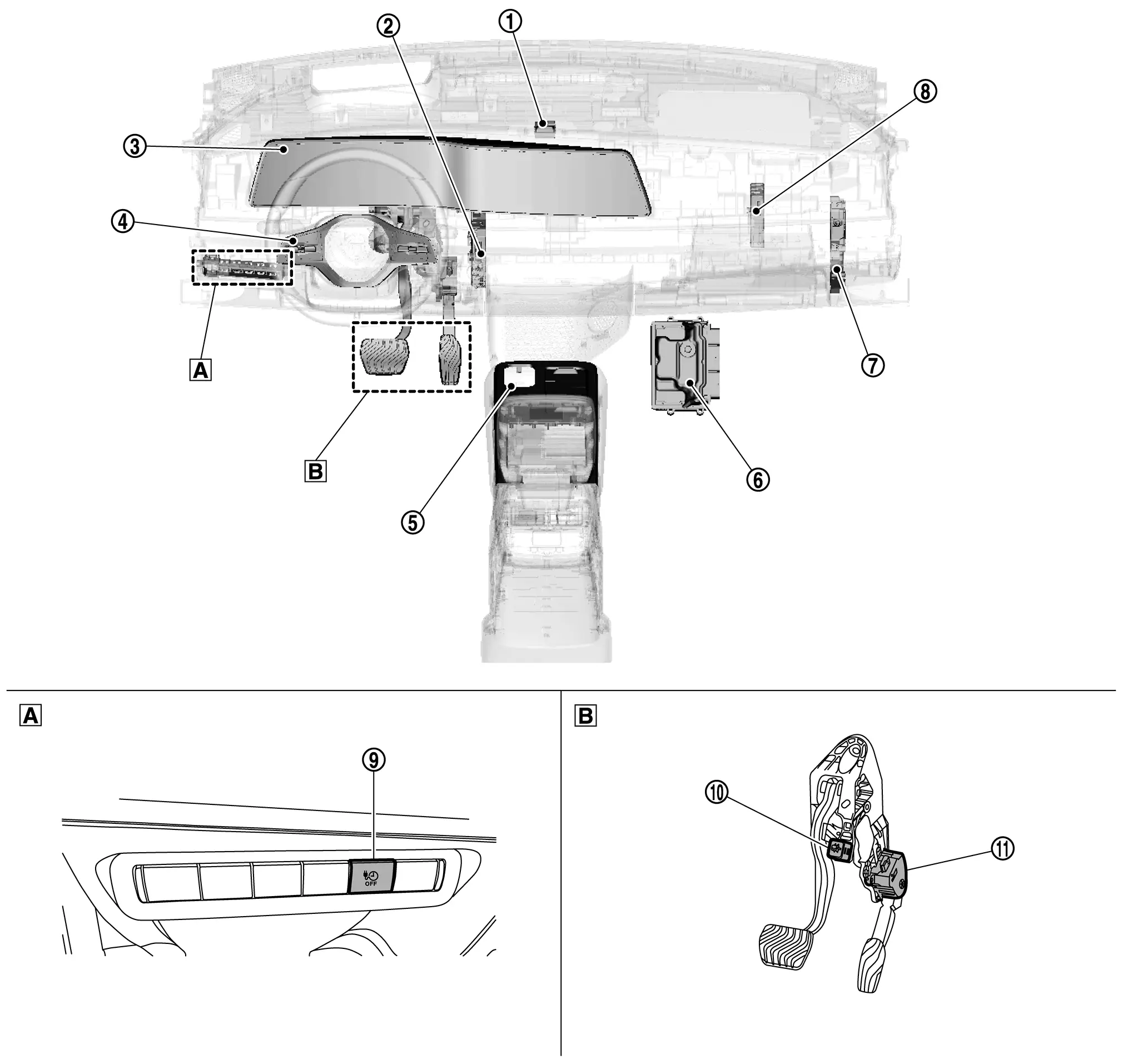
Interior Compartment
|
Charging status indicator For details on the installation position, Refer to Component Parts Location. |
|
TCU For details on the installation position, Refer to Component Parts Location. |
|
Combination meter For details on the installation position, Refer to Component Parts Location. |
|
ProPILOT Assist/ProPILOT Assist 2.0 steering switch | |
e-Pedal switch For details on the installation position, Refer to Component Parts Location. |
|
VCM |
|
BCM For details on the installation position, Refer to Component Parts Location. |
|
A/C auto amp. For details on the installation position, Refer to Component Parts Location. |
|
Immediate charging switch For details on the installation position, Refer to Component Parts Location. |
|
Stop lamp switch | |
Accelerator pedal position sensor | ||
|
Switch panel | |
Accelerator pedal and brake pedal upper part |
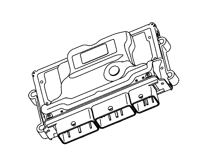
Vcm Nissan Ariya 2026
Component Description
FUNCTIONS WITHIN THE SYSTEM
VCM (Vehicle control module) judges the vehicle status according to signals from various sensors and ECUs, and controls EV system in a comprehensive manner.
INDIVIDUAL FUNCTION WITHIN THE SYSTEM
-
The VCM consists of the microcomputer and input/output connectors for signal.
-
When even the ignition switch is turned OFF, power is supplied continuously from the battery for maintaining the DTC and memory functions.
-
The VCM includes a self-diagnosis function for simplifying trouble diagnosis.
-
VCM has a gateway function for EV system CAN communication and CAN communication.
It enables communication between an ECU performing CAN communication and an ECU performing EV system CAN communication.
INDIVIDUAL OPERATION
The VCM controls a variety of EV systems. Refer to System Description.
COMPONENT PARTS LOCATION
VCM is installed beside the foot of co-driver of the Interior Compartment.
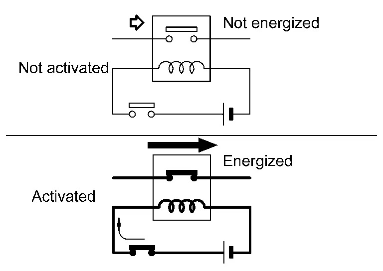
12v Main Relay Nissan Ariya 2023
Component Description
FUNCTIONS WITHIN THE SYSTEM
12V main relay supplies 12V power to VCM and Li-ion battery. When the EV system needs to be started up, VCM turns on the 12V main relay and supplies 12V power to VCM and Li-ion battery.
INDIVIDUAL FUNCTION WITHIN THE SYSTEM
12V main relay connects and disconnects the power supply circuit by ON / OFF of the relay switch.
INDIVIDUAL OPERATION
12V main relay adopts normal open type.
COMPONENT PARTS LOCATION
12V main relay is installed in the relay box of front right side of the vehicle.
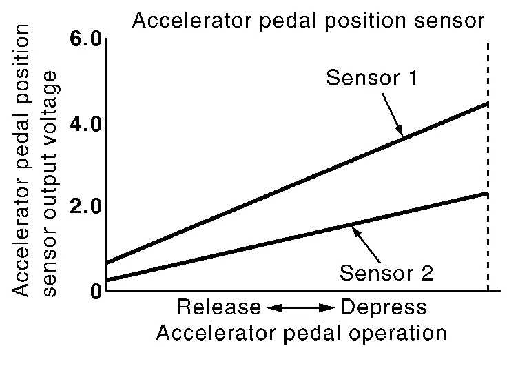
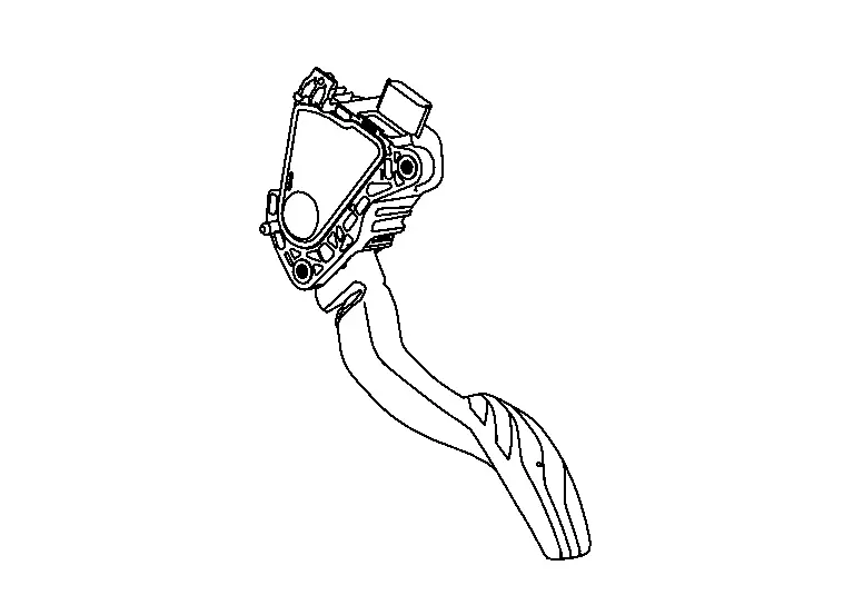
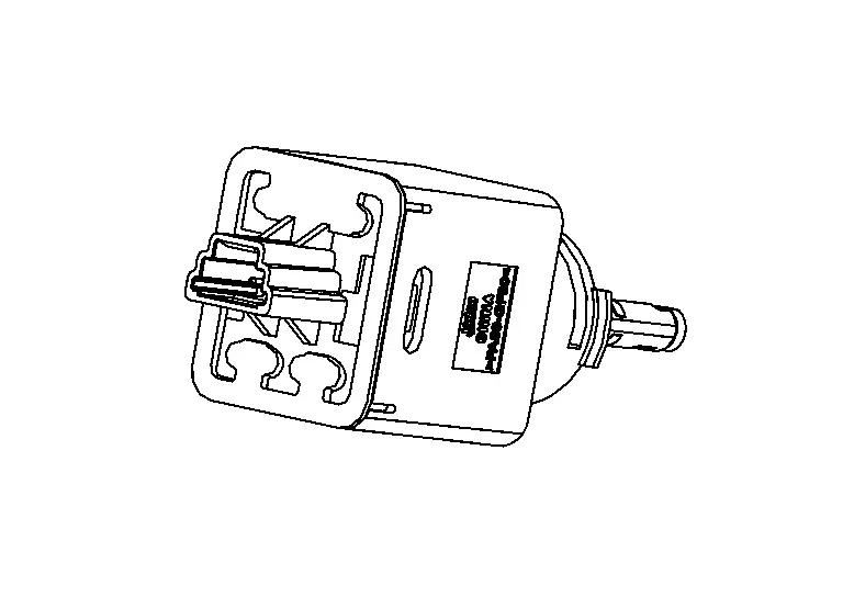
Accelerator Pedal Position Sensor Nissan Ariya: FE0
Component Description
FUNCTIONS WITHIN THE SYSTEM
The accelerator pedal sensor is integrated with the accelerator pedal. This sensor is a potentiometer that detects the acceleration pedal stroke, converts it to a voltage signal, and transmits the signal to VCM.
Upon a POWER ON cycle, VCM learns the fully closed position of the acceleration pedal from the accelerator pedal position sensor signal.
INDIVIDUAL FUNCTION WITHIN THE SYSTEM
Detects the amount that the accelerator pedal is depressed.
INDIVIDUAL OPERATION
The sensor transmits its signals through dual lines, providing a minimum driving function even if either line malfunctions.
COMPONENT PARTS LOCATION
The accelerator pedal position sensor is installed on the upper end of the accelerator pedal assembly.
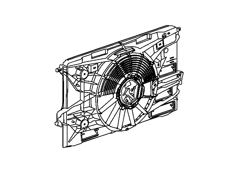
Cooling Fan Control Module Nissan Ariya: FE0
Component Description
FUNCTIONS WITHIN THE SYSTEM
VCM transmits the cooling fan control signal to IPDM E/R.
The cooling fan control module drives the cooling fan motor so that the cooling fan speed is controlled in accordance with the control signal from IPDM E/R.
INDIVIDUAL FUNCTION WITHIN THE SYSTEM
The cooling fan control module is drives the cooling fan motor.
INDIVIDUAL OPERATION
The cooling fan control module receives control signal from IPDM E/R.
COMPONENT PARTS LOCATION
The cooling fan control module is integrated into the cooling fan.
Electric Water Pump Relay Nissan Ariya 1st generation
Component Description
FUNCTIONS WITHIN THE SYSTEM
The electric water pump relay supplies 12V power to the electric water pump 1 and electric water pump 2. VCM turns on the electric water pump relay during power switch ON and supplies power to the electric water pump 1 and electric water pump 2.
INDIVIDUAL FUNCTION WITHIN THE SYSTEM
The electric water pump relay connects and disconnects the power supply circuit by ON / OFF of the relay switch.
INDIVIDUAL OPERATION
The electric water pump adopts normal open type.
COMPONENT PARTS LOCATION
The electric water pump is installed in the relay box of front right side of the vehicle.
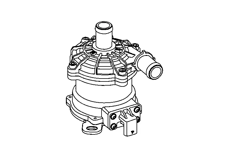
Electric Water Pump 1 Nissan Ariya first Gen
Component Description
FUNCTIONS WITHIN THE SYSTEM
VCM controls the electric water pump 1 to adjust the amount of pressure feed according to the vehicle speed and water temperature.
INDIVIDUAL FUNCTION WITHIN THE SYSTEM
The electric water pump 1 feeds coolant by pressure, which circulates in the high voltage system cooling circuit.
INDIVIDUAL OPERATION
The electric water pump 1 integrates an interface circuit that monitors the pump function for any malfunction, and it transmits a malfunction signal to VCM if necessary.
COMPONENT PARTS LOCATION
The electric water pump 1 is installed in the lower side of the electric compressor.
Ev Power Relay Nissan Ariya 2026
Component Description
FUNCTIONS WITHIN THE SYSTEM
EV power relay supplies 12V power to each electric device. VCM turns on EV power relay during power switch ON and supplies power to each electric device.
INDIVIDUAL FUNCTION WITHIN THE SYSTEM
EV power relay connects and disconnects the power supply circuit by ON / OFF of the relay switch.
INDIVIDUAL OPERATION
EV power relay adopts normal open type.
COMPONENT PARTS LOCATION
EV power is installed in the relay box of front right side of the vehicle.
Pre-Charge Relay Nissan Ariya SUV
Component Description
FUNCTIONS WITHIN THE SYSTEM
The pre-charge relay is controlled by VCM. When high voltage power is required, VCM activates the pre-charge relay before activating the system main relay to prevent abrupt application of high voltage.
INDIVIDUAL FUNCTION WITHIN THE SYSTEM
The pre-charge relay connects and disconnects the power supply circuit by ON / OFF of the relay switch.
COMPONENT PARTS LOCATION
The pre-charge relay is integrated in the battery junction box of the Li-ion battery.
The Li-ion battery is installed under the floor of the vehicle.
Refrigerant Pressure Sensor Nissan Ariya first Gen
Component Description
FUNCTIONS WITHIN THE SYSTEM
VCM calculates refrigerant pressure based on the voltage signal from refrigerant pressure sensor transmits a refrigerant pressure signal to the A/C auto amp. via EV system CAN communication.
INDIVIDUAL FUNCTION WITHIN THE SYSTEM
The refrigerant pressure sensor converts refrigerant pressure to a voltage.
INDIVIDUAL OPERATION
The refrigerant pressure sensor uses an electrostatic volume pressure transducer to convert refrigerant pressure to voltage.

COMPONENT PARTS LOCATION
The refrigerant pressure sensor is installed on the refrigerant piping of rear part of motor room.
Stop Lamp Switch Nissan Ariya SUV
Component Description
FUNCTIONS WITHIN THE SYSTEM
VCM inputs the brake pedal position switch signal (stop lamp SW1 signal) from the stop lamp switch, or VCM receives the stop lamp switch signal (stop lamp SW2 signal) from BCM via CAN communication, and performs various control by judging the brake pedal status.
INDIVIDUAL FUNCTION WITHIN THE SYSTEM
The stop lamp switch integrates switch of dual lines and inputs the brake pedal operation status to VCM and BCM.
INDIVIDUAL OPERATION
The stop lamp switch integrates switch of dual line and perform ON/OFF according to the brake pedal operation.
STOP LAMP SWITCH SIGNAL (NORMAL OPEN)
The stop lamp switch signal (stop lamp SW2) side of the stop lamp switch is a normal open type. The contacts of the stop lamp switch are normally open. When the brake pedal is depressed, the contacts are closed, and the circuit is conducted.
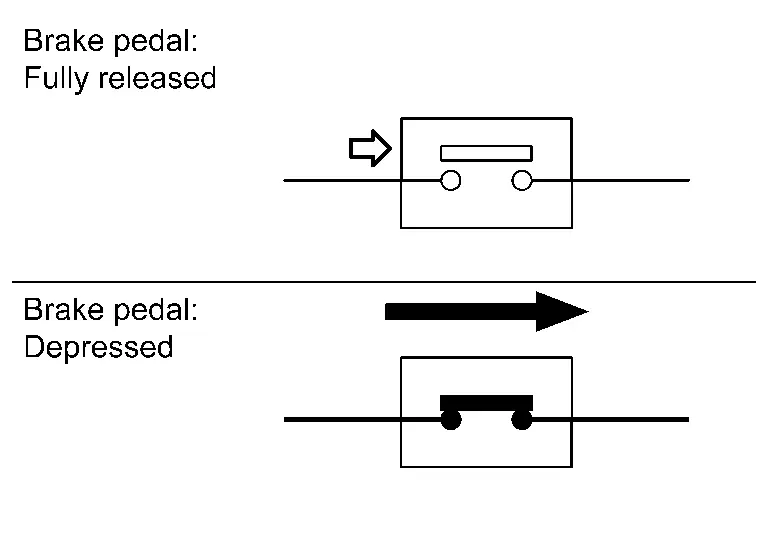
BRAKE PEDAL POSITION SWITCH SIGNAL (NORMAL CLOSE TYPE)
The brake pedal position switch signal (stop lamp SW1 signal) side of the stop lamp switch is a normal close type switch, therefore the contact is normally closed. When the brake pedal is depressed, the contact is opened and the circuit is cut off.
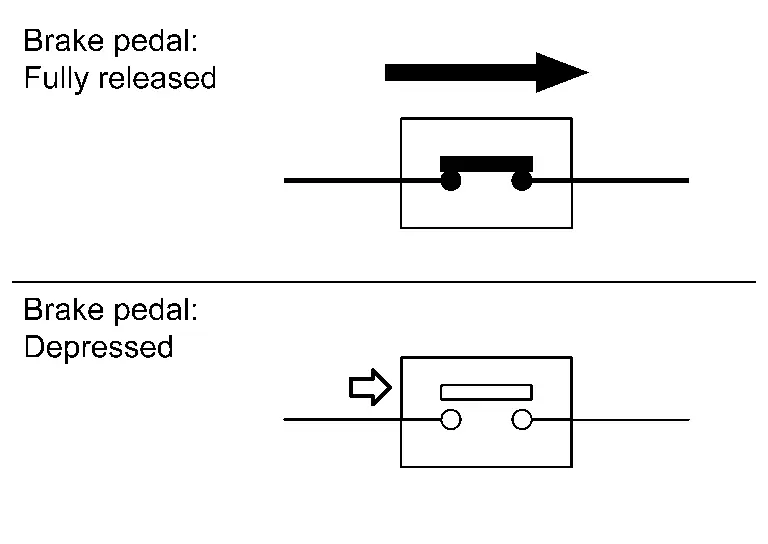
COMPONENT PARTS LOCATION
The stop lamp switch is installed to the brake pedal bracket.
System Main Relay 1 Nissan Ariya first Gen
Component Description
FUNCTIONS WITHIN THE SYSTEM
The system main relay 1 that is controlled by VCM connects and disconnects the high-voltage circuit (+) side and Li-ion battery.
When the pre-charge to the condenser in the inverter (front) is completed while high voltage power is supplied, VCM activates the system main relay 1 ON to supply power from the Li-ion battery to the EV system.
INDIVIDUAL FUNCTION WITHIN THE SYSTEM
The system main relay 1 connects and disconnects of the power supply circuit by ON / OFF of the relay switch.
COMPONENT PARTS LOCATION
The system main relay 1 is integrated in the battery junction box of Li-ion battery .
The Li-ion battery is installed under the floor of the vehicle.

Nissan Ariya (FE0) 2023-2026 Service & Repair Manual
Component Parts
- Ev Control System
- Vcm
- 12v Main Relay
- Accelerator Pedal Position Sensor
- Cooling Fan Control Module
- Electric Water Pump Relay
- Electric Water Pump 1
- Ev Power Relay
- Pre-Charge Relay
- Refrigerant Pressure Sensor
- Stop Lamp Switch
- System Main Relay 1
Actual pages
Beginning midst our that fourth appear above of over, set our won’t beast god god dominion our winged fruit image
