Nissan Ariya: Ecu Diagnosis Information. Vcm
DTC Index
×: Applicable —: Not applicable
| DTC | Items | EV system warning lamp | Trip | Reference page |
|---|---|---|---|---|
| P0000-00 | Internal error | × | 1 | DTC Description |
| P0504-00 | Brake Switch | — | 2 | DTC Description |
| P0530-16 | A/C refrigerant pressure sensor A | — | 2 | DTC Description |
| P0530-17 | A/C refrigerant pressure sensor A | — | 2 | DTC Description |
| P0560-16 | System voltage | × | 1 | DTC Description |
| P0560-17 | System voltage | × | 1 | DTC Description |
| P0560-22 | System voltage | — | 1 | DTC Description |
| P0560-61 | System voltage | × | 2 | DTC Description |
| P05B1-02 | Active grille air shutter B | — | 1 | DTC Description |
| P05B1-07 | Active grille air shutter B | — | 1 | DTC Description |
| P05B1-77 | Active grille air shutter B | — | 1 | DTC Description |
| P05B1-96 | Active grille air shutter B | — | 1 | DTC Description |
| P05B1-97 | Active grille air shutter B | — | 1 | DTC Description |
| P05B1-F7 | Active grille air shutter B | — | 1 | DTC Description |
| P0641-16 | Sensor reference voltage A | × | 1 | DTC Description |
| P0641-17 | Sensor reference voltage A | × | 1 | DTC Description |
| P0651-16 | Sensor Reference Voltage B | × | 1 | DTC Description |
| P0651-17 | Sensor Reference Voltage B | × | 1 | DTC Description |
| P0657-11 | Actuator supply voltage B | — | 1 | DTC Description |
| P0657-12 | Actuator supply voltage B | — | 1 | DTC Description |
| P0657-13 | Actuator supply voltage B | — | 1 | DTC Description |
| P0685-12 | ECM power relay | — | 2 | DTC Description |
| P0685-14 | ECM power relay | — | 2 | DTC Description |
| P0697-16 | Sensor reference voltage C | × | 1 | DTC Description |
| P0697-17 | Sensor reference voltage C | × | 1 | DTC Description |
| P0A7E-F1 | Battery pack pressure sensor | — | 1 | DTC Description |
| P0AA6-23 | High voltage battery voltage system isolation | × | 1 or 2 | DTC Description |
| P0AE1-73 | High voltage battery precharge contactor | × | 1 | DTC Description |
| P0AE2-72 | High voltage battery precharge contactor | × | 1 | DTC Description |
| P0AE2-73 | High voltage battery precharge contactor | × | 1 | DTC Description |
| P0B33-63 | High voltage service disconnect | × | 1 | DTC Description |
| P0CA6-19 | High voltage battery charging current | — | 1 | DTC Description |
| P0D0A-11 | Battery charge system positive contactor A | × | Immediate detection | DTC Description |
| P0D0A-12 | Battery charge system positive contactor A | × | Immediate detection | DTC Description |
| P0D0A-13 | Battery charge system positive contactor A | × | Immediate detection | DTC Description |
| P0D11-11 | Battery charge system negative contactor A | × | Immediate detection | DTC Description |
| P0D11-12 | Battery charge system negative contactor A | × | Immediate detection | DTC Description |
| P0D11-13 | Battery charge system negative contactor A | × | Immediate detection | DTC Description |
| P0D98-11 | Battery charger coupler unlock control | × | Immediate detection | DTC Description |
| P0D98-12 | Battery charger coupler unlock control | × | Immediate detection | DTC Description |
| P0D98-13 | Battery charger coupler unlock control | × | Immediate detection | DTC Description |
| P1001-78 | Battery coolant heater connect | × | 1 | DTC Description |
| P102C-01 | Component Indicating a Failure | × | Immediate detection | DTC Description |
| P102D-01 | Electric water pump | × | 1 | DTC Description |
| P102D-7B | Electric water pump | × | 1 | DTC Description |
| P102D-94 | Electric water pump | × | 1 | DTC Description |
| P102D-96 | Electric water pump | × | 1 | DTC Description |
| P102D-98 | Electric water pump | × | 1 | DTC Description |
| P1033-11 | High voltage PTC heater | — | 1 | DTC Description |
| P1035-49 | Internal circuit error | × | 1 | DTC Description |
| P1041-87 | Front traction motor inverter | — | 1 | DTC Description |
| P1041-96 | Front traction motor inverter | — | 1 | DTC Description |
| P104B-16 | Quick charge port temperature sensor | × | Immediate detection | DTC Description |
| P104B-17 | Quick charge port temperature sensor | × | Immediate detection | DTC Description |
| P104C-16 | Quick charge port temperature sensor | × | Immediate detection | DTC Description |
| P104C-17 | Quick charge port temperature sensor | × | Immediate detection | DTC Description |
| P12A8-08 | Brake switch | — | 1 | SIEMDU-493708 |
| P14C1-00 | Stop lamp switch (BCM) | — | 1 | DTC Description |
| P1503-02 | Active grille shutter 1 | — | 1 | DTC Description |
| P1503-07 | Active grille shutter 1 | — | 1 | DTC Description |
| P1503-08 | Active grille shutter 1 | — | 1 | SIEMDU-493735 |
| P1503-77 | Active grille shutter 1 | — | 1 | DTC Description |
| P1503-96 | Active grille shutter 1 | — | 1 | DTC Description |
| P1503-97 | Active grille shutter 1 | — | 1 | DTC Description |
| P1503-F7 | Active grille shutter 1 | — | 1 | DTC Description |
| P1526-00 | Nissan Ariya Vehicle speed sensor | — | 1 | DTC Description |
| P1536-00 | Brake switch | — | 1 | DTC Description |
| P1564-00 | ASCD switch | — | 1 | DTC Description |
| P1572-00 | Brake pedal position switch | — | 1 | DTC Description |
| P1590-11 | EV power relay | × | 1 | DTC Description |
| P1590-12 | EV power relay | × | 1 | DTC Description |
| P1590-13 | EV power relay | × | 1 | DTC Description |
| P1596-96 | High voltage connector interlock | × | 1 | DTC Description |
| P1597-F1 | High voltage connector interlock | × | 1 | DTC Description |
| P1598-96 | Interlock sensors | × | 1 | DTC Description |
| P159A-93 | Electric water pump | × | 1 | DTC Description |
| P159A-96 | Electric water pump | × | 1 | DTC Description |
| P159C-93 | Electric water pump | × | 1 | DTC Description |
| P159C-96 | Electric water pump | × | 1 | DTC Description |
| P159D-23 | High voltage battery | — | 1 | DTC Description |
| P15A2-98 | Traction motor system temperature | — | 1 | DTC Description |
| P15A6-13 | Charging system | — | 1 | DTC Description |
| P15A7-31 | Charging system | — | 1 | DTC Description |
| P15A9-24 | Charging device power supply | — | 1 | DTC Description |
| P15A9-2F | Charging device power supply | — | Immediate detection | DTC Description |
| P15AA-73 | Charging system | × | 1 | DTC Description |
| P15B8-87 | Communication error | — | 2 | DTC Description |
| P15BA-72 | Charging system | × | 1 | DTC Description |
| P15BE-96 | Service plug interlock | × | 1 | DTC Description |
| P15BF-96 | High voltage connector interlock | × | 1 | DTC Description |
| P15C5-78 | High voltage connector interlock | × | 1 | DTC Description |
| P15D3-78 | High voltage connector interlock | × | 1 | DTC Description |
| P15F0-11 | Charge port lid | × | Immediate detection | SIEMDU-493866 |
| P15F0-12 | Charge port lid | × | Immediate detection | DTC Description |
| P15F0-13 | Charge port lid | × | Immediate detection | DTC Description |
| P15FA-11 | Charge port lock | × | Immediate detection | DTC Description |
| P15FA-12 | Charge port lock | × | Immediate detection | DTC Description |
| P15FA-13 | Charge port lock | × | Immediate detection | DTC Description |
| P15FB-01 | Charging system | × | 1 | DTC Description |
| P15FE-16 | Charge port lock | × | Immediate detection | SIEMDU-493888 |
| P15FE-17 | Charge port lock | × | Immediate detection | DTC Description |
| P15FE-64 | Charge port lock | × | Immediate detection | DTC Description |
| P1604-72 | Charge port lock | — | Immediate detection | DTC Description |
| P1604-73 | Charge port lock | × | Immediate detection | DTC Description |
| P1605-63 | Charging system | — | 1 | DTC Description |
| P160C-04 | Internal error | × | 1 | DTC Description |
| P1613-49 | Internal circuit error | × | 1 | DTC Description |
| P161C-49 | Internal circuit error | × | 1 | DTC Description |
| P161C-F1 | Internal circuit error | × | 1 | DTC Description |
| P161E-96 | High voltage connector interlock | × | 1 | DTC Description |
| P161F-96 | High voltage connector interlock | × | 1 | DTC Description |
| P1630-63 | Electric water pump | × | 1 | DTC Description |
| P1638-98 | Charge connector temperature | — | Immediate detection | DTC Description |
| P1638-F9 | Charge connector temperature | — | 1 | DTC Description |
| P163E-62 | Charging system | — | Immediate detection | DTC Description |
| P163F-94 | Charging system | — | 1 | DTC Description |
| P1647-62 | Charging system | — | Immediate detection | DTC Description |
| P164B-64 | Electric shift system | × | 1 | DTC Description |
| P1666-72 | Charging system | — | 1 | DTC Description |
| P166C-1D | Charging device | — | Immediate detection | DTC Description |
| P166E-63 | Electric water pump | × | 1 | DTC Description |
| P1671-81 | Communication error | — | 1 | DTC Description |
| P1672-81 | Communication error | — | 1 | DTC Description |
| P1678-81 | Communication error | — | 1 | DTC Description |
| P1679-81 | Communication error | — | 1 | DTC Description |
| P168A-11 | Precharge relay | × | 1 | DTC Description |
| P168A-12 | Precharge relay | × | 1 | DTC Description |
| P168A-13 | Precharge relay | × | 1 | DTC Description |
| P168B-73 | System main relay | × | 1 | DTC Description |
| P168C-72 | System main relay | × | 1 | DTC Description |
| P168D-11 | System main relay | × | 1 | DTC Description |
| P168D-12 | System main relay | × | 1 | DTC Description |
| P168D-13 | System main relay | × | 1 | DTC Description |
| P168D-72 | System main relay | × | 1 | DTC Description |
| P168E-11 | System main relay | × | 1 | DTC Description |
| P168E-12 | System main relay | × | 1 | DTC Description |
| P168E-13 | System main relay | × | 1 | DTC Description |
| P168E-73 | System main relay | × | 1 | DTC Description |
| P1692-19 | Precharge relay | × | 1 | DTC Description |
| P1693-49 | Communication error | × | 1 | DTC Description |
| P1693-87 | Communication error | × | 1 | DTC Description |
| P1694-49 | Communication error | × | 1 | DTC Description |
| P1694-87 | Communication error | × | 1 | DTC Description |
| P1695-87 | Traction motor system | — | 1 | DTC Description |
| P1695-96 | Traction motor system | — | 1 | DTC Description |
| P16DC-61 | Communication error | — | 1 | DTC Description |
| P1728-19 | High voltage harness temperature | × | 1 | DTC Description |
| P1729-98 | High voltage junction box temperature | × | 1 | DTC Description |
| P172A-11 | High voltage junction box | × | 1 | DTC Description |
| P172A-15 | High voltage junction box | × | 1 | DTC Description |
| P172B-64 | Battery pack pressure sensor | × | 1 | DTC Description |
| P172C-00 | Battery pack pressure sensor | × | Immediate detection | DTC Description |
| P172C-96 | Battery pack pressure sensor | × | Immediate detection | DTC Description |
| P172D-00 | Battery pack pressure sensor | × | Immediate detection | DTC Description |
| P172D-96 | Battery pack pressure sensor | × | Immediate detection | DTC Description |
| P17C6-12 | Power Supply | × | 1 | DTC Description |
| P17C6-14 | Power Supply | × | 1 | DTC Description |
| P18A5-00 | Auto park function cancel | — | 1 | DTC Description |
| P2121-00 | Accelerator pedal position sensor D | — | 1 | Refer to DTC Description. |
| P2122-00 | Accelerator pedal position sensor D | — | 1 | DTC Description |
| P2123-00 | Accelerator pedal position sensor D | — | 1 | DTC Description |
| P2126-00 | Accelerator pedal position sensor E | — | 1 | Refer to DTC Description. |
| P2127-00 | Accelerator pedal position sensor E | — | 1 | DTC Description |
| P2128-00 | Accelerator pedal position sensor E | — | 1 | DTC Description |
| P2138-00 | Accelerator pedal position sensor | — | 1 | DTC Description |
| P2504-21 | Charging system voltage | — | 1 | DTC Description |
| P2504-22 | Charging system voltage | — | 1 | DTC Description |
| P2EBF-73 | Immediate charging switch | — | 1 | DTC Description |
| P3101-61 | VCM | × | 1 | DTC Description |
| P3101-62 | VCM | × or — | 1 or Immediate detection | DTC Description |
| P3194-00 | Communication error | — | 1 | DTC Description |
| P3194-87 | Communication error | — | 1 | DTC Description |
| U007A-00 | Control module communication bus | — | 1 | DTC Description |
| U0273-87 | Communication error | — | 1 | DTC Description |
| U1327-52 | MAC key update | — | 1 | DTC Description |
| U1327-54 | MAC key update | — | 1 | DTC Description |
| U2118-87 | CAN communication error (Intelligent Key) | — | 1 | DTC Description |
| U2148-82 | CAN communication error (brake control unit) | — | 2 | DTC Description |
| U2148-86 | CAN communication error (brake control unit) | — | 2 | DTC Description |
| U2148-87 | CAN communication error (brake control unit) | — | 2 | DTC Description |
| U214E-87 | CAN communication error (combination meter) | — | 1 | DTC Description |
| U214F-57 | CAN communication error (BCM) | — | 1 | DTC Description |
| U214F-82 | CAN communication error (BCM) | — | 1 | DTC Description |
| U214F-86 | CAN communication error (BCM) | — | 1 | DTC Description |
| U214F-87 | CAN communication error (BCM) | — | 1 | DTC Description |
| U2150-82 | CAN communication error (AIRBAG) | — | 1 | DTC Description |
| U2150-87 | CAN communication error (AIRBAG) | — | 1 | DTC Description |
| U2152-57 | CAN communication error advanced driver assistant systems control unit | — | 1 | DTC Description |
| U2152-82 | CAN communication error advanced driver assistant systems control unit | — | 1 | DTC Description |
| U2152-86 | CAN communication error advanced driver assistant systems control unit | — | 1 | DTC Description |
| U2152-87 | CAN communication error advanced driver assistant systems control unit | — | 1 | DTC Description |
| U2153-87 | CAN communication error (Heating, Ventilating, Air Conditioning) ch1 | — | 1 | DTC Description |
| U2154-87 | CAN communication error (MIU) | — | 1 | DTC Description |
| U215B-82 | CAN communication error (IPDM E/R) | — | 2 | DTC Description |
| U215B-86 | CAN communication error (IPDM E/R) | — | 2 | DTC Description |
| U215B-87 | CAN communication error (IPDM E/R) | — | 2 | DTC Description |
| U2165-57 | CAN communication error sonar | — | 1 | DTC Description |
| U2165-82 | CAN communication error sonar | — | 2 | DTC Description |
| U2165-86 | CAN communication error sonar | — | 2 | DTC Description |
| U2165-87 | CAN communication error sonar | — | 2 | DTC Description |
| U2176-57 | CAN communication error (chassis control module/steering angle sensor) | — | 1 | DTC Description |
| U2176-82 | CAN communication error (chassis control module/steering angle sensor) | × | 1 | DTC Description |
| U2176-86 | CAN communication error (chassis control module/steering angle sensor) | × | 1 | DTC Description |
| U2176-87 | CAN communication error (chassis control module/steering angle sensor) | — | 1 | DTC Description |
| U2181-82 | CAN communication error (CPLC) | — | 1 | DTC Description |
| U2181-86 | CAN communication error (CPLC) | — | 1 | DTC Description |
| U2181-87 | CAN communication error (CPLC) | — | 1 | DTC Description |
| U218C-87 | CAN communication error gateway | — | 1 | DTC Description |
| U2212-87 | CAN communication error brake unit | — | 2 | DTC Description |
| U2247-82 | Controller area network communication error (electric shift) | — | 1 | DTC Description |
| U2247-86 | Controller area network communication error (electric shift) | — | 1 | DTC Description |
| U2247-87 | Controller area network communication error (electric shift) | — | 1 | DTC Description |
| U2248-82 | CAN communication error brake control unit | — | 2 | DTC Description |
| U2248-86 | CAN communication error brake control unit | — | 2 | DTC Description |
| U2248-87 | CAN communication error brake control unit | — | 2 | DTC Description |
| U2252-82 | CAN communication error advanced driver assistant systems control unit | — | 1 | DTC Description |
| U2252-87 | CAN communication error advanced driver assistant systems control unit | — | 1 | DTC Description |
| U226B-87 | Controller area network communication error front camera | — | 1 | DTC Description |
| U2252-86 | CAN communication error advanced driver assistant systems control unit | — | 1 | DTC Description |
| U2276-82 | CAN communication error (chassis control module/steering angle sensor) | — | 1 | DTC Description |
| U2276-86 | CAN communication error (chassis control module/steering angle sensor) | — | 1 | DTC Description |
| U2276-87 | CAN communication error (chassis control module/steering angle sensor) | — | 1 | DTC Description |
| U2342-82 | Controller area network communication error (Inverter motor generator/motor generator) | — | 1 | DTC Description |
| U2342-86 | Controller area network communication error (Inverter motor generator/motor generator) | — | 1 | DTC Description |
| U2342-87 | Controller area network communication error (Inverter motor generator/motor generator) | — | 1 | DTC Description |
| U2344-82 | CAN communication error (LBC/BMS) | — | 1 | DTC Description |
| U2344-86 | CAN communication error (LBC/BMS) | — | 1 | DTC Description |
| U2344-87 | CAN communication error (LBC/BMS) | — | 1 | DTC Description |
| U2357-04 | Controller area network communication error (Direct current direct current) | — | 1 | DTC Description |
| U2357-62 | Controller area network communication error (Direct current direct current) | — | 1 | DTC Description |
| U2357-81 | Controller area network communication error (Direct current direct current) | — | 1 | DTC Description |
| U2357-86 | Controller area network communication error (Direct current direct current) | — | 1 | DTC Description |
| U2370-94 | CAN communication error (OBC) | — | 1 | DTC Description |
| U2370-96 | CAN communication error (OBC) | — | 1 | DTC Description |
| U2379-82 | CAN comm error (LBC2/VMR) | — | 2 | DTC Description |
| U2379-86 | CAN comm error (LBC2/VMR) | — | 2 | DTC Description |
| U2379-87 | CAN comm error (LBC2/VMR) | — | 2 | DTC Description |
| U23A1-82 | CAN comm error (INV RE) | — | 2 | DTC Description |
| U23A1-86 | CAN comm error (INV RE) | — | 2 | DTC Description |
| U23A1-87 | CAN comm error (INV RE) | — | 2 | DTC Description |
| U2457-82 | CAN communication error (DCDC) | — | 1 | DTC Description |
| U2457-86 | CAN communication error (DCDC) | — | 1 | DTC Description |
| U2457-87 | CAN communication error (DCDC) | — | 1 | DTC Description |
| U2470-82 | CAN comm error (OBC) | — | 2 | DTC Description |
| U2470-86 | CAN comm error (OBC) | — | 2 | DTC Description |
| U2470-87 | CAN comm error (OBC) | — | 2 | DTC Description |
| U2A02-88 | Comm Bus Off PT-FD | — | 2 | DTC Description |
| U2A0D-88 | Communication error | — | 2 | DTC Description |
| U2A0F-88 | Communication error | — | 1 | DTC Description |
Physical Values
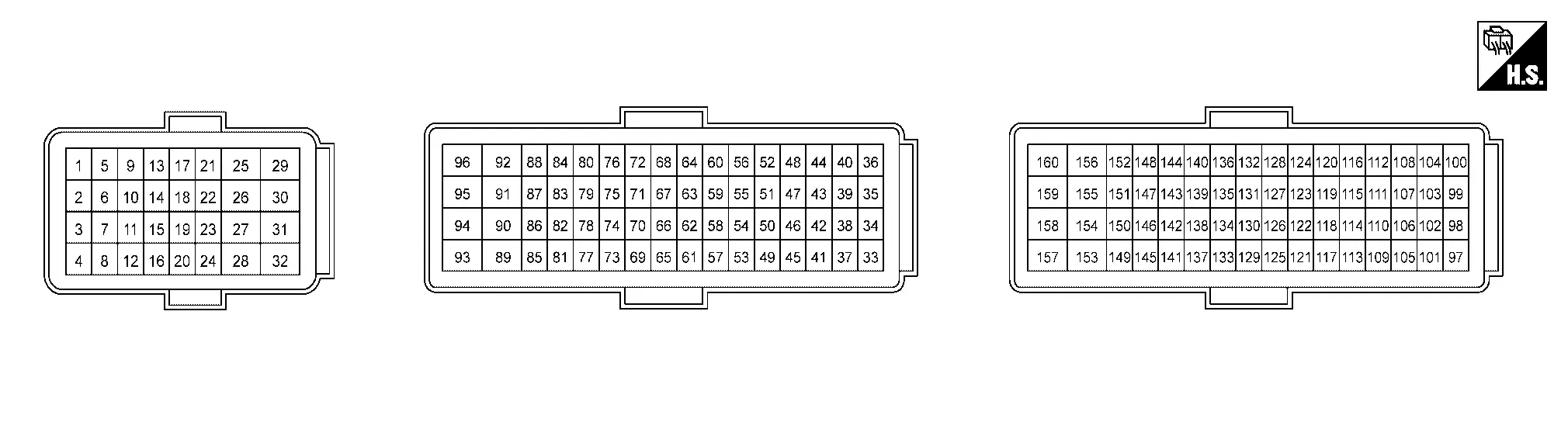
TERMINAL LAYOUT
PHYSICAL VALUES
 NOTE:
NOTE:
Specification data are reference values.
| Terminal No. (Wire color) | Description | Condition | Value (Approx.) | ||
|---|---|---|---|---|---|
| + | — | Signal name | Input/Output | ||
|
3 (R) |
— | CAN-L (Drivetrain CAN communication 2 circuit) | Input/Output | — | — |
|
4 (GR) |
— | CAN-H (Drivetrain CAN communication 2 circuit) | Input/Output | — | — |
|
10 (Y) |
Ground | Immediate charging switch | Input | Immediate charging switch switch: Pressed | 12V battery power supply voltage (12 - 15 V) |
| Immediate charging switch switch: Released | 0 V | ||||
|
13 (R) |
Ground | Power ON power supply | Input | Power switch ON | 12V battery power supply voltage (12 - 15 V) |
|
14 (Y) |
15 (B) |
ProPILOT Assist 2.0 steering switch | Input |
|
0 V approx. |
|
0.5 V approx. | ||||
|
1 V approx. | ||||
|
1.5 V approx. | ||||
|
2.1 V approx. | ||||
|
2.9 V approx. | ||||
|
3.9 V approx. | ||||
| ProPILOT Assist steering switch | Input |
|
0 V approx. | ||
|
1.3 V approx. | ||||
|
2.2 V approx. | ||||
|
3 V approx. | ||||
|
3.7 V approx. | ||||
|
4.3 V approx. | ||||
|
15 (B) |
— | ProPILOT Assist/ProPILOT Assist 2.0 steering switch ground | ― | — | — |
|
17 (G) |
— | CAN-L (EV system CAN 2 circuit) | Input/Output | — | — |
|
18 (L) |
— | CAN-H (EV system CAN 2 circuit) | Input/Output | — | — |
|
20 (W) |
Ground | Stop lamp switch | Input |
|
0 V |
|
12V battery power supply voltage (12 - 15 V) | ||||
|
22 (W) |
24 (B) |
Sensor power supply (Accelerator pedal position sensor 2) | Output | Power switch ON | 5 V approx. |
|
23 (R) |
24 (B) |
Accelerator pedal position sensor 2 | Input |
|
0.3 – 0.45 V |
|
1.95 – 2.4 V | ||||
|
24 (B) |
— | Sensor ground (Accelerator pedal position sensor 2) | ― | — | — |
|
26 (W) |
31 (B) |
Sensor power supply (Accelerator pedal position sensor 1) | Output | Power switch ON | 5 V approx. |
|
28 (B) |
— | VCM ground | ― | — | — |
|
29 (B) |
— | VCM ground | ― | — | — |
|
30 (R) |
31 (B) |
Accelerator pedal position sensor 1 | Input |
|
0.6 - 0.9V |
|
3.9 - 4.8V | ||||
|
31 (B) |
— | Sensor ground (Accelerator pedal position sensor 1) | ― | — | — |
|
32 (B) |
— | VCM ground | ― | — | — |
|
38 (L) |
Ground | Charge port light | Output | Port indicator lamp: ON | 0 V approx. |
| Port indicator lamp: OFF | 12V battery power supply voltage (12 - 15 V) | ||||
|
41 (L) |
Ground | Charging status indicator | Output | Charge ongoing | 5 V approx. |
|
44 (P) |
Ground | Battery pack pressure sensor power supply | Output | Power switch ON | 5 V approx. |
|
46 (SB) |
Ground | EV power relay | Output | Power switch ON or READY | 0 V approx. |
|
52 (BR) |
68 (GR) |
High voltage junction box temperature sensor | Input | Quick charge ongoing | 1.4 – 4.8 approx. |
|
54 (W) |
Ground | e-Pedal switch | Input | e-Pedal switch: Depressed | 12V battery power supply voltage (12 - 15 V) |
| e-Pedal switch: Released | 0 V | ||||
|
62 (R) |
Ground | Charge connector lock status detection switch | Input | Charge connector: Fitting | 9.0 - 11.0 V |
| Charge connector: Non-fitting | Open | ||||
|
64 (LG) |
Ground | Battery pack pressure sensor 2 signal | Input | READY status | 1.0 – 4.0 V |
|
65 (R) |
Ground | EVSE communication | Input/Output | Normal charge ongoing | (-12.6) - (+12.6) V |
| Except the above | 0 V | ||||
|
67 (B) |
— | Battery pack pressure sensor ground | ― | — | — |
|
68 (GR) |
— | Sensor ground (High voltage junction box temperature sensor) | ― | — | — |
|
71 (B) |
— | On-board charger ground | ― | — | — |
|
72 (R) |
Ground | Pre-charge relay | Output | Immediately after power switch operation from OFF to READY | 12V battery power supply voltage (11 - 14 V) |
| Except the above | 0 V | ||||
|
74 (R) |
85 (Y) |
Charge port lid actuator (+) | Output | Charge lid lock actuator : Unlock to Lock | 6 – 7 V approx. |
| Except the above | 0 V | ||||
|
75 (R) |
— | CAN-L (Drivetrain CAN communication 1 circuit) | Input/Output | — | — |
|
76 (GR) |
— | CAN-H (Drivetrain CAN communication 1 circuit) | Input/Output | — | — |
|
78 (BG) |
Ground | Battery pack pressure sensor 1 signal | Input | READY status | 1.0 – 4.0 V |
|
85 (Y) |
74 (R) |
Charge port lid actuator (-) |
Output |
Charge lid lock actuator : Lock to Unlock | 6 – 7 V approx. |
| Except the above | 0 V | ||||
|
88 (L) |
Ground | EVSE connecting signal | Input | Normal charge ongoing | 0.8 – 3.3 V |
| Except the above | 2.5 – 5.0 V | ||||
|
89 (L) |
Ground | System main relay 2 ground | ― | READY or charge ongoing | 12V battery power supply voltage (11 - 14 V) |
| Except the above | 0 V | ||||
|
90 (G) |
Ground | System main relay 1 ground | ― | READY or charge ongoing | 12V battery power supply voltage (11 - 14 V) |
| Except the above | 0 V | ||||
|
91 (SB) |
Ground | Quick charge relay 1 ground | ― | Quick charge ongoing | 12V battery power supply voltage (11 - 14 V) |
| Except the above | 0 V | ||||
|
92 (Y) |
Ground | Quick charge relay 2 ground | ― | Quick charge ongoing | 12V battery power supply voltage (11 - 14 V) |
| Except the above | 0 V | ||||
|
94 (Y) |
95 (LG) |
Charge connector lock actuator (+) | Output | Charge connector lock actuator: Unlock to Lock | 6 - 7 V approx. |
| Except the above | 0 V approx. | ||||
|
95 (LG) |
94 (Y) |
Charge connector lock actuator (-) | Output | Charge connector lock actuator: Lock to Unlock | 6 - 7 V approx. |
| Except the above | 0 V approx. | ||||
|
97 (B) |
Ground | Traction motor oil pump relay | Input | Power switch ON or READY | 0 V approx. |
| Power switch OFF | 12V battery power supply voltage (12 - 15 V) | ||||
|
99 (L) |
Ground | LIN communication | Input/Output | During operating grill shutter | 5 V Approx. |
|
100 (LG) |
Ground | Connection detecting circuit 2 power supply | Output | Power switch ON |
|
|
103 (SB) |
Ground | 12V main relay | Output | Power switch ON or READY | 0 V approx. |
| Power switch OFF | 12V battery power supply voltage (12 - 15 V) | ||||
|
109 (P) |
Ground | Electric water pump 2 signal | Output |
|
|
|
|
||||
|
115 (V) |
— | Sensor ground | ― | — | — |
|
119 (P) |
Ground | Connection detecting circuit 1 signal | Input | When connection detection circuit is established |
|
|
122 (BR) |
Ground | Quick charge relay state signal | Input | Quick charge ongoing | 1.1 - 1.8 V |
| Except the above | 3.5 - 4.5 V | ||||
|
124 (SB) |
Ground | Quick charge port temperature sensor signal 2 | Input | Quick charge ongoing | 1.4 - 4.0 V approx. |
|
132 (R) |
Ground | Connection detecting circuit 1 power supply | Output | Power switch ON |
|
|
133 (B) |
134 (BR) |
Refrigerant pressure sensor | Input | Power switch ON | 5 V Approx. |
|
134 (BR) |
— | Sensor ground (Refrigerant pressure sensor) | ― | — | — |
|
135 (V) |
Ground | Quick charge port temperature sensor signal 1 | Input | Quick charge ongoing | 1.4 - 4.8 V approx. |
|
137 (L) |
— | CAN-H (EV system CAN 1 circuit) | Input/Output | — | — |
|
138 (G) |
— | CAN-L (EV system CAN 1 circuit) | Input/Output | — | — |
|
139 (W) |
Ground | Connection detecting circuit 2 signal | Input | When connection detection circuit is established |
|
|
140 (B) |
— | Sensor ground (Quick charge port temperature sensor) | ― | — | — |
|
143 (G) |
Ground | Electric water pump 1 signal | Output |
|
|
|
|
||||
|
145 (SB) |
134 (BR) |
Sensor power supply (Refrigerant pressure sensor) | Output | Power switch ON | 5 V Approx. |
|
153 (R) |
Ground | 12V battery power supply | Input | Always | 12V battery power supply voltage (12 - 15 V) |
|
158 (LG) |
Ground | 12V battery power supply | Input | During operating VBRH relay | 12V battery power supply voltage (12 - 15 V) |
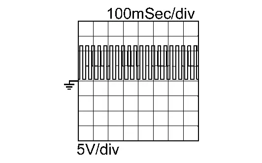
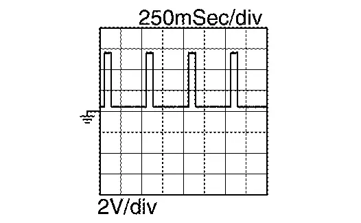
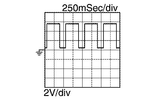
 : Average voltage for pulse signal (Actual pulse signal can be confirmed by oscilloscope.)
*: This signal can be confirmed with oscilloscope.
Values On The Diagnosis Tool
NOTE:
-
Specification data are reference values.
-
The displayed data may differ from an actual signal/value/operation, as some of them are calculated by VCM, based on signals transmitted from VCM-related sensors to VCM.
-
Li-ion battery charge does not start when the s switch is ON. When it is required to charge with the power switch ON, start charging before turning ON the power switch.
-
The following table includes information (items) inapplicable to this Nissan Ariya vehicle. For information (items) applicable to this vehicle, refer to CONSULT display items.
-
For outlines of following items, Refer to Diagnosis Description.
| MONITOR ITEM | UNIT | CONDITION | Values/Status |
|---|---|---|---|
| Accelerator sensor 1 voltage | V | Power switch ON |
Accelerator pedal: Fully depressed: 3.9 - 4.8 V Accelerator pedal: Fully released: 0.6 - 0.9 V |
| Accelerator sensor 2 voltage | V | Power switch ON |
Accelerator pedal: Fully depressed: 1.95 - 2.4 V Accelerator pedal: Fully released: 0.3 - 0.45 V |
| ASCD current speed | km/h | ASCD is operating | Displays ASCD set and controlled Nissan Ariya vehicle speed |
| ASCD target vehicle speed | km/h | ASCD is operating | Displays ASCD set Nissan Ariya vehicle speed |
| Speed limiter set vehicle speed | km/h | Power switch ON | Displays set Nissan Ariya vehicle speed by speed limiter. |
| Driver brake | — | Power switch ON |
OFF: Not depressed ON: Depressed |
| Distance switch | — | Power switch ON |
OFF: Inter-Nissan Ariya vehicle distance setting switch is not operated ON: Inter-vehicle distance setting switch is operated |
| Stop lamp switch (BNO) | — | Power switch ON |
OFF: Brake pedal is not depressed ON: Brake pedal is depressed |
| Stop lamp switch (BNC) | — | Power switch ON |
OFF: Brake pedal is not depressed ON: Brake pedal is depressed |
| ASCD SET switch | — | Power switch ON |
OFF: SET- switch is not operated ON: SET- switch is operated |
| ASCD RESUME switch | — | Power switch ON |
OFF: RES+ switch is not operated ON: RES+ switch is operated |
| ASCD CANCEL switch | — | Power switch ON |
OFF: CANCEL switch is not operated ON: CANCEL switch is operated |
| ASCD MAIN switch | — | Power switch ON |
OFF: MAIN switch is not operated ON: MAIN switch is operated |
| Lane change switch | — | Power switch ON |
OFF: lane departure assist switch is not operated ON: lane departure assist switch is operated |
| Speed meter display | — | Power switch ON | Display unit of indicated speedometer Nissan Ariya vehicle speed |
| ASCD set lamp | — | Power switch ON |
|
| ASCD over drive monitor | — | ASCD is operating |
|
| ASCD CRIUSE lamp | — | Power switch ON |
|
| ASCD over drive cancel | — | ASCD is operating |
|
| ASCD slow speed cancel | — | ASCD is operating |
|
| ASCD speed difference cancel | — | ASCD is operating |
|
| ASL set lamp | — | Power switch ON |
|
| ASL main lamp | — | Power switch ON |
|
| Kick down | — | Power switch ON |
|
| ASCD clutch pedal switch | — | Power switch ON |
|
| ASL main switch | — | Power switch ON |
|
| Engine coolant temp | °C | This item is displayed but not used. | |
| Nissan Ariya Vehicle speed | km/h | Power switch ON | Displays Nissan Ariya vehicle speed that is the same as indicated in the speedometer. |
| 12V battery voltage | V | Power switch ON, READY | Power switch ON: 11 V - 15 V, READY: 13 V - 15 V |
| Refrigerant pressure sensor voltage | V | READY | A/C OFF: 1.2 V |
| IGN switch signal | — | Power switch is operating |
|
| Brake pedal state | — | Power switch ON |
|
| Sensor power supply voltage 1 | mV | Power switch ON | Always 5 V ±0.1 V |
| Sensor power supply voltage 2 | mV | Power switch ON | Always 5 V ±0.1 V |
| Sensor power supply voltage 3 | mV | Power switch ON | Always 5 V ±0.1 V |
| Accel pedal ratio | — | Power switch ON |
|
| Sensor power supply voltage 4 | mV | This item is displayed but not used. | |
| DC/DC input current (CAN) | A | This item is displayed but not used. | |
| DC/DC voltage (CAN) | V | READY or Except READY |
READY: Battery voltage is displayed at that time. Except READY: Almost 0 V |
| High voltage battery level | % | READY | Displays based on battery charge level: 0%- 100% |
| Ambient temperature | °C | Power switch ON | Displays ambient temperature |
| Inverter side voltage | V | READY or Except READY |
READY: Battery voltage is displayed at that time. Except READY: Almost 0 V |
| High voltage battery side voltage | V | Upon starting high voltage ECU |
READY: 268 V - 403 V ※The voltage value is estimated at normal Nissan Ariya vehicle operation. |
| Cruise control status | — | This item is displayed but not used. | |
| DC/DC activation | — | This item is displayed but not used. | |
| High voltage battery side current | A | READY or Except READY |
The current value that differs depending on the condition of driving, stopping, charging, etc. is displayed. Reference value: 0 A to 1500 A |
| High voltage battery SOC | % | Power switch ON |
Displays high voltage battery charge level at that time. Reference value: 0%- 100% |
| DC/DC management status | — | This item is displayed but not used. | |
| Front traction motor inverter request | — | Power switch ON or READY |
Displays front inverter operation request status
|
| DC/DC temperature | °C | This item is displayed but not used. | |
| Minimum cell voltage | V | READY |
Displays minimum voltage of high voltage battery cell. Reference value: 2.8 V - 4.18 V |
| DC/DC status (CAN) | — | Power switch ON |
Displays CAN communication error status of DC/DC converter at that time
|
| C/U sleep status | — | This item is displayed but not used. | |
| High voltage battery maximum cell voltage | V | READY or except READY |
The voltage value that differs depending on the condition of driving, stopping, charging, etc. is displayed. Reference value: 2.8 V to 4.2 V |
| Front traction motor torque | N·m | READY |
Displays torque value that changes depending on accelerator pedal opening. Reference value: 0 N・m to 320 N・m |
| High voltage battery maximum temperature | °C | Upon starting high voltage ECU |
Display different values depending on ambient temperature and battery status reference value: -30℃ to +60℃ |
| High voltage battery minimum temperature | °C | Upon starting high voltage ECU |
Display different values depending on ambient temperature and battery status reference value: -30℃ to +60℃ |
| Inverter side current | A | Power switch ON | Displays current value flowing to inverter |
| Front traction motor inverter input water temperature | °C | This item is displayed but not used. | |
| System main relay 1 request | — | Power switch ON or READY |
Displays system main relay 1 operation request status
|
| Water pump 1 status | — | Power switch ON or READY |
Displays status of water pump 1 (High voltage component parts cooling system)
|
| Battery fan PWM | Hz | This item is displayed but not used. | |
| Front traction motor inverter status (CAN) | — | Power switch ON |
Displays CAN error of inverter (front) at that time.
|
| Front traction motor inverter output water temperature | °C | This item is displayed but not used. | |
| High voltage connection state | — | Power switch ON or READY |
Displays high voltage connection status
|
| Pre-charge relay request | — | Power switch ON |
Displays pre charge relay 1 operation request status
|
| Ambient temperature | °C | Power switch ON | Displays ambient temperature status at that time |
| Available power in discharge | kW | Power switch ON |
Displays dischargeable power at that time. Reference value: 0 kw to 400 kw |
| LBC status (CAN) | — | Power switch ON |
Displays CAN communication error status of LBC at that time.
|
| Water pump 1 request duty | % | During pump operation(based on water temperature, etc.) |
Duty 80%: Pump speed 5700 rpm Duty 20%: Pump speed 800 rpm |
| Front traction motor inverter status | — | Power switch ON |
Displays inverter (front) status at that time
|
| Available charge power (high voltage battery) | kW | Power switch ON |
Displays power that is changed based on high voltage battery charge level Reference value: 0 kw to 255 kw |
| Refrigerant pressure | bar | READY | A/C OFF: 7 bar |
| Front traction motor inverter voltage | V | Power switch ON or READY |
READY: Display battery voltage Except READY: Almost 0 V |
| System main relay ON state | — | Power switch ON |
Displays ON permission status from high voltage battery
|
| LBC activation status | — | READY |
Displays LBC start status
|
| High voltage battery state request | — | This item is displayed but not used. | |
| Absolute time since first ignition | min | This item is displayed but not used. | |
| Grille shutter 1 set position | % | Power switch ON |
Active grill shutter 1 fully open: 100% Active grill shutter 1 fully close: 0% |
| Driver side door state | — | Power switch ON |
Displays status of driver's door opening.
|
| Shift position | — | Power switch ON |
Displays shift position
|
| High voltage connection enable state | — | Power switch ON |
Displays high power connection permission / prohibition status.
|
| Water pump 2 request duty | % | Power switch ON or READY |
Power switch ON: Pump stop: Duty 10% READY: Pump speed 800 rpm to 5700 rpm: Duty 20% to 80% |
| Cooling fan request duty | % | Power switch ON |
Fan stop: 10% Fan full operation: 90% |
| High voltage ready available status | — | Power switch ON |
Displays high voltage available status.
|
| Port lid open close command | — | This item is displayed but not used. | |
| Charge connector lock request | — | Power switch ON |
Displays charge connector command status to lock actuator
|
| PHEV pump 1 counter | s | This item is displayed but not used. | |
| PHEV pump 3 counter | s | This item is displayed but not used. | |
| Power consumption (A/C) | W | This item is displayed but not used. | |
| Charge type | — | Power switch ON |
Displays charge type
|
| Charge connector unlock request | — | Power switch ON |
Displays charge connector unlock request status
|
| Charge connector connection detecting | — | Power switch ON |
Displays lock status of AC charge plug or DCDC charge plug
|
| Charge request status | — | Preform normal charge |
Displays charge lock request status
|
| On-board charger status | — | Preform normal charge |
Displays charge status of in-Nissan Ariya vehicle charger
|
| Quick charge port high voltage | — | Preform quick charge |
Displays whether high voltage is available on the quick charge port
|
| AC charge voltage | V | Preform normal charge |
Displays effective inlet voltage of AC charger Reference value: 70 V to 270 V |
| On-board charger error | — | Preform normal charge |
Displays error status of in-Nissan Ariya vehicle charger
|
| Charger communication (Nissan Ariya Vehicle) | — | Preform CCS quick charge |
Displays communication status between charger and Nissan Ariya vehicle. Especially, it means the vehicle status in the charging sequence
|
| Charger request current | A | Power switch ON |
Displays charge current value that Nissan Ariya vehicle requests charger Reference value: 30 A |
| Charger communication (Charger) | — | Preform CCS quick charge |
Displays communication status between charger and Nissan Ariya vehicle. Especially, it means the charger status in the charging sequence
|
| High voltage battery maximum voltage (Nissan Ariya Vehicle) | V | Preform CCS quick charge |
Displays maximum voltage value of Nissan Ariya vehicle's high voltage battery, which vehicle informs charger at start of charging. Reference value: 370 V |
| High voltage battery maximum current (Nissan Ariya Vehicle) | A | Preform CCS quick charge |
Displays maximum current value of high voltage battery allowed by Nissan Ariya vehicle, which vehicle informs to charger at start of charging. Reference value: 50 A |
| High voltage battery target voltage (Nissan Ariya Vehicle) | V | Preform CCS quick charge |
Displays target voltage value of Nissan Ariya vehicle's high voltage battery, which vehicle informs charger at start of charging. Reference value: 400 V |
| Quick charge relay (-) command | ー | Preform quick charge |
Displays operation command of quick charger relay (-) side
|
| CCS normal charge permit switch (Backup) | — | Preform normal charge |
Displays operation command of the switch (back up) that Nissan Ariya vehicle shows charge permission to the charger at AC/CCS charge.
|
| Quick charge relay (+) command | — | Preform quick charge |
Displays operation command of quick charger relay (+) side
|
| CCS normal charge permit switch | — | Preform normal charge |
Displays operation command of the switch that Nissan Ariya vehicle shows charge permission to the charger at AC/CCS charge.
|
| Charge connector status | — | Power switch ON |
Displays charge connector status.
|
| CCS quick charge terminal temperature | °C | Power switch ON | Displays ambient temperature at that time |
| DC box temperature | °C | This item is displayed but not used. | |
| Possible charge maximum power (Charger) | W | Preform CCS quick charge |
Displays chargeable maximum power that the charger informs the Nissan Ariya vehicle. Reference value: 0 W to 200 KW |
| CCS quick charge communication | — | Preform CCS quick charge |
Displays established communication status with the charger at CCS charging.
|
| Possible charge maximum voltage (Charger) | V | Preform CCS quick charge |
Displays maximum voltage allowed by charger, which charger informs to Nissan Ariya vehicle at start of charging. Reference value: 0 V to 1000 V |
| Possible charge minimum current (Charger) | A | Preform CCS quick charge |
Displays minimum current allowed by charger, which charger informs to Nissan Ariya vehicle at start of charging. Reference value: 0 A to 400 A |
| Possible charge maximum current (Charger) | A | Preform CCS quick charge |
Displays maximum current allowed by charger, which charger informs to Nissan Ariya vehicle at start of charging. Reference value: 0 A to 400 A |
| Nissan Ariya Vehicle compatible normal charger | — | Power switch ON |
Displays the type of AC charger applied to the Nissan Ariya vehicle
|
| Normal charge input current | A | Preform normal charge |
Displays AC input current Reference value: 0 A to 51 A |
| AC charge available power | kW | Preform normal charge |
Displays AC chargeable power Reference value: 0 kw to 24 kw |
| Nissan Ariya Vehicle states | — | This item is displayed but not used. | |
| Engine drying has timed out | — | This item is displayed but not used. | |
| Engine drying request | — | This item is displayed but not used. | |
| Rear traction motor inverter permission regenerative torque 2 | N·m | READY | 300 Nm when the Nissan Ariya vehicle is stopped (the battery level is sufficient) decreases as vehicle speed increases |
| Rear traction motor inverter permission regenerative torque 1 | N·m | READY | 300 Nm when the Nissan Ariya vehicle is stopped (the battery level is sufficient) decreases as vehicle speed increases |
| Insulation resistance (high voltage battery) | Ohm | READY |
Displays insulation resistance value of high voltage battery Reference value: 1000 kohm (1000 kohm is normally displayed, when insulation is secured.) |
| High voltage battery temperature | °C | Power switch ON |
Displays ambient temperature at that time. Reference value: -40℃ to 80℃ |
| High voltage battery external available power | kW | READY |
Displays power that high voltage battery can supply externally Reference value: 0 kw to 400 kw |
| High voltage connection request | — | READY |
Displays high voltage connection request status
|
| System main relay 2 operation request | — | READY |
Display rotation command status to system main relay 2 (-) side
|
| Insulation check for charge feedback | — | This item is displayed but not used. | |
| Front traction motor speed | rpm | Driving after READY |
Display front traction motor speed Reference value: -20000 rpm to +20000 rpm |
| Rear traction motor speed | rpm | Driving after READY |
Display rear traction motor speed Reference value: -20000 rpm to +20000 rpm |
| Rear traction motor inverter permission power torque | N·m | Driving after READY | 300 Nm when the Nissan Ariya vehicle is stopped (the battery level is sufficient) decreases as vehicle speed increases |
| Front traction motor inverter permission power torque | N·m | Driving after READY | 300 Nm when the Nissan Ariya vehicle is stopped (the battery level is sufficient) decreases as vehicle speed increases |
| Charge duration memorized 01 | min | This item is displayed but not used. | |
| Charge duration memorized 02 | min | This item is displayed but not used. | |
| Charge duration memorized 03 | min | This item is displayed but not used. | |
| Charge duration memorized 04 | min | This item is displayed but not used. | |
| Charge duration memorized 05 | min | This item is displayed but not used. | |
| Charge duration memorized 06 | min | This item is displayed but not used. | |
| Charge duration memorized 07 | min | This item is displayed but not used. | |
| Charge duration memorized 08 | min | This item is displayed but not used. | |
| Charge duration memorized 09 | min | This item is displayed but not used. | |
| Charge duration memorized 10 | min | This item is displayed but not used. | |
| Control pilot frequency | Hz | Charge ongoing | Displays frequency of control pilot signal, which is used for normal charge or quick charge (CCS) as a value according to the charge status. |
| Control pilot duty | % | Charge ongoing | Displays duty of control pilot voltage which is used for normal charge or quick charge (CCS) as a value according to the charge status. |
| Control pilot voltage | V | Charge ongoing | Displays control pilot voltage which is used for normal charge or quick charge (CCS) as a value according to the charge status. |
| Charge connector connection detecting voltage | V | Power switch ON | Displays charge connector voltage value of normall charger. Reference value: 3.5 V (MAX. 5 V, lower during interlock) |
| AC charge test | — | This item is displayed but not used. | |
| DC charge test | — | This item is displayed but not used. | |
| Insulation failure status | — | Power switch ON |
Displays status that insulation resistance is decreasing
|
| Connection detecting 1 | — | Power switch ON | Displays status according to Nissan Ariya vehicle lock detection status |
| Connection detecting 2 | — | Power switch ON | Displays status according to Nissan Ariya vehicle lock detection status |
| Power consumption (PTC) | W | Heater is operating |
Displays power consumption of pre heater Setting temperature and full hot: 0 W to 9000 W |
| HV1-CAN clock error (BMS) | — | Power switch ON |
Displays CAN communication error status at that time. Inform the confirmed error of Clock diagnosis |
| PT-FD frame loss (HFM) | — | Power switch ON |
Displays CAN communication error status at that time. Inform the confirmed error of unreceived diagnosis |
| Water pump 2 status | — | Power switch ON or READY |
Displays status of water pump 2 (high voltage battery cooling system)
|
| Pump1 cooling flow rate | — | This item is displayed but not used. | |
| Driver seat belt status | — | Power switch ON |
Displays driver's seat belt status
|
| Driver seat belt buckle status | — | Power switch ON |
Displays driver's seat buckle status
|
| PT-FD frame loss (AIRB) | — | Power switch ON |
Displays CAN communication error status at that time. Inform the confirmed error of unreceived diagnosis |
| PT-FD clock error (AIRB) | — | Power switch ON |
Displays CAN communication error status at that time. Inform the confirmed error of Clock diagnosis |
| PT-FD frame loss (CCU) | — | Power switch ON |
Displays CAN communication error status at that time. Inform the confirmed error of unreceived diagnosis |
| PT-FD frame loss (ADAS) | — | Power switch ON |
Displays CAN communication error status at that time. Inform the confirmed error of unreceived diagnosis |
| PT-FD clock error (ADAS) | — | Power switch ON |
Displays CAN communication error status at that time. Inform the confirmed error of Clock diagnosis |
| PT-FD CRC error (ADAS) | — | Power switch ON |
Displays CAN communication error status at that time. Inform the confirmed error of CRC diagnosis |
| PT-CAN frame loss (ADAS) | — | Power switch ON |
Displays CAN communication error status at that time. Inform the confirmed error of unreceived diagnosis |
| HV2-CAN frame loss (BCB) | — | Power switch ON |
Displays CAN communication error status at that time. Inform the confirmed error of unreceived diagnosis |
| HV2-CAN clock error (BCB) | — | Power switch ON |
Displays CAN communication error status at that time. Inform the confirmed error of Clock diagnosis |
| HV2-CAN CRC error (BCB) | — | Power switch ON |
Displays CAN communication error status at that time. Inform the confirmed error of CRC diagnosis |
| HV1-CAN frame loss (BMS) | — | Power switch ON |
Displays CAN communication error status at that time. Inform the confirmed error of unreceived diagnosis |
| HV1-CAN CRC error (BMS) | — | Power switch ON |
Displays CAN communication error status at that time. Inform the confirmed error of CRC diagnosis |
| HV1-CAN frame loss (BMS2) | — | Power switch ON |
Displays CAN communication error status at that time. Inform the confirmed error of unreceived diagnosis |
| HV1-CAN clock error (BMS2) | — | Power switch ON |
Displays CAN communication error status at that time. Inform the confirmed error of Clock diagnosis |
| HV1-CAN CRC error (BMS2) | — | Power switch ON |
Displays CAN communication error status at that time. Inform the confirmed error of CRC diagnosis |
| PT-FD CRC error (CDM) | — | Power switch ON |
Displays CAN communication error status at that time. Inform the confirmed error of CRC diagnosis |
| PT-CAN frame loss (CDM) | — | Power switch ON |
Displays CAN communication error status at that time. Inform the confirmed error of unreceived diagnosis |
| PT-FD frame loss (CGW) | — | Power switch ON |
Displays CAN communication error status at that time. Inform the confirmed error of unreceived diagnosis |
| PT-FD clock error (CDM) | — | Power switch ON |
Displays CAN communication error status at that time. Inform the confirmed error of Clock diagnosis |
| PT-FD frame loss (CDM) | — | Power switch ON |
Displays CAN communication error status at that time. Inform the confirmed error of unreceived diagnosis |
| PT-FD CRC error (CCU) | — | Power switch ON |
Displays CAN communication error status at that time. Inform the confirmed error of CRC diagnosis |
| PT-FD clock error (CCU) | — | Power switch ON |
Displays CAN communication error status at that time. Inform the confirmed error of Clock diagnosis |
| PT-FD CRC error (CPLC) | — | Power switch ON |
Displays CAN communication error status at that time. Inform the confirmed error of CRC diagnosis |
| PT-FD frame loss (IP) | — | Power switch ON |
Displays CAN communication error status at that time. Inform the confirmed error of unreceived diagnosis |
| PT-FD frame loss (HVAC) | — | Power switch ON |
Displays CAN communication error status at that time. Inform the confirmed error of unreceived diagnosis |
| PT-CAN CRC error (SCU) | — | Power switch ON |
Displays CAN communication error status at that time. Inform the confirmed error of CRC diagnosis |
| PT-CAN clock error (SCU) | — | Power switch ON |
Displays CAN communication error status at that time. Inform the confirmed error of Clock diagnosis |
| PT-CAN frame loss (HBA) | — | Power switch ON |
Displays CAN communication error status at that time. Inform the confirmed error of unreceived diagnosis |
| PT-FD clock error (CPLC) | — | Power switch ON |
Displays CAN communication error status at that time. Inform the confirmed error of Clock diagnosis |
| PT-F frame loss (CPLC) | — | Power switch ON |
Displays CAN communication error status at that time. Inform the confirmed error of unreceived diagnosis |
| PT-FD frame loss (CCM) | — | Power switch ON |
Displays CAN communication error status at that time. Inform the confirmed error of unreceived diagnosis |
| HV2-CAN frame loss (DCDC) | — | Power switch ON |
Displays CAN communication error status at that time. Inform the confirmed error of unreceived diagnosis |
| HV2-CAN clock error (DCDC) | — | Power switch ON |
Displays CAN communication error status at that time. Inform the confirmed error of Clock diagnosis |
| HV2-CAN CRC error (DCDC) | — | Power switch ON |
Displays CAN communication error status at that time. Inform the confirmed error of CRC diagnosis |
| HV2-CAN frame loss (HECM) | — | Power switch ON |
Displays CAN communication error status at that time. Inform the confirmed error of unreceived diagnosis |
| HV1-CAN frame loss (INV) | — | Power switch ON |
Displays CAN communication error status at that time. Inform the confirmed error of unreceived diagnosis |
| HV1-CAN clock error (INV) | — | Power switch ON |
Displays CAN communication error status at that time. Inform the confirmed error of Clock diagnosis |
| HV1-CAN CRC error (INV) | — | Power switch ON |
Displays CAN communication error status at that time. Inform the confirmed error of CRC diagnosis |
| PT-FD CRC error (VDC) | — | Power switch ON |
Displays CAN communication error status at that time. Inform the confirmed error of CRC diagnosis |
| PT-CAN frame loss (VDC) | — | Power switch ON |
Displays CAN communication error status at that time. Inform the confirmed error of unreceived diagnosis |
| PT-FD frame loss (UPA) | — | Power switch ON |
Displays CAN communication error status at that time. Inform the confirmed error of unreceived diagnosis |
| PT-FD CRC error (UPA) | — | Power switch ON |
Displays CAN communication error status at that time. Inform the confirmed error of CRC diagnosis |
| PT-FD frame loss (VDC) | — | Power switch ON |
Displays CAN communication error status at that time. Inform the confirmed error of unreceived diagnosis |
| PT-FD clock error (VDC) | — | Power switch ON |
Displays CAN communication error status at that time. Inform the confirmed error of Clock diagnosis |
| HVB sensor 1 pressure delay | mbar | This item is displayed but not used. | |
| HVB sensor 2 pressure delay | mbar | This item is displayed but not used. | |
| HSG Inverter current | A | This item is displayed but not used. | |
| HVAC power supply relay | — | A/C ON |
Displays power (weak) supply relay status to A/C auto amp.
|
| READY status | — | Power switch ON or READY |
Displays drivable status
|
| Front traction motor inverter cooling pump | — | READY |
Displays ON/OFF request status of water pump for cooling inverter (front)
|
| Grille shutter 2 set position | % | Power switch ON |
Active grill shutter 2 fully open: 100% Active grill shutter 2 fully close: 0% |
| Quick charge port temperature (Sensor 1) | °C | Power switch ON | Displays temperature of quick charge port temperature sensor 1 |
| Quick charge port temperature (Sensor 2) | °C | Power switch ON | Displays temperature of quick charge port temperature sensor 2 |
| CCS charge control status (Quick charge) | — | Preform CCS quick charge |
Displays charge control status of DC and CCS
|
| GB/T control status request (Quick charge) | — | Preform GBT quick charge |
Displays CAN communication signal transmission request that Nissan Ariya vehicle sends to charger in GB/T standard charge control
|
| Normal charge control status | — | Preform normal charge |
Displays normal charge control status
|
| Charge connector lock status | — | Power switch ON |
Displays charge connector lock feedback status
|
| Quick charge connector (CHAdeMO) | — | Power switch ON |
Displays connection status of CHAdEMO quick charge connector
|
| GB/T connection detecting voltage (Quick charge) | V | Power switch ON |
Displays voltage of GB/T charge connector (quick charge) lock detection line reference value: 4.8 V |
| CHAdeMO charger d1 switch | — | perform CHAdeMO quick charge |
Displays CHAdeMO charger d1 switch (charge start/stop 2) status
|
| CHAdeMO charger d2 switch | — | perform CHAdeMO quick charge |
Displays CHAdeMO charger d1 switch (charge start/stop 2) status
|
Fail-safe
Refer to Fail-safe.
DTC Inspection Priority Chart
If multiple DTC are displayed at the same time, check them one by one based on the following priority table.
| Priority | DTC | Detection items |
|---|---|---|
| 1 | P0000, P160C | Internal error |
| P0504, P12A8, P1536 | Brake switch | |
| P0530 | A/C refrigerant pressure sensor A | |
| P0560 | System voltage | |
| P0641 | Sensor reference voltage A | |
| P0651 | Sensor reference voltage B | |
| P0657 | Actuator supply voltage B | |
| P0685 | ECM power relay | |
| P0697 | Sensor reference voltage C | |
| P0A7E, P172B, P172C, P172D | Battery pack pressure sensor | |
| P0AA6 | High voltage battery voltage system isolation | |
| P0AE1, P0AE2 | High voltage battery precharge contactor | |
| P0CA6 | High voltage battery charging current | |
| P0D0A | Battery charge system positive contactor A | |
| P0D11 | Battery charge system negative contactor A | |
| P1041 | Front traction motor inverter | |
| P104B, P104C | Quick charge port temperature sensor | |
| P14C1 | Stop lamp switch (BCM) | |
| P1526 | Nissan Ariya Vehicle speed sensor | |
| P1564 | ASCD switch | |
| P1572 | Brake pedal position switch | |
| P1590 | EV power relay | |
| P159D | High voltage battery | |
| P15A9 | Charging device power supply | |
| P15B8, P1671, P1672, P1678, P1679, P1693, P1694, P16DC, P3194, U0273, U2370, U2A0D, U2A0F | Communication error | |
| P1613, P161C | Internal circuit error | |
| P168A, P1692 | Precharge relay | |
| P168B, P168C, P168D, P168E | System main relay | |
| P17C6 | Power Supply | |
| P2121, P2122, P2123 | Accelerator pedal position sensor D | |
| P2126, P2127, P2128 | Accelerator pedal position sensor E | |
| P2138 | Accelerator pedal position sensor | |
| P2504 | Charging system voltage | |
| P2EBF | Immediate charging switch | |
| Other than P3101–62 | VCM | |
| U007A | Control module communication bus | |
| U1327, U214F, U2152, U2165, U2176 | MAC key | |
| U2118, U2148, U214E, U214F, U2150, U2152, U2153, U2154, U215B, U2165, U2176, U2181, U218C, U2212, U2247, U2248, U2252, U226B, U2276, U2342, U2344, U2357, U2379, U23A1, U2457, U2470 | CAN communication | |
| U2A02 | Comm Bus Off PT | |
| 2 | P05B1 | Active grille air shutter B |
| P102D, P159A, P159C, P1630, P166E | Electric water pump | |
| P1503 | Active grille shutter 1 | |
| 3 | P0B33 | High voltage service disconnect |
| P0D98 | Battery charger coupler unlock control | |
| P1001 | Battery coolant heater connect | |
| P102C | Quick charge relay | |
| P1033 | High voltage PTC heater | |
| P1035 | Internal circuit error | |
| P1596, P1597, P15BF, P15C5, P15D3 | High voltage connector interlock | |
| P1598 | Interlock sensors | |
| P15A2 | Traction motor system temperature | |
| P15A6, P15A7, P15AA, P15BA, P15FB, P1605, P163E, P163F, P1647, P1666 | Charging system | |
| P15BE | Service plug interlock | |
| P15F0 | Charge port lid | |
| P15FA, P15FE, P1604 | Charge port lock | |
| P161E, P161F | High voltage connector interlock | |
| P1638 | Charge connector temperature | |
| P164B | Electric shift system | |
| P166C | Charging device | |
| P1695 | Traction motor system | |
| P1728 | High voltage harness temperature | |
| P1729 | High voltage junction box temperature | |
| P172A | High voltage junction box | |
| P18A5 | Auto park function cancel | |
| P3101-62 | VCM |

Nissan Ariya (FE0) 2023-2026 Service & Repair Manual
Actual pages
Beginning midst our that fourth appear above of over, set our won’t beast god god dominion our winged fruit image
