Nissan Ariya: Component Parts
- Power Seat System for Passenger Side
- 4 Way Lumbar Support System
- Front Heated Seat System
- Front Heater and Ventilation Seat System
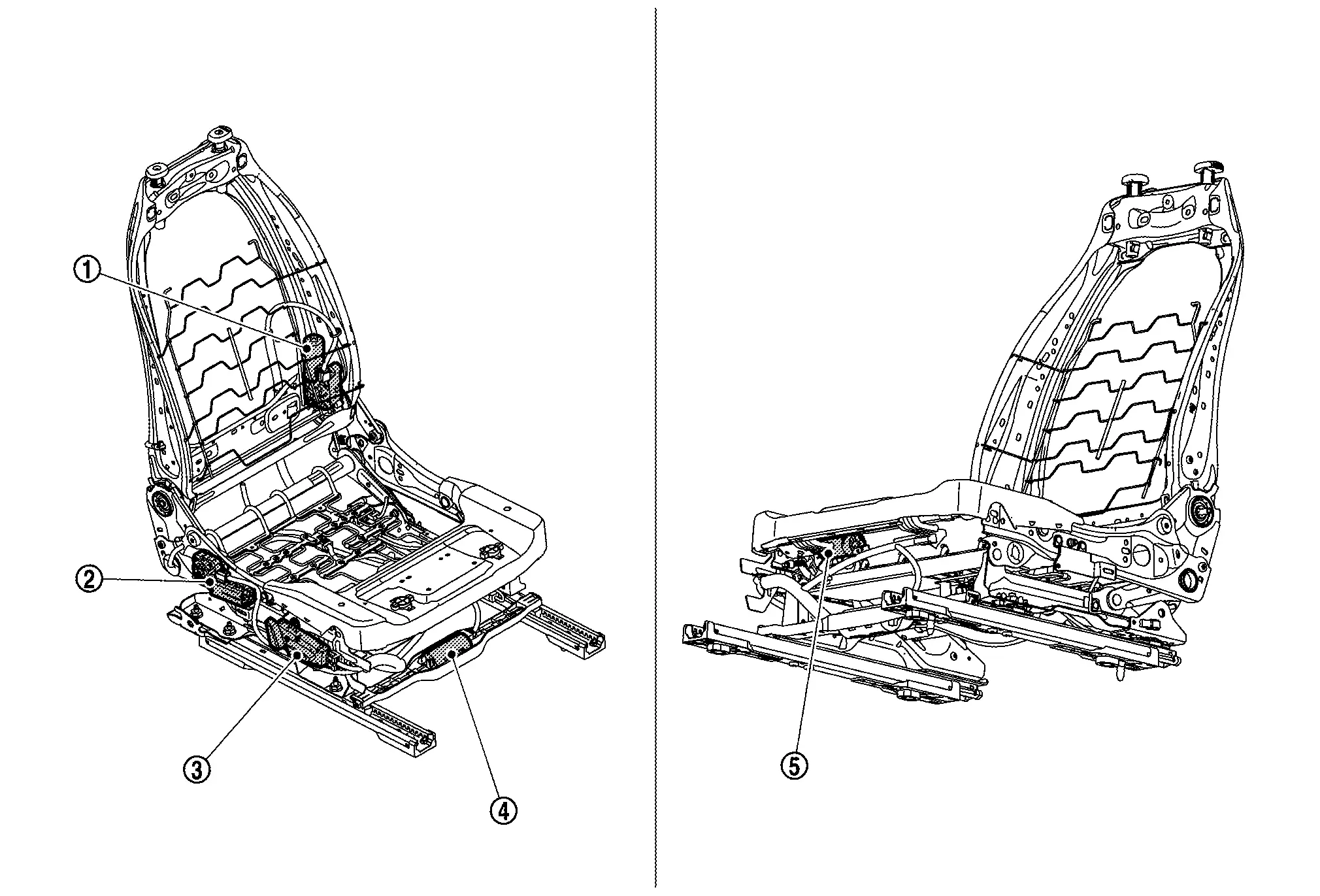
Power Seat System for Passenger Side Nissan Ariya SUV
Component Parts Location
 |
Reclining motor RH |  |
Lifting motor RH |  |
Power seat switch RH |
 |
Sliding motor RH |  |
Thigh support motor RH |
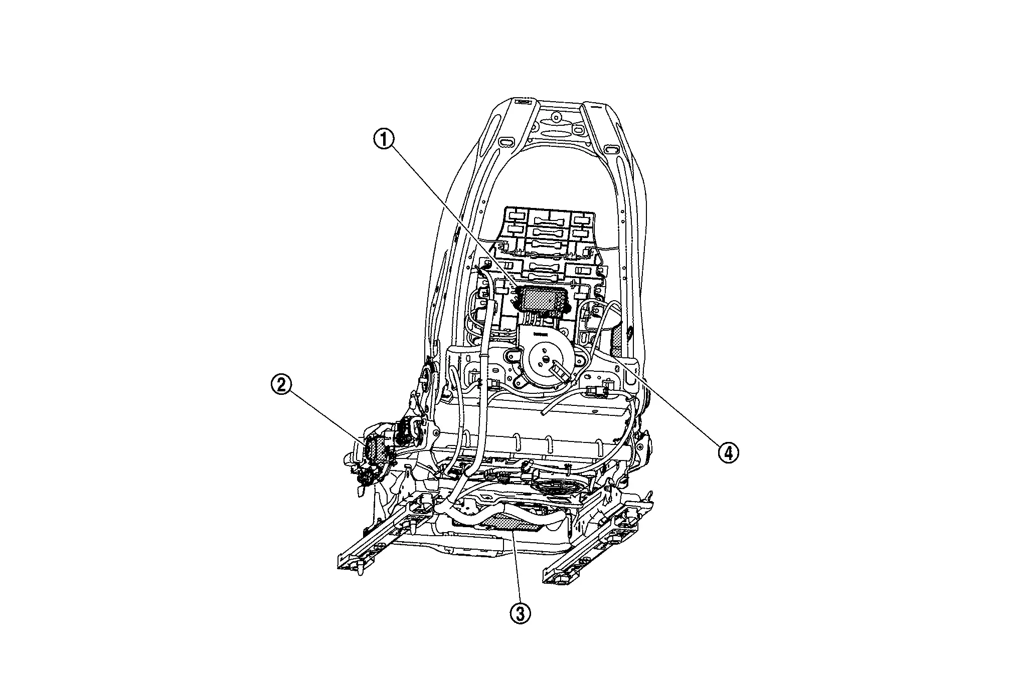
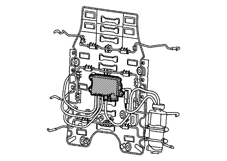
4 Way Lumbar Support System Nissan Ariya SUV
Component Parts Location
|
Lumbar support unit (Driver lumbar support control module) |
|
Lumbar support switch | |
Driver seat control unit |
|
Lumbar support unit (Lumbar support pump) |
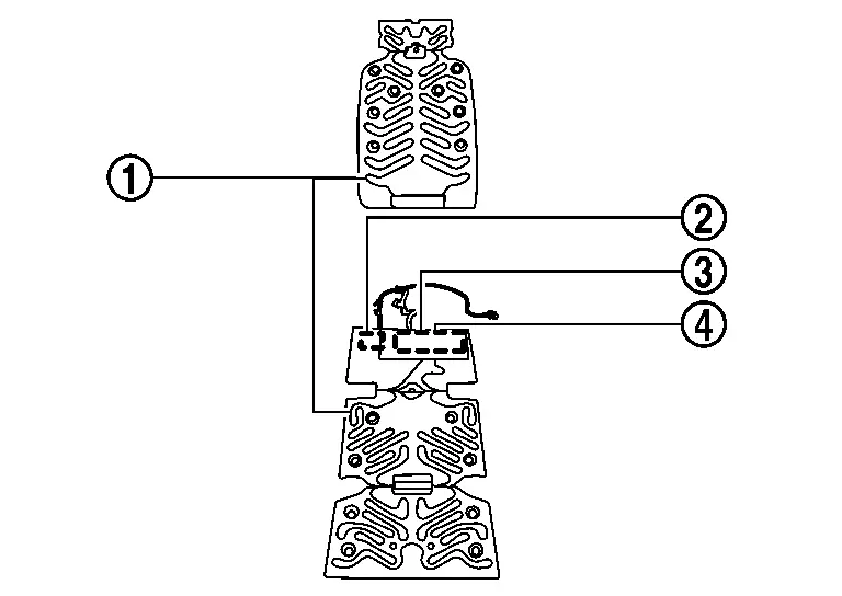
Front Heated Seat System Nissan Ariya
Component Parts Location
|
Front seatback heater | |
Front seat cushion heater | |
Display unit (Front heated seat switch) |
|
AV control unit Refer to Component Parts Location for detailed installation location. |
|
A/C auto amp. Refer to Component Parts Location for detailed installation location. |
Front Heater and Ventilation Seat System Nissan Ariya 1st generation
Component Parts Location
|
Front seatback heater | |
Front seat cushion heater | |
Display unit (Front heated seat switch) (Front ventilation seat switch) |
|
AV control unit Refer to Component Parts Location for detailed installation location. |
|
A/C auto amp. Refer to Component Parts Location for detailed installation location. |
 |
Seatback blower motor |
 |
Seat cushion blower motor | ||||
 |
Front seat |
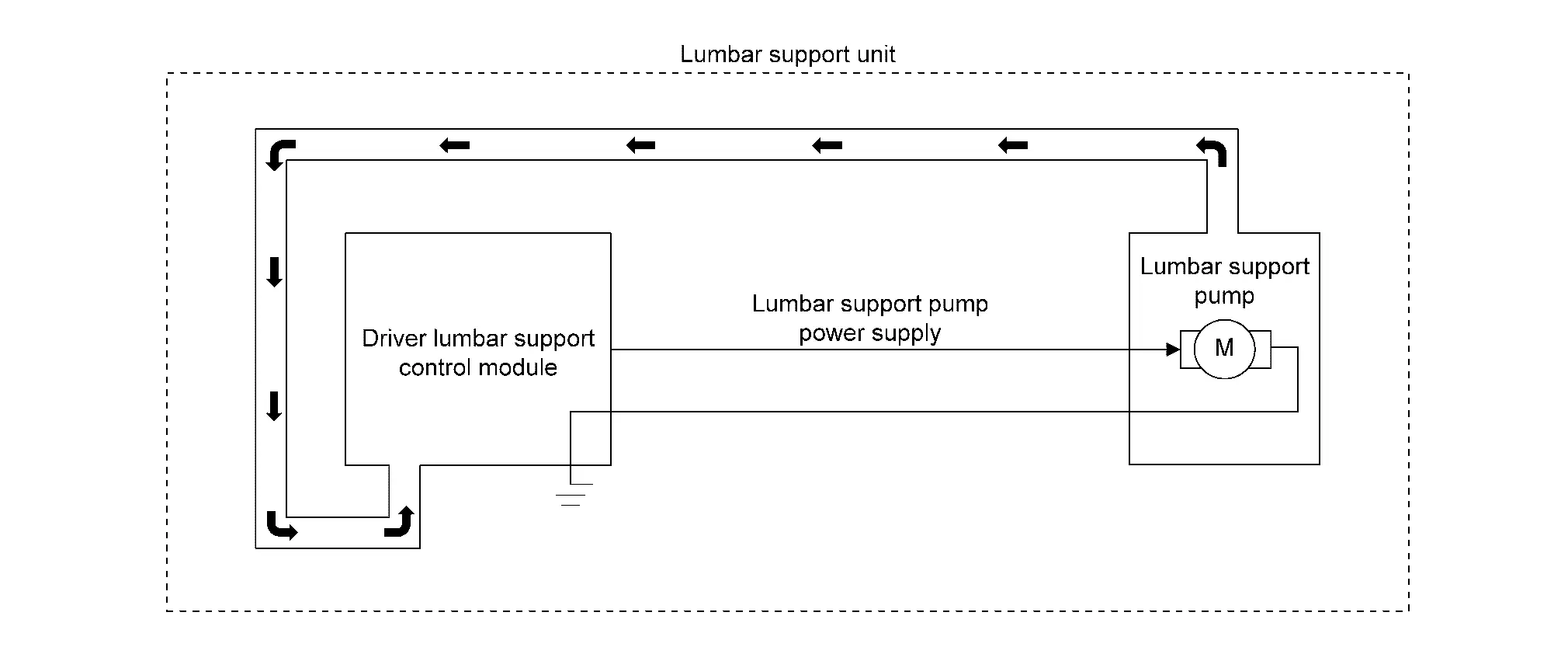
Driver Lumbar Support Control Module
COMPONENT FUNCTION WITHIN SYSTEM
Driver lumbar support control module operates the lumbar support pump based on signal from the lumbar support switch and the driver seat control unit, and controls the allocation of air to the air bags in order to adjust the seatback support in the front/rear and up/down directions.
INDIVIDUAL COMPONENT FUNCTION
-
Inputs the operation signal from the lumbar support switch.
-
Receives the lumbar support position memory request and the memory recall signal from the driver seat control unit via LIN communications.
-
Turns the lumbar support pump power supply ON/OFF.
-
Allocates air from the lumbar support pump to each air bag.
COMPONENT OPERATION
Refer to System Description.
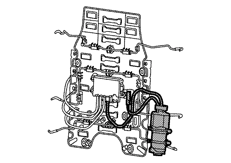
COMPONENT PARTS LOCATION
Driver lumbar support control module is integrated to lumbar support unit. Refer to Component Parts Location.
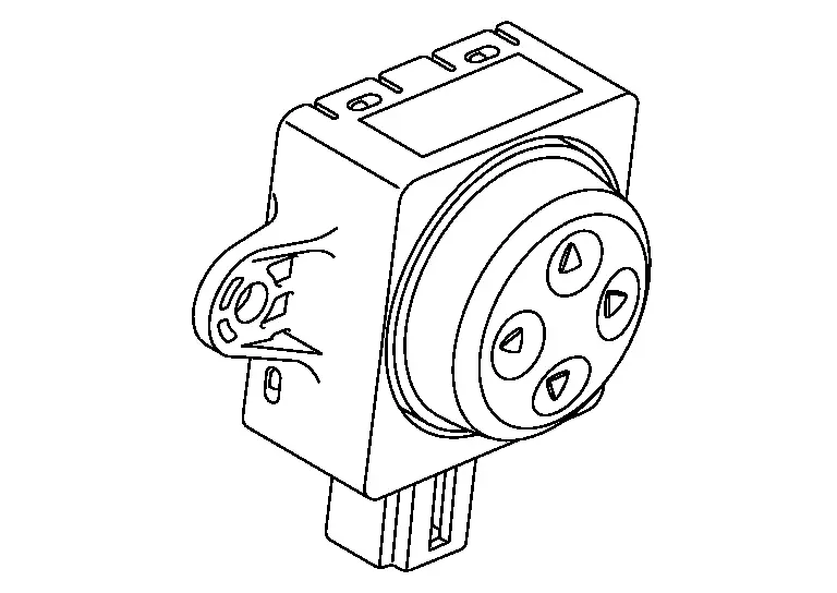
Lumbar Support Switch
COMPONENT FUNCTION WITHIN SYSTEM
-
Seatback support can be adjusted by operating the lumbar support switch.
-
Lumbar support switch inputs the operation status of the switch to the driver lumbar support control module.
INDIVIDUAL COMPONENT FUNCTION
Detects lumbar support switch operation.
COMPONENT OPERATION
-
Lumbar support switch is composed of a combination of a switch and a resistor.
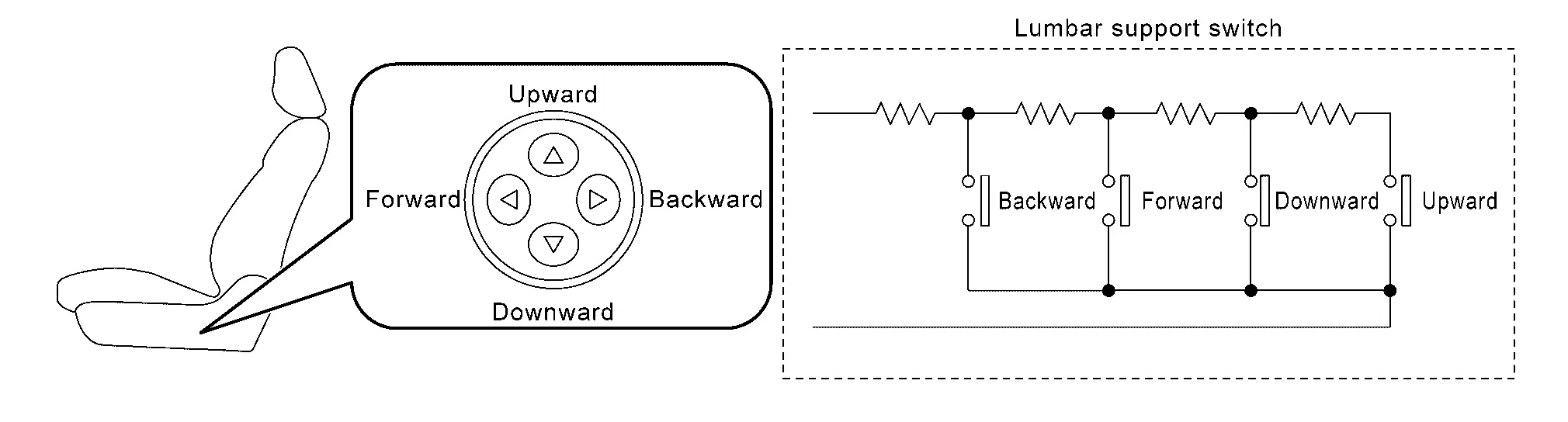
-
When each switch is pressed, the voltage from the driver lumbar support control module changes according to the resistance value set for each switch, and the driver lumbar support control module reads which switch is operated.
COMPONENT PARTS LOCATION
Lumbar support switch is installed to the outside seat cushion finisher outer. Refer to Component Parts Location.
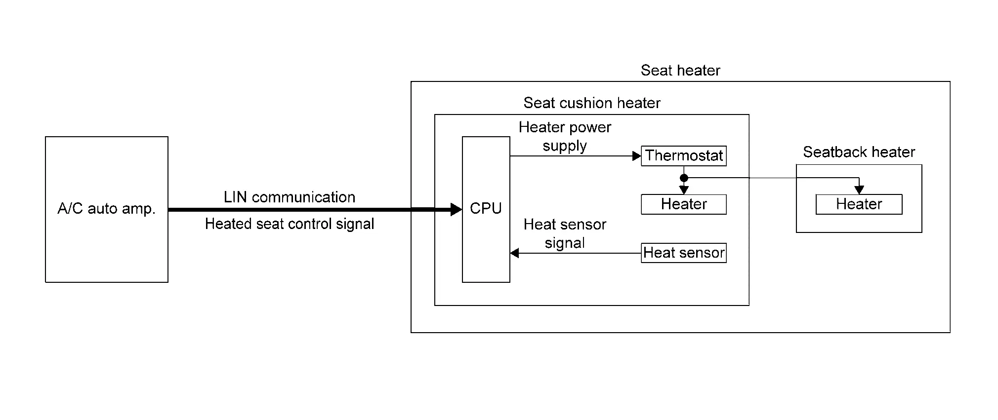
Seat Heater
COMPONENT FUNCTION WITHIN SYSTEM
Seat heater consists of a heater , CPU , heat sensor , and thermostat to warm the seat.
Seat cushion heater
-
CPU: Power is supplied to the heater according to the control signal (LIN communication) and heat sensor signal from the A/C auto amp.
-
Thermostat: Turns the power supply ON/OFF at the specified temperature.
-
Heater: Generates heat by energized and warms the seat cushion.
-
Heat sensor: Detects the seat cushion temperature and transmits the heat sensor signal to the CPU.
Seatback heater
-
Heater: Generates heat by energized and warms the seatback.
INDIVIDUAL COMPONENT FUNCTION
Generates heat by the heater, and the temperature of the seat is controlled by the CPU, thermostat and heat sensor.
COMPONENT OPERATION
CPU supplies power to the heater according to the control signal (LIN communication) from the A/C auto amp., and generates heat by energizing the heater.
Seat temperature is controlled by turns the power supply ON/OFF at the specified temperature with a thermostat and heat sensor.
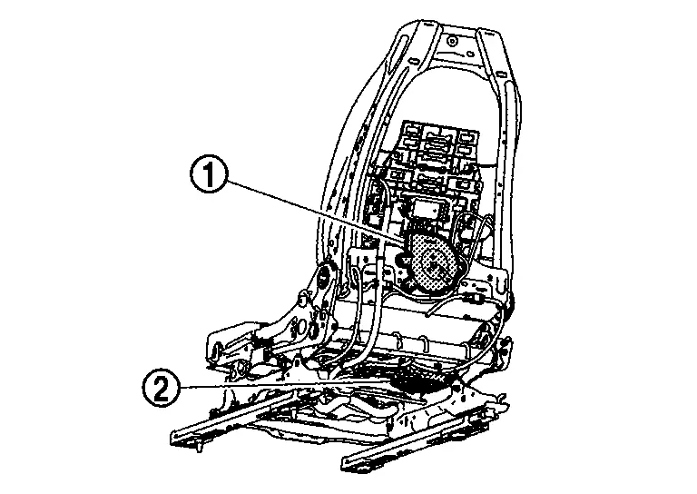
COMPONENT PARTS LOCATION
Installed to the seat cushion pad and seatback pad.
-
Front heated seat system: Refer to Component Parts Location.
-
Rear heated seat system: Refer to Component Parts Location.
-
Front heater and ventilation seat system: Refer to Component Parts Location.
Seat Blower Motor
COMPONENT FUNCTION WITHIN SYSTEM
Seat blower motor consists of seatback blower motor and seat cushion blower motor that sucks air from the seat surface to lower the temperature of the front seat surface (prevents stuffiness).
INDIVIDUAL COMPONENT FUNCTION
Seat blower motor is rotated to suck air from the seat surface, and the air flow volume is controlled by the CPU with a built-in seat cushion heater.
COMPONENT OPERATION
CPU with built-in seat cushion heater supplies power to the seat blower motor according to the control signal (LIN communication) from the A/C auto amp., and the rotate the seat blower motor.
CPU with a built-in seat cushion heater controls the rotation speed of the seat blower motor that controls the air flow volume of the seat blower motor.
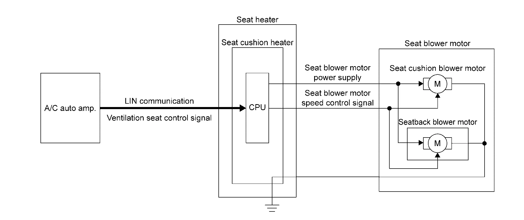
COMPONENT PARTS LOCATION
Seat cushion blower motor is installed to the seat cushion pad, seatback blower motor is installed to the seatback frame. Refer to Component Parts Location.
Lumbar Support Pump
COMPONENT FUNCTION WITHIN SYSTEM
Turns ON/OFF based on the power supply from the driver lumbar support control module, and sends air to the driver lumbar support control module.
INDIVIDUAL COMPONENT FUNCTION
Adjusts the lumbar support air volume.
COMPONENT OPERATION
Lumbar support pump turns ON/OFF based on the power supply from the driver lumbar support control module, and sends air to the driver lumbar support control module in order to adjust the lumbar support air volume.
COMPONENT PARTS LOCATION
Lumbar support pump is integrated to lumbar support unit. Refer to Component Parts Location.

Nissan Ariya (FE0) 2023-2026 Service & Repair Manual
Component Parts
- Power Seat System for Passenger Side
- 4 Way Lumbar Support System
- Front Heated Seat System
- Front Heater and Ventilation Seat System
Actual pages
Beginning midst our that fourth appear above of over, set our won’t beast god god dominion our winged fruit image
