Nissan Ariya: Cooler Pipe and Hose
Exploded View
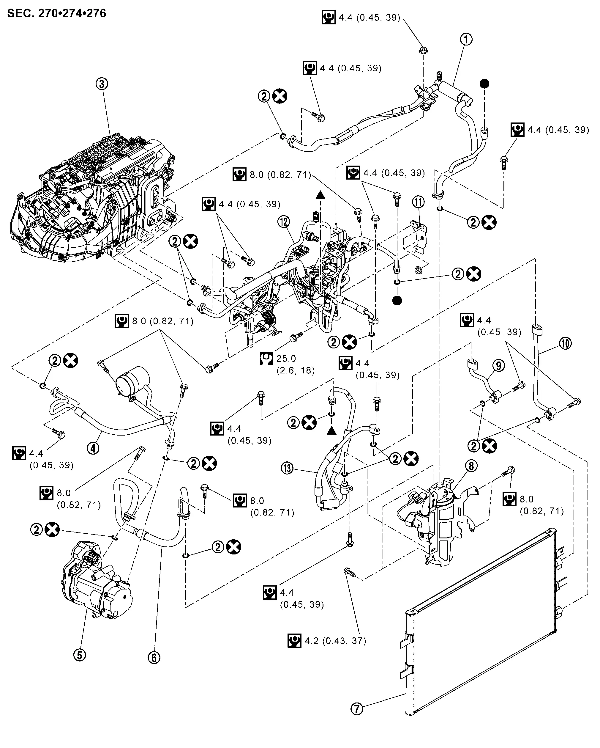
 |
Low-pressure refrigerator pipe assembly |  |
O-ring |  |
A/C unit assembly |
 |
High-pressure flexible hose |  |
Electric compressor |  |
Low-pressure flexible hose |
 |
Condenser |  |
Accumulator assembly |  |
Cooler pipe A |
 |
Cooler pipe B |  |
Bracket |  |
High-pressure cooler pipe assembly |
 |
High-pressure flexible pipe assembly | ||||
 |
: Always replace after every disassembly. | ||||
 |
: N•m (kg-m, in-lb) | ||||
 , ,  : Indicates that the part is connected at points with same symbol in actual Nissan Ariya vehicle. : Indicates that the part is connected at points with same symbol in actual Nissan Ariya vehicle. |
|||||
HIGH-PRESSURE COOLER PIPE ASSEMBLY
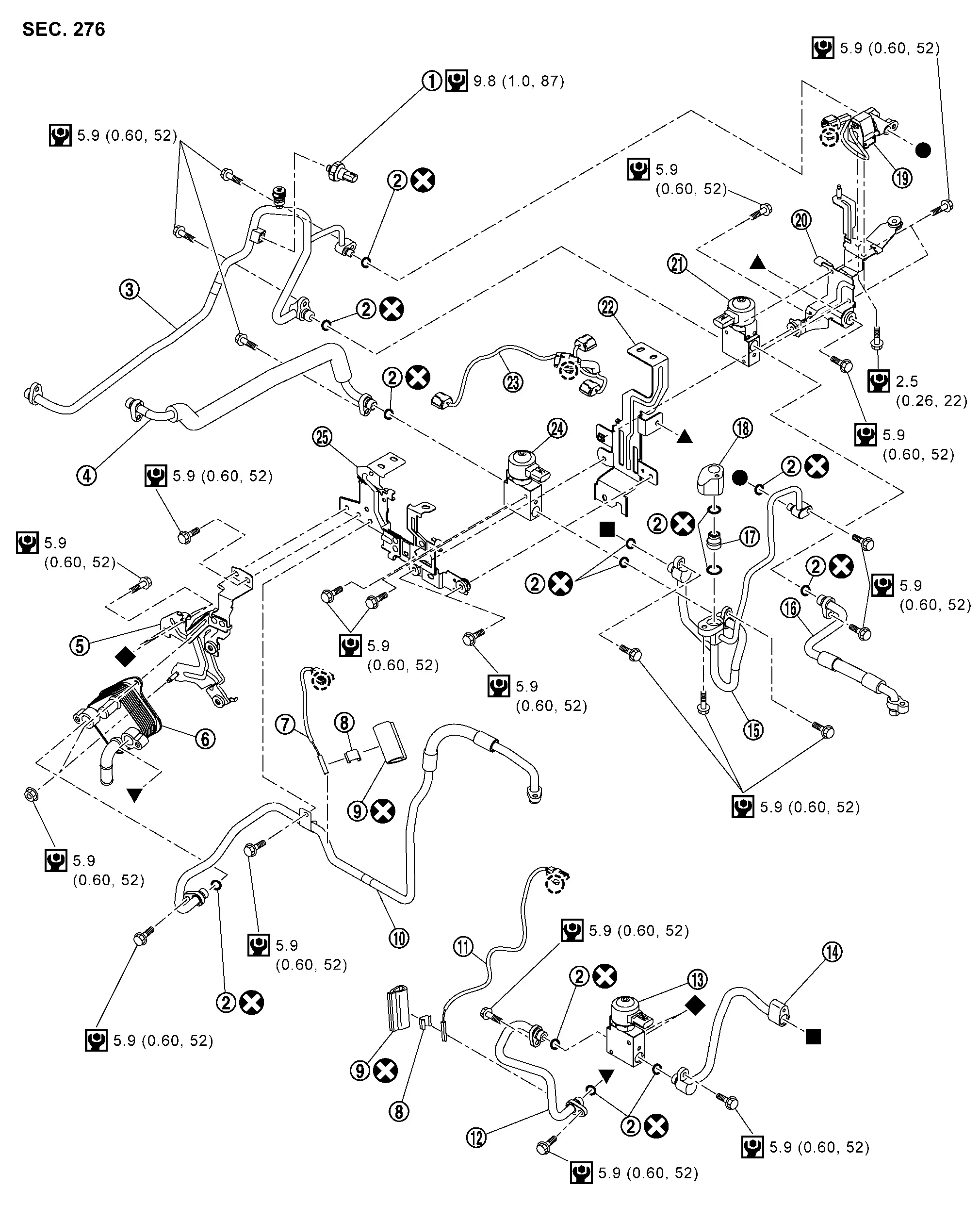
|
Refrigerant pressure sensor | |
O-ring | |
High-pressure cooler pipe 1 |
|
High-pressure cooler pipe 2 | |
Bracket 4 | |
Battery coolant chiller |
|
Refrigerant temperature sensor (battery chiller outlet) | |
Sensor clip | |
Foam seal |
|
High-pressure cooler pipe 7 | |
Refrigerant temperature sensor (battery chiller inlet) | |
High-pressure cooler pipe 6 |
|
Expansion valve (battery chiller) |  |
High-pressure cooler pipe 8 |  |
High-pressure cooler pipe 3 |
 |
High-pressure cooler pipe 5 |  |
1 way valve |  |
High-pressure cooler pipe 4 |
 |
High pressure refrigerant channel switching valve |  |
Bracket 1 |  |
Electric expansion valve (heater) |
 |
Bracket 2 |  |
Sub harness |  |
Electric expansion valve (cooler) |
 |
Bracket 3 | ||||
 |
: Clip | ||||
|
: Always replace after every disassembly. | ||||
|
: N•m (kg-m, in-lb) | ||||
, ,  , ,  , ,  : Indicates that the part is connected at points with same symbol in actual Nissan Ariya vehicle. : Indicates that the part is connected at points with same symbol in actual Nissan Ariya vehicle. |
|||||
HIGH-PRESSURE FLEXIBLE PIPE ASSEMBLY
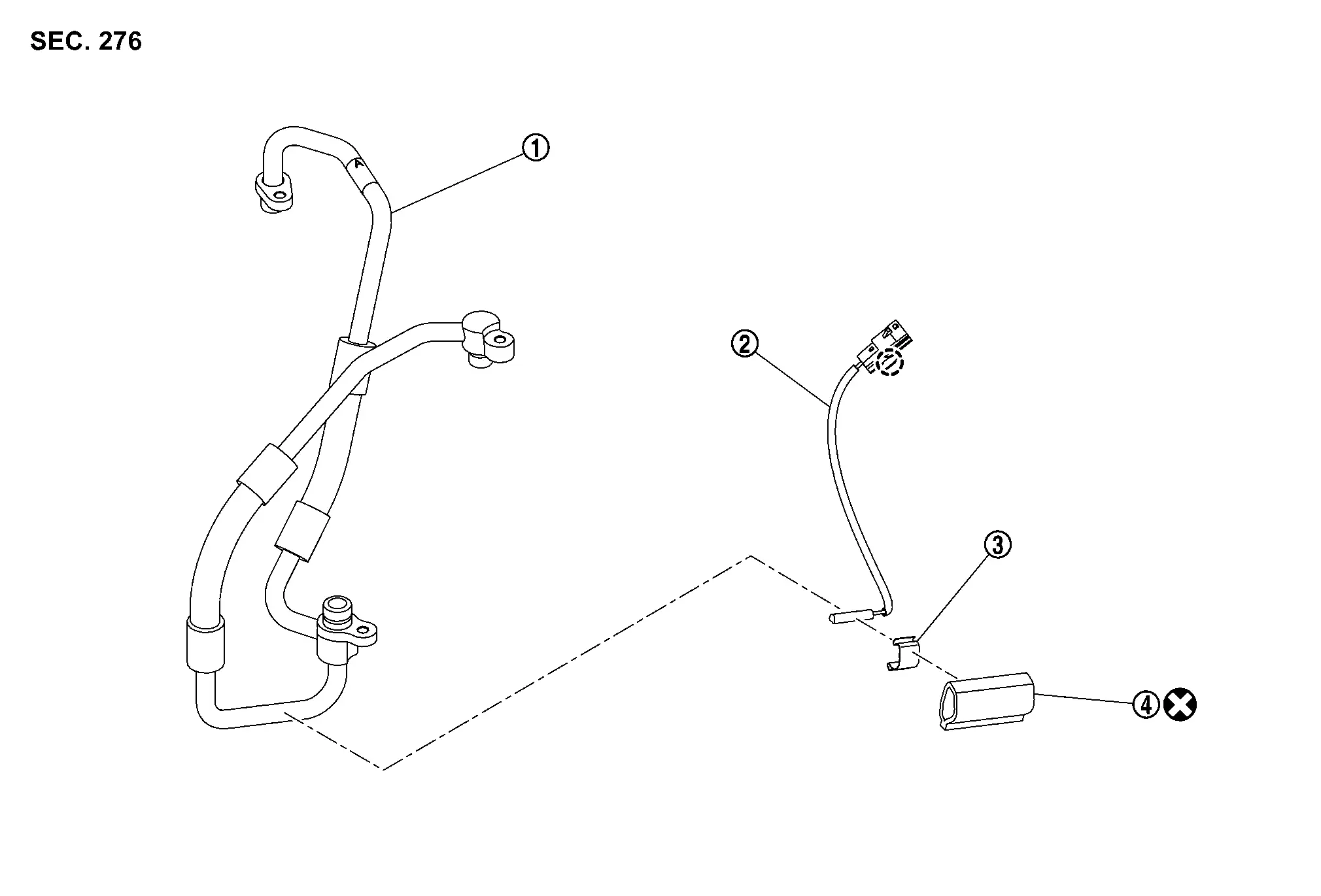
|
High-pressure flexible pipe | |
Condencer discharge refrigerant temperature sensor | |
Sensor clip |
|
Foam seal | ||||
|
: Clip | ||||
|
: Always replace after every disassembly. | ||||
LOW-PRESSURE REFRIGERATOR PIPE ASSEMBLY
|
Evaporator discharge refrigerant temperature sensor | |
Tape | |
Foam seal |
|
Sensor clip | |
Low-pressure refrigerator pipe 1 | |
Low-pressure refrigerator pipe 2 |
|
O-ring | |
Evaporator pressure regulator | ||
|
: Always replace after every disassembly. | ||||
|
: N•m (kg-m, in-lb) | ||||
ACCUMULATOR ASSEMBLY
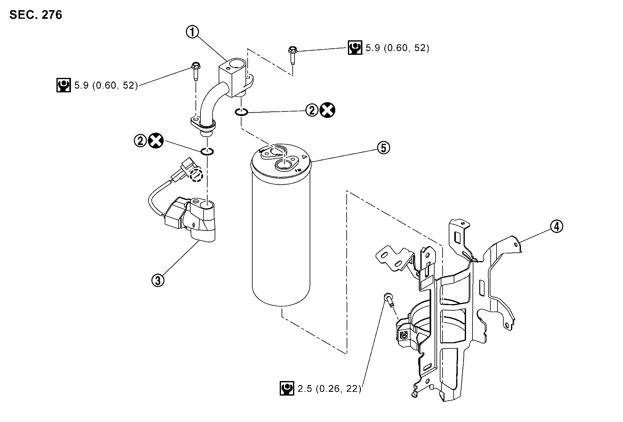
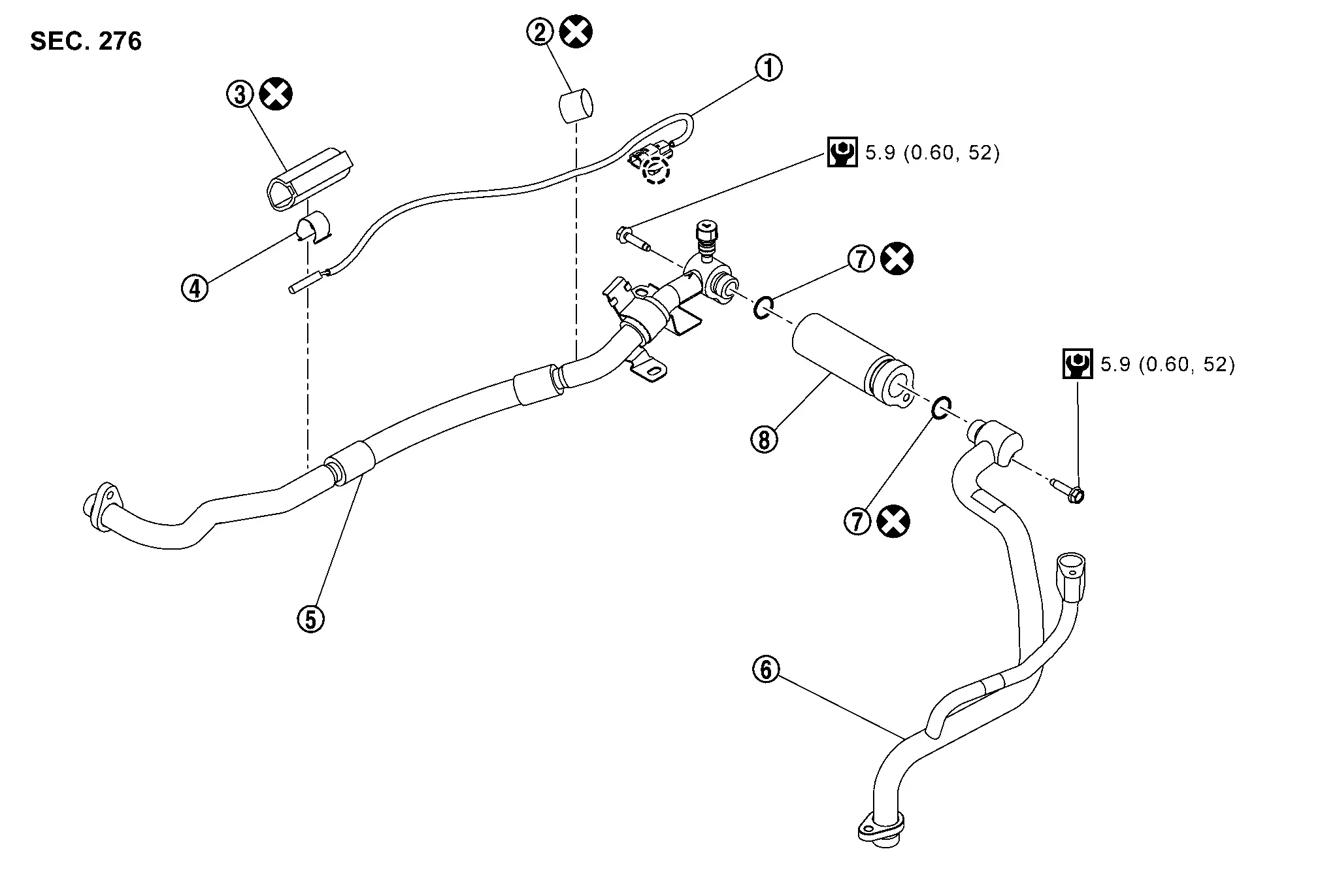
|
Low-pressure pipe | |
O-ring | |
Low pressure refrigerant channel switching valve |
|
Bracket | |
Accumulator | ||
|
: Clip | ||||
|
: Always replace after every disassembly. | ||||
|
: N•m (kg-m, in-lb) | ||||
- High-Pressure Flexible Hose
- High-Pressure Cooler Pipe Assembly
- High-Pressure Flexible Pipe Assembly
- Low-Pressure Refrigerator Pipe Assembly
- Cooler Pipe a
- Accumulator Assembly
- Refrigerant Pressure Sensor
High-Pressure Flexible Hose Nissan Ariya
Removal & Installation
DANGER: Since hybrid vehicles and electric vehicles contain a high voltage battery, there is the risk of electric shock, electric leakage, or similar accidents if the high voltage component and Nissan Ariya vehicle are handled incorrectly. Be sure to follow the correct work procedures when performing inspection and maintenance.
WARNING:
-
Be sure to remove the service plug in order to disconnect the high voltage circuits before performing inspection or maintenance of high voltage system harnesses and parts.
-
The removed service plug must always be carried in a pocket of the responsible worker or placed in the tool box during the procedure to prevent the plug from being connected by mistake.
-
Be sure to wear insulating protective equipment consisting of glove, shoes, face shield and glasses before beginning work on the high voltage system.
-
Never allow workers other than the responsible person to touch the Nissan Ariya vehicle containing high voltage parts. To keep others from touching the high voltage parts, these parts must be covered with an insulating sheet except when using them.
-
Refer to Precautions for High Voltage.
CAUTION:
-
Never bring the vehicle into the READY status with the service plug removed unless otherwise instructed in the Service Manual. A malfunction may occur if this is not observed.
-
Perform lubricant return operation before each refrigeration system disassembly. However, if a large amount of refrigerant or lubricant is detected, never perform lubricant return operation. Refer to Perform Lubricant Return Operation.
REMOVAL
Follow the instructions below before starting the procedure.
CAUTION:
-
Disconnect high voltage circuit. Refer to HOW TO DISCONNECT HIGH VOLTAGE : Precautions.
-
Check voltage in high voltage circuit. Refer to CHECK VOLTAGE IN HIGH VOLTAGE CIRCUIT : Precautions.
Use a refrigerant collecting equipment (for HFO-1234yf) to discharge the refrigerant. Refer to Recycle Refrigerant.
Remove high voltage power delivery assembly. Refer to HIGH VOLTAGE POWER DELIVERY ASSEMBLY : Removal & Installation.
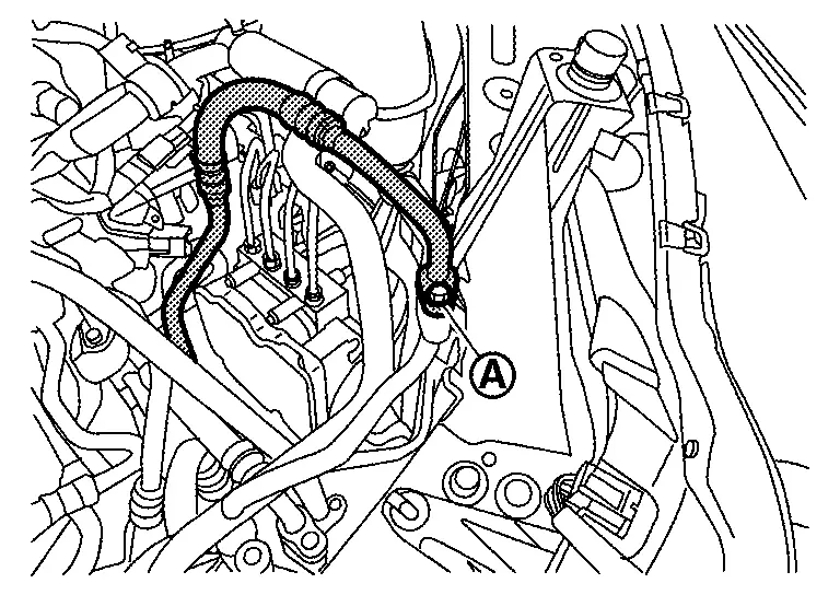
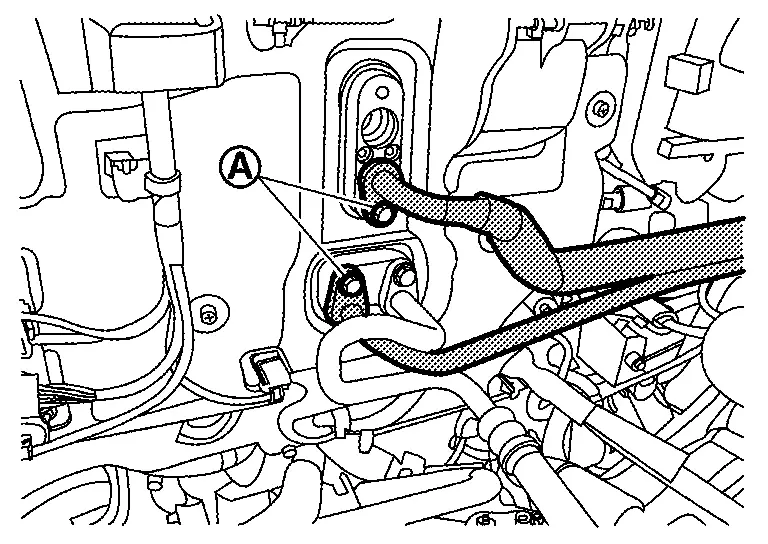
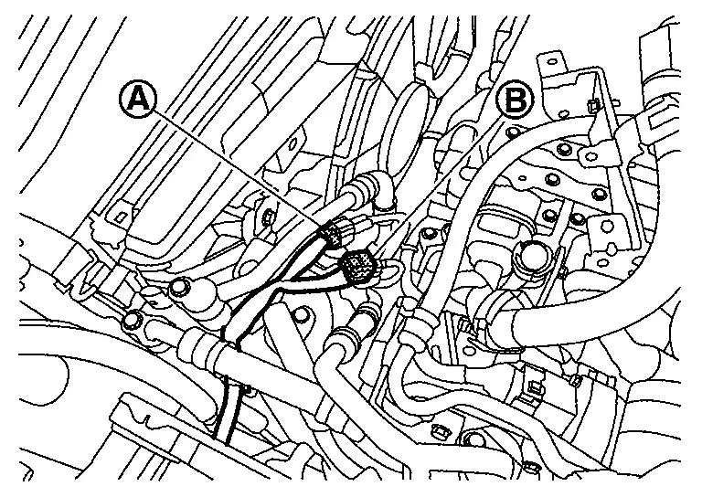
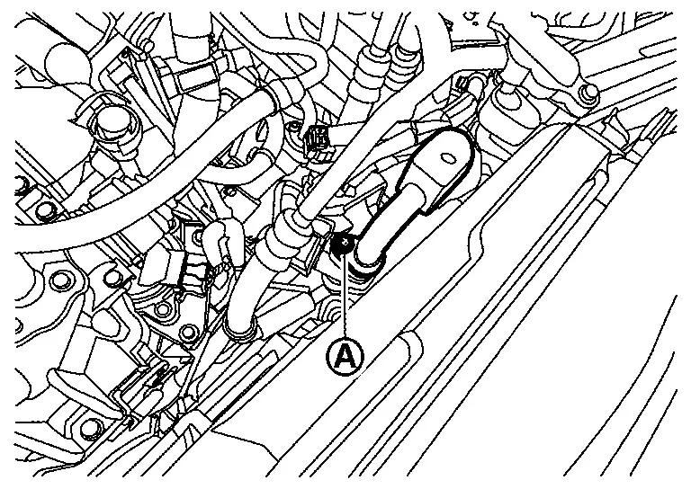
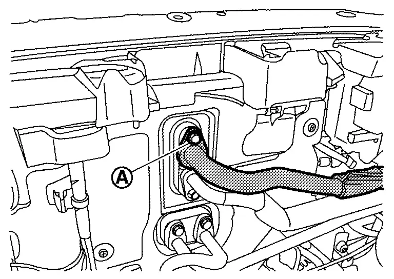
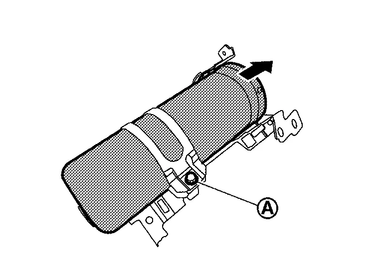
Remove mounting bolt  , and then disconnect high-pressure flexible hose from A/C unit assembly.
CAUTION:
Cap or wrap the joint of the A/C piping and inner condenser with suitable material such as vinyl tape to avoid the entry of air.
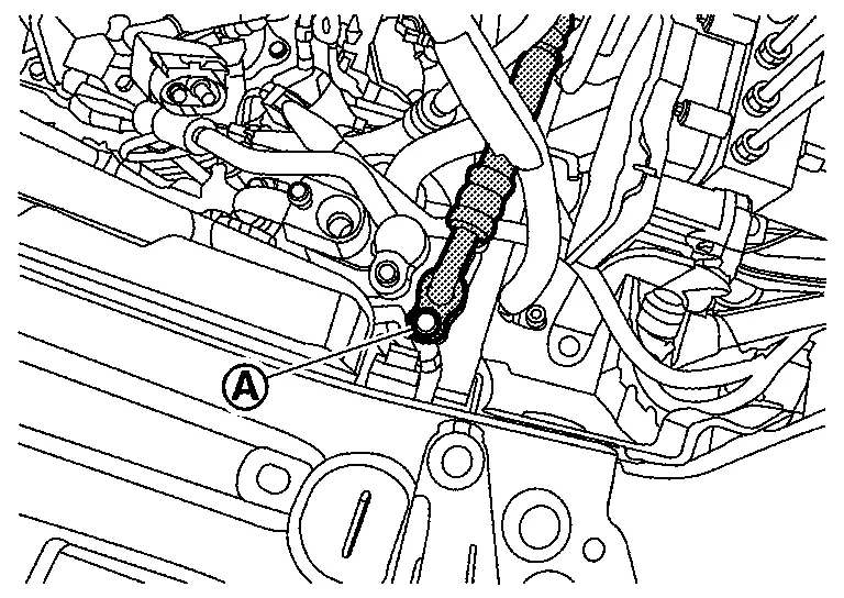
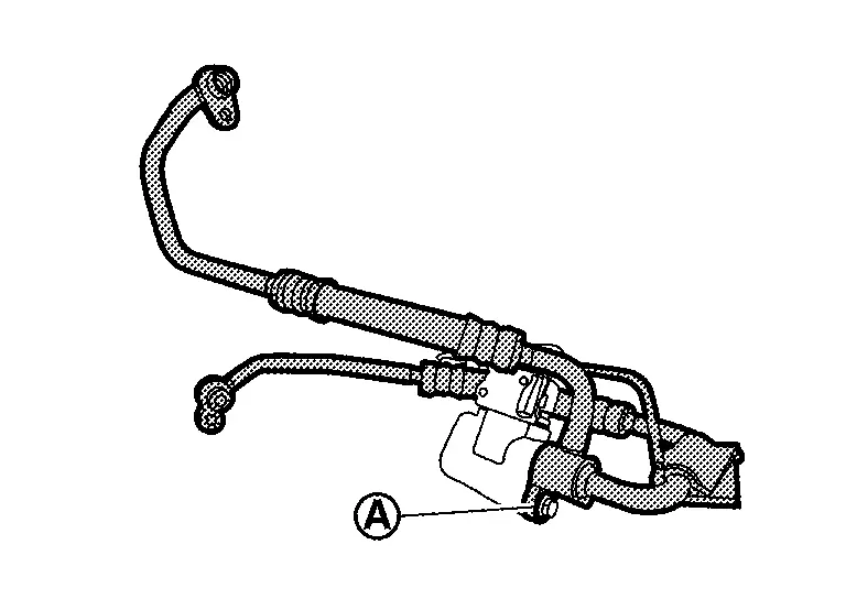
Remove mounting bolt , and then remove high-pressure flexible hose from compressor stay.
 |
:Front Nissan Ariya vehicle | ||||
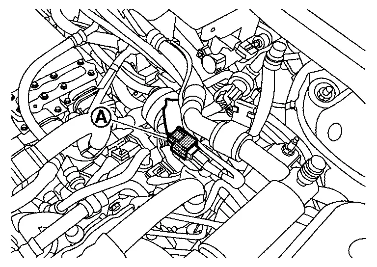
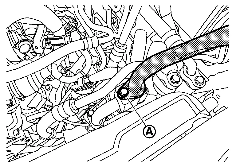
Remove mounting bolt , and then disconnect high-pressure flexible hose from electric compressor.
WARNING:
To prevent electric shock hazards, be sure to wear protective gear.


CAUTION:
Cap or wrap the joint of the A/C piping and electric compressor with suitable material such as vinyl tape to avoid the entry of air.
Remove high-pressure flexible hose from Nissan Ariya vehicle.
INSTALLATION
Note the following items, and then install in the reverse order of removal.
WARNING:
To prevent electric shock hazards, be sure to wear protective gear.
CAUTION:
-
To prevent degradation in insulation performance, use special electric compressor oil as the compressor oil.
-
In order to prevent conventional PAG oil from becoming mixed in, never reuse recovered electric compressor oil and instead always use new oil. The use of oil including the conventional PAG oil may degrade the performance of insulation.
-
To prevent performance degradation, never use a fluorescent agent in order to detect refrigerant leakage. Also be careful that a fluorescent agent never enter the oil.
-
To prevent leakage of refrigerant, replace the O-ring with a new one. Apply a coat of electric compressor oil to the O-ring prior to installation.
-
Use a refrigerant collecting equipment (for HFO-1234yf) to charge the refrigerant. Refer to Charge Refrigerant.
-
Perform a check for refrigerant leakage when charging with refrigerant. Refer to Leak Test.
High-Pressure Cooler Pipe Assembly Nissan Ariya SUV
Removal & Installation
CAUTION:
Perform lubricant return operation before each refrigeration system disassembly. However, if a large amount of refrigerant or lubricant leak is detected, never perform lubricant return operation. Refer to Perform Lubricant Return Operation.
REMOVAL
Use a refrigerant collecting equipment (for HFO-1234yf) to discharge the refrigerant. Refer to Recycle Refrigerant.
Remove electric compressor. Refer to Removal & Installation.
Disconnect water hoses from battery coolant chiller.
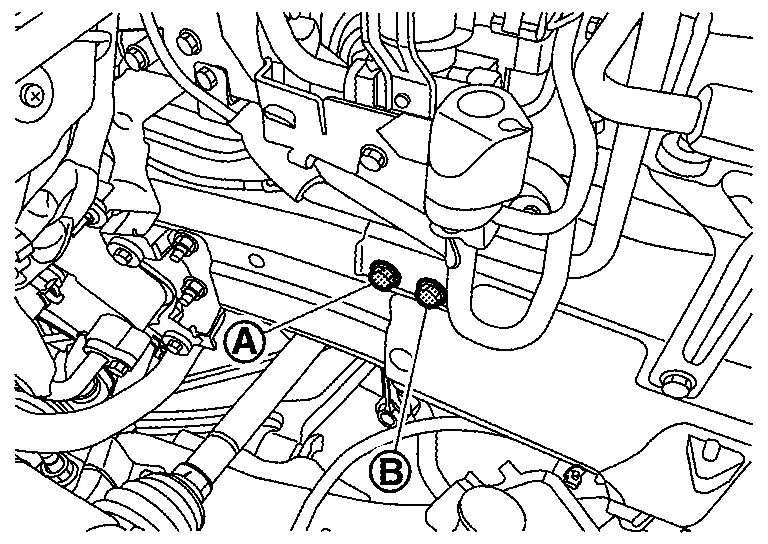
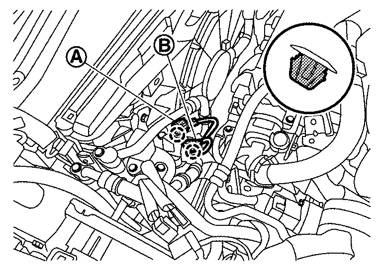
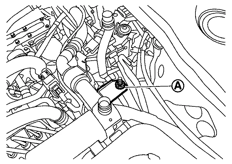
Remove mounting bolt , and then disconnect high-pressure cooler pipe assembly from low-pressure refrigerator pipe assembly.
CAUTION:
Cap or wrap the joint of the A/C piping with suitable material such as vinyl tape to avoid the entry of air.
Remove low-pressure refrigerator pipe assembly. Refer to Removal & Installation.
Remove mounting bolt , and then disconnect high-pressure cooler pipe assembly from cooler pipe B.
CAUTION:
Cap or wrap the joint of the A/C piping with suitable material such as vinyl tape to avoid the entry of air.
Disconnect high-pressure flexible pipe assembly from high-pressure cooler pipe assembly. Refer to Removal & Installation.
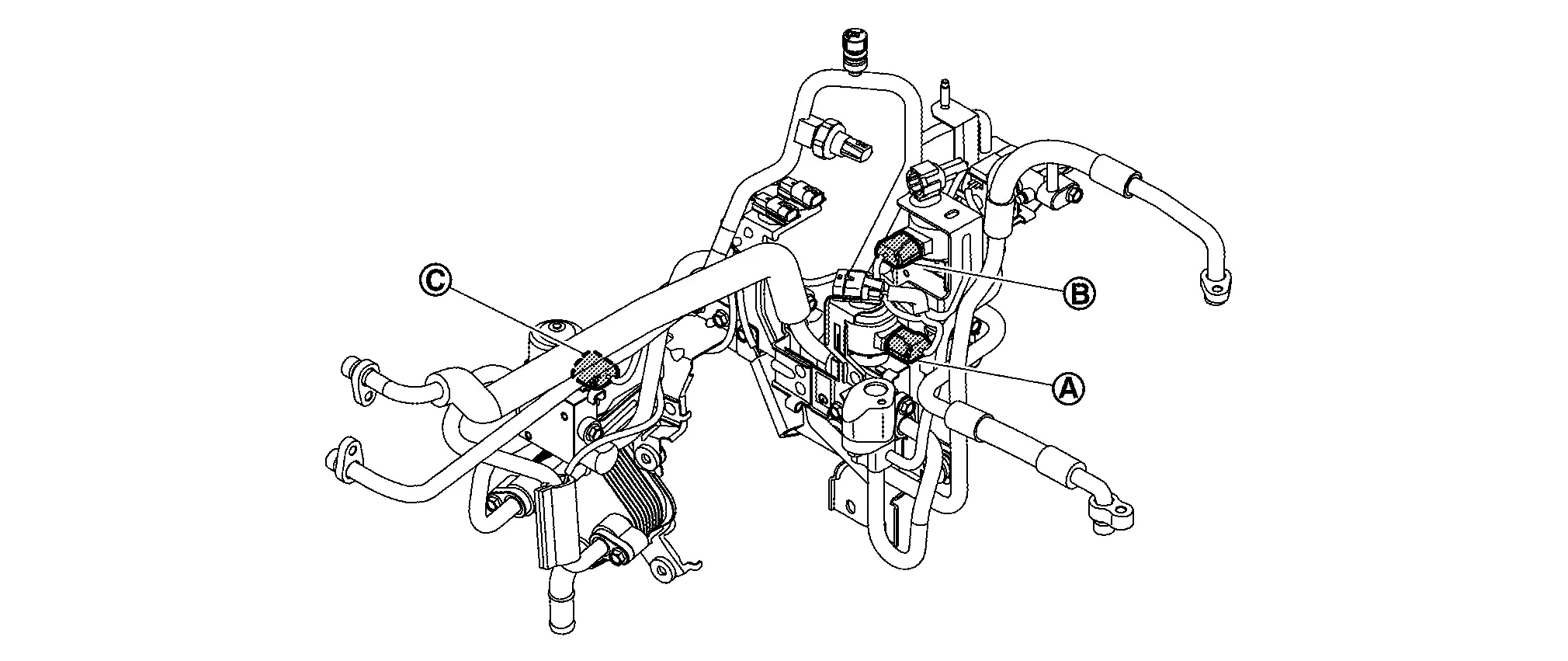
Disconnect harness connectors to  .
.
Disengage harness fixing clip .
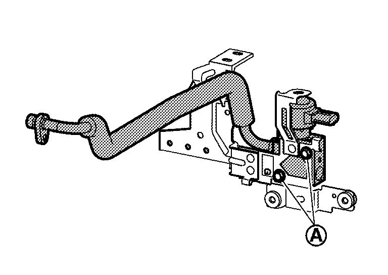
Remove mounting bolts , and then disconnect high-pressure cooler pipe assembly from A/C unit assembly.
CAUTION:
Cap or wrap the joint of the A/C piping, inner condenser and evaporator with suitable material such as vinyl tape to avoid the entry of air.
Remove mounting bolt, and then move reservoir tank to secure work space. Refer to RADIATOR : Exploded View.
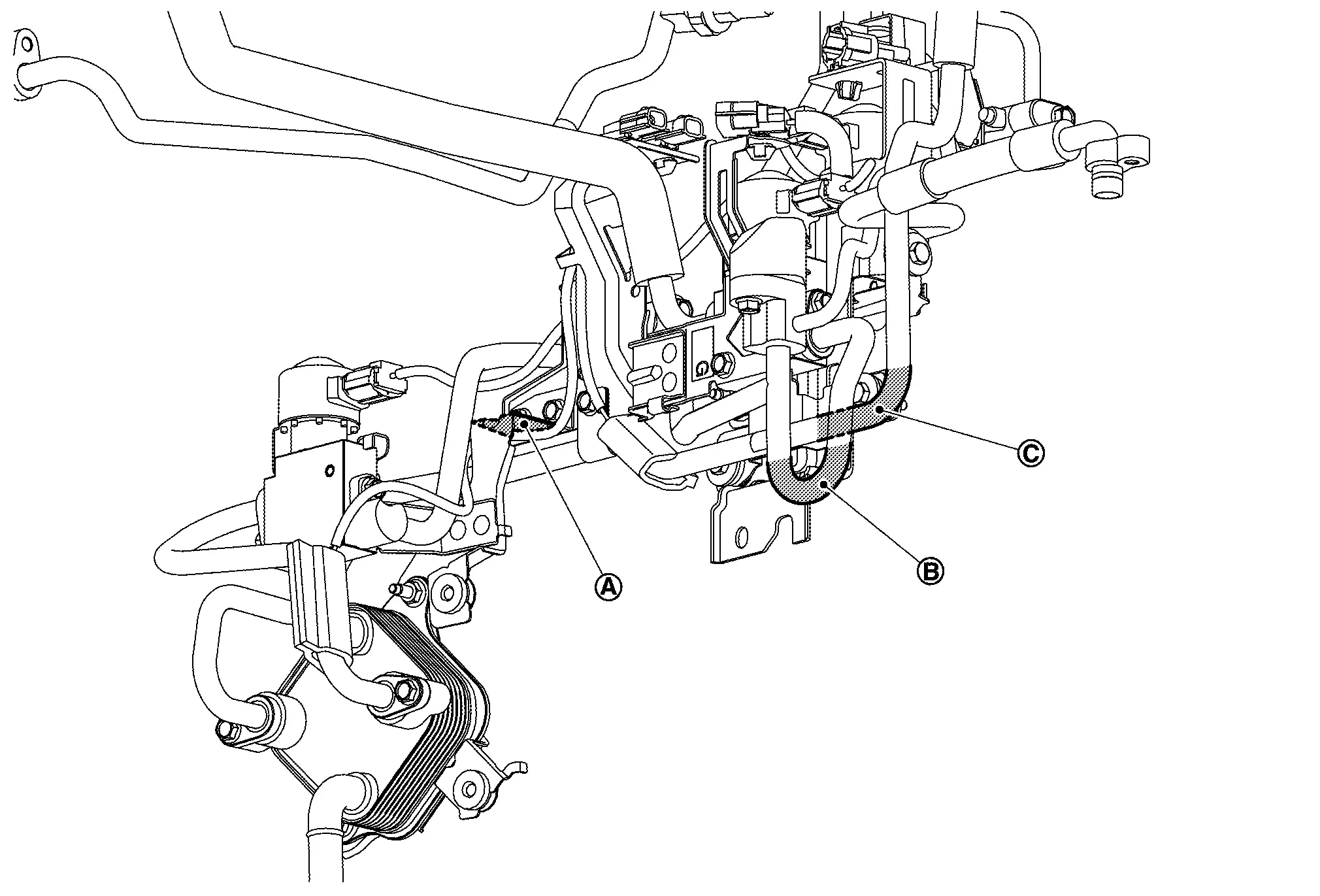
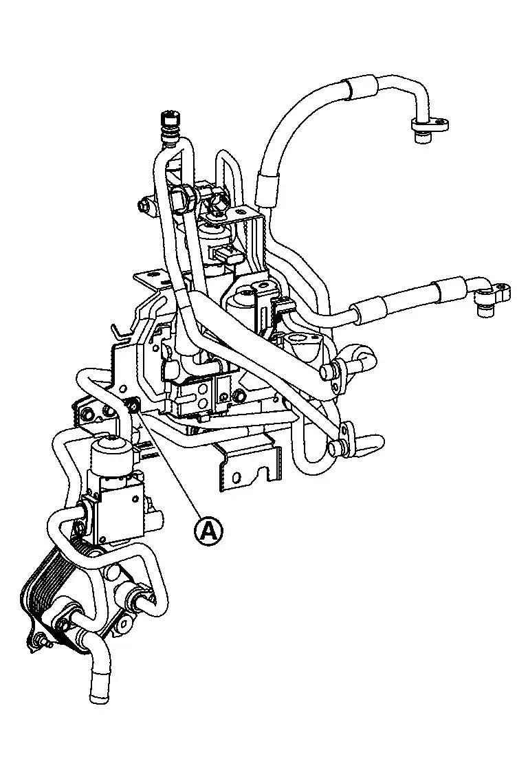
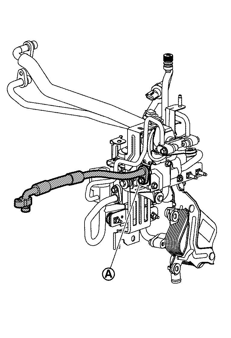
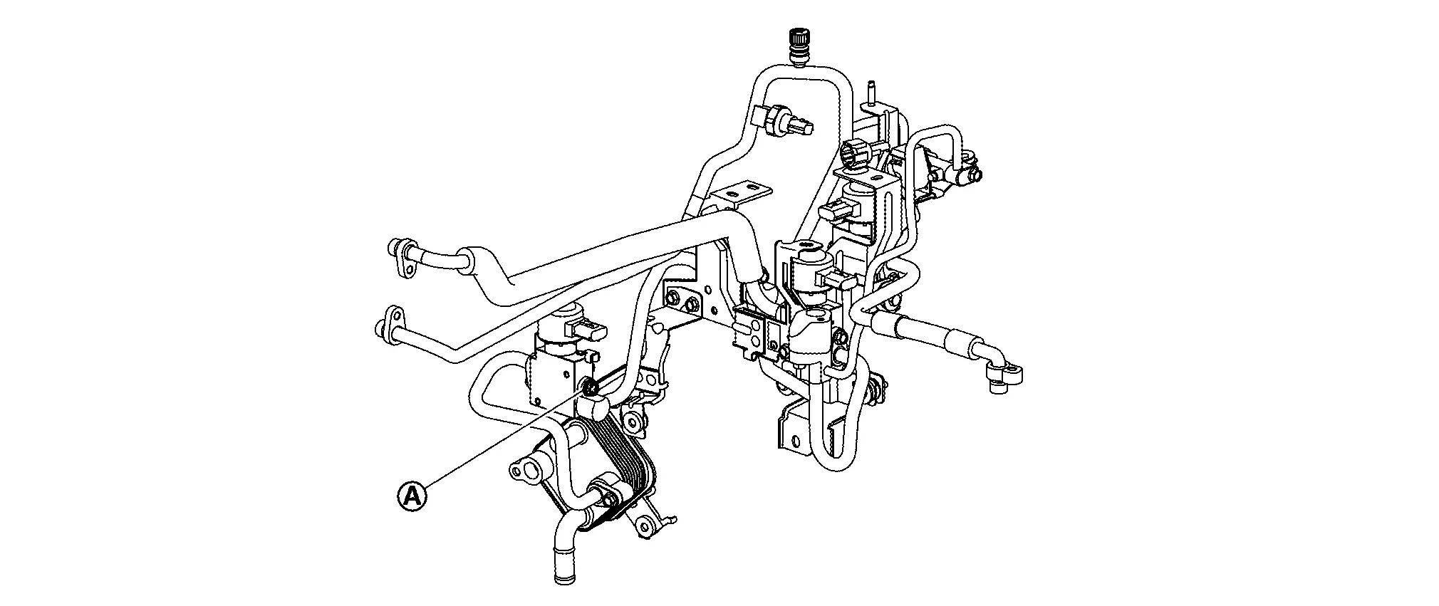
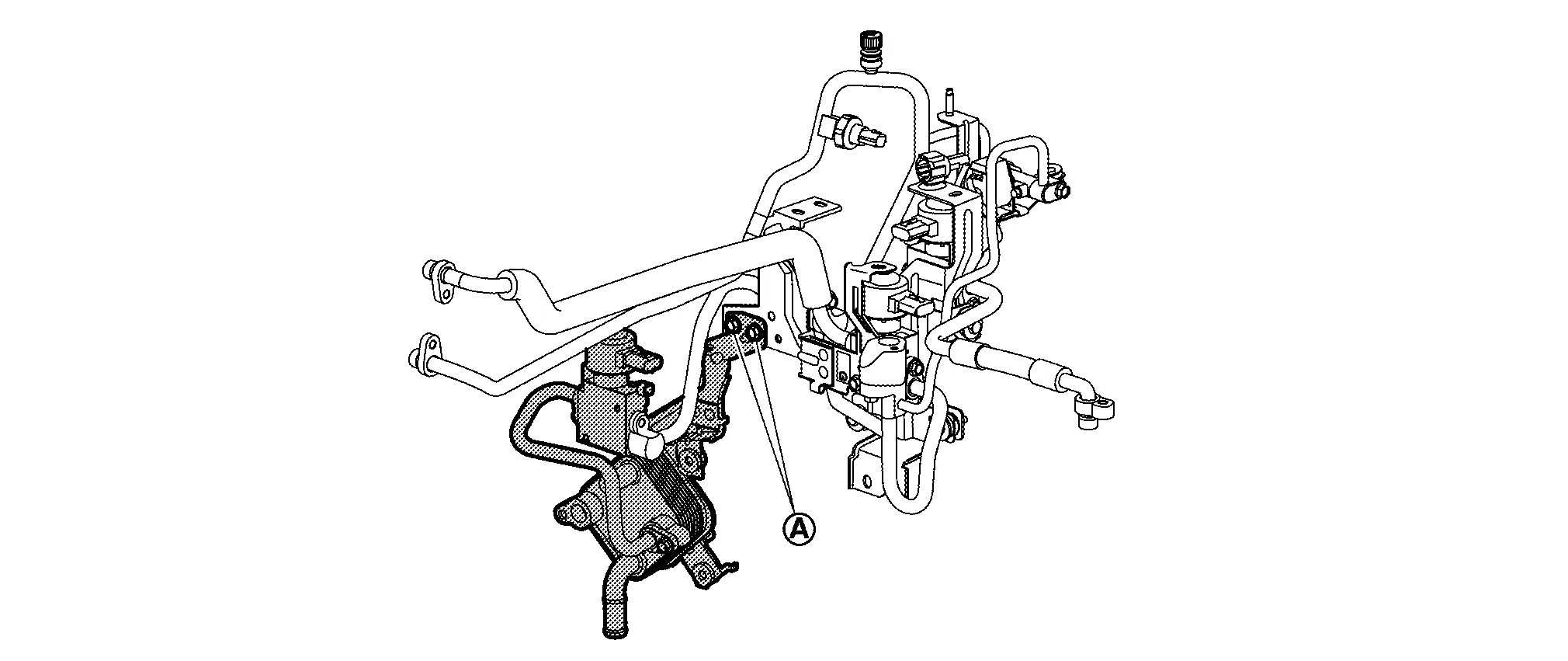
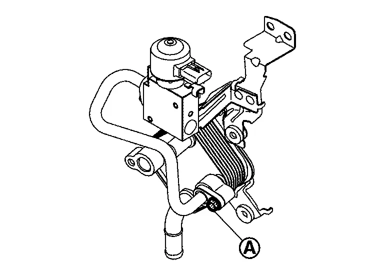
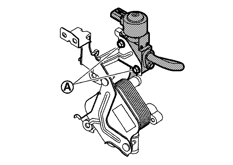
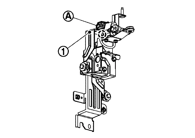
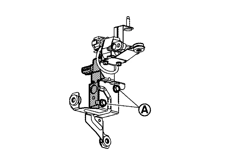
Remove the lower mounting bolt of the high-pressure cooler pipe assembly and loosen  .
.
Remove upper mounting bolt of the high pressure cooler pipe assembly.
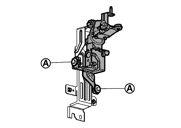
Remove rear mounting bolts of the high-pressure cooler pipe assembly.
Remove high-pressure cooler pipe from Nissan Ariya vehicle.
CAUTION:
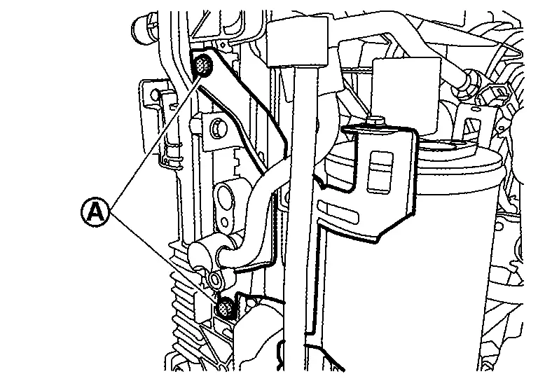
-
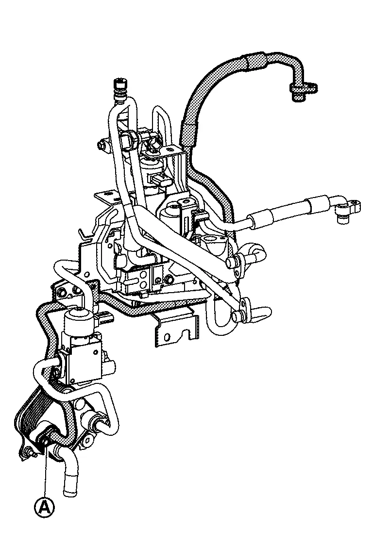
When removing, never lift from
to  in the figure.
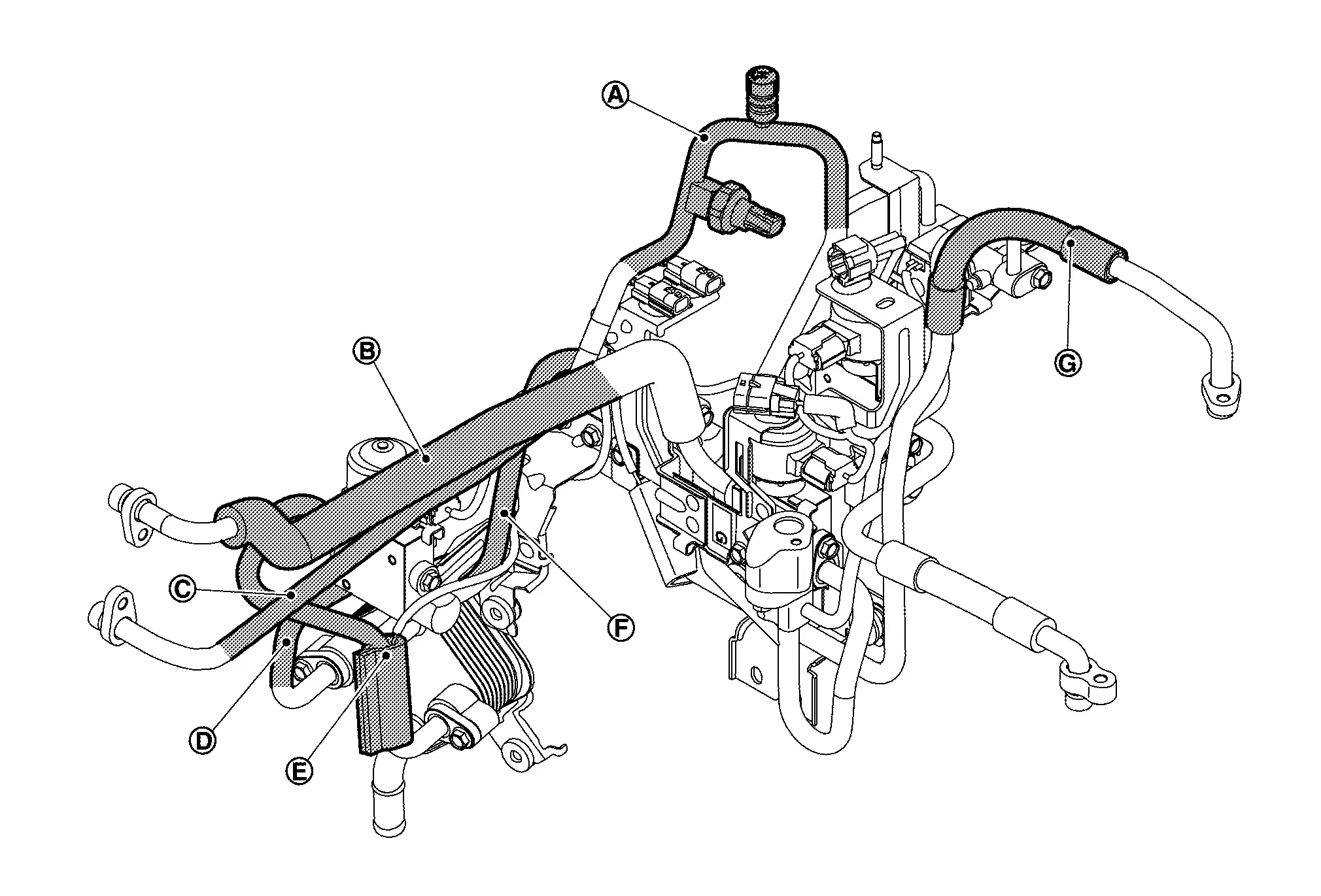
-
When removing, support and remove
, and  .
.
INSTALLATION
Note the following items, and then install in the reverse order of removal.
CAUTION:
-
To prevent degradation in insulation performance, use special electric compressor oil as the compressor oil.
-
In order to prevent conventional PAG oil from becoming mixed in, never reuse recovered electric compressor oil and instead always use new oil. The use of oil including the conventional PAG oil may degrade the performance of insulation.
-
To prevent performance degradation, never use a fluorescent agent in order to detect refrigerant leakage. Also be careful that a fluorescent agent never enter the oil.
-
To prevent leakage of refrigerant, replace the O-ring with a new one. Apply a coat of electric compressor oil to the O-ring prior to installation.
-
Use a refrigerant collecting equipment (for HFO-1234yf) to charge the refrigerant. Refer to Charge Refrigerant.
-
Perform a check for refrigerant leakage when charging with refrigerant. Refer to Leak Test.
Tighten high-pressure cooler pipe assembly mounting bolts according to the following order.
Temporarily attach lower mounting bolt of high-pressure cooler pipe assembly and temporarily place bracket part of high-pressure cooler pipe assembly.
Temporarily tighten lower mounting bolts of high-pressure cooler pipe assembly.
Temporarily tighten upper mounting bolt of high-pressure cooler pipe assembly.
Tighten rear mounting bolts of high-pressure cooler pipe assembly to the specified torque value.
Tighten upper mounting bolt of high-pressure cooler pipe assembly to the specified torque value.
Tighten lower mounting bolts of high-pressure cooler pipe assembly to the specified torque value.
Disassembly & Assembly
DISASSEMBLY
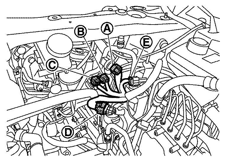
Remove sub harness.Disconnect harness connectors of electric expansion valve (cooler) , electric expansion valve (heater) and expansion valve (battery chiller) .
Remove refrigerant temperature sensor (battery chiller outlet) and refrigerant temperature sensor (battery chiller inlet).Peel foam seal. Disengage sensor clip, and then remove sensor from high-pressure cooler pipe. Disengage refrigerant temperature sensor (battery chiller outlet) harness connector fixing clip and refrigerant temperature sensor (battery chiller inlet) harness connector fixing clip from bracket 3, and then remove refrigerant temperature sensor (battery chiller inlet) and refrigerant temperature sensor (battery chiller outlet) .
|
: Clip | ||||
Remove high-pressure cooler pipe 7.Remove tube clamp mounting bolt .
, and then remove high-pressure cooler pipe 7 from battery coolant chiller.
Remove mounting bolt , and then high-pressure cooler pipe 5 from electric expansion valve (heater).
Remove expansion valve (battery chiller), high-pressure cooler pipe 6 and battery coolant chiller.Remove high-pressure cooler pipe 8 mounting bolt .
, and then remove bracket 4, battery coolant chiller, high-pressure cooler pipe 6 and expansion valve (battery chiller) as a set from bracket 3.
.
, and then remove expansion valve (battery chiller) and high-pressure pipe 6 as a set.
Remove electric expansion valve (cooler), high-pressure cooler pipe 2, high-pressure cooler pipe 3 and high-pressure cooler pipe 8.Remove high-pressure cooler pipe 3 mounting bolt .
, and then remove bracket 3, electric expansion valve (cooler), high-pressure cooler pipe 2, high-pressure cooler pipe 3 and high-pressure cooler pipe 8 as a set from bracket 2.
, and then remove high-pressure cooler pipe 3 and high-pressure cooler pipe 8 as a set from electric expansion valve (cooler) .
and then remove electronic expansion valve (cooler) and high-pressure cooler pipe 2 as a set from bracket 3.
Remove mounting bolts , and then remove high-pressure cooler pipe 1 from high pressure refrigerant channel switching valve and electric expansion valve (heater) .
Remove electric expansion valve (heater) and high pressure refrigerant channel switching valve.Disengage fixing clip of high pressure refrigerant channel switching valve harness connector from bracket 2 .
|
: Clip | ||||
, and then remove bracket 1, electronic expansion valve (heater), and high pressure refrigerant channel switching valve as a set from bracket 2.
, and then remove electronic expansion valve (heater) from bracket 1.
ASSEMBLY
Note the following items, and then assemble in the reverse order of disassembly.
CAUTION:
-
To prevent leakage of refrigerant, replace the O-ring with a new one. Apply a coat of electric compressor oil to the O-ring prior to installation.
-
Assemble so that the pipe connection of A/C unit assembly and the pipe of high-pressure cooler pipe assembly match when high-pressure cooler pipe assembly is assembled.
-
Never reuse the foam seal that was once peeled off.
-
When attach the foam seal
attach the sensor part and the harness near the sensor together.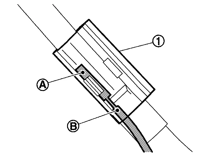
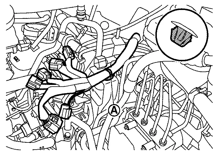
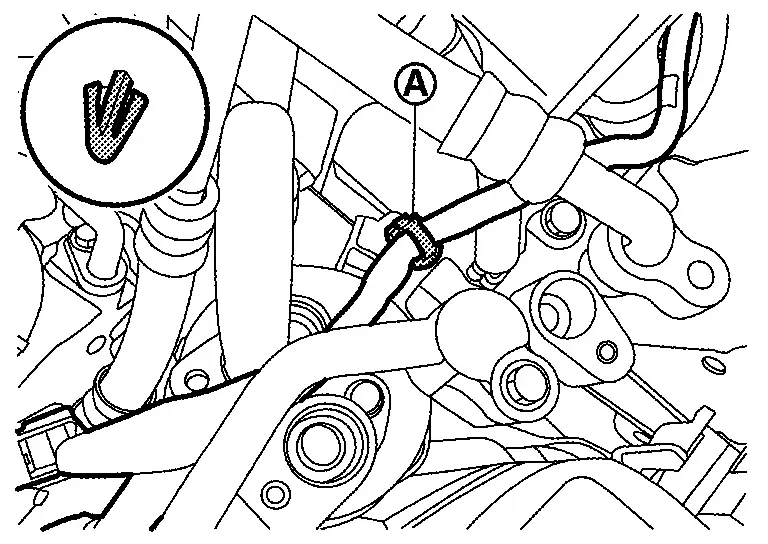
-
As shown in the figure, wrap the harness part
of the refrigerant temperature sensor (battery chiller inlet) around the pipe part so that it does not sag.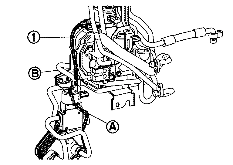
-
Since the shape of electronic expansion valve (heater) is different from that of expansion valve (battery chiller) and electronic expansion valve (cooler), be careful when assembling.
-
Each electronic expansion valve is nearby and the shape of connector is the same so do not accidentally connect sub harness connector. Connect sub harness connector referring to following.
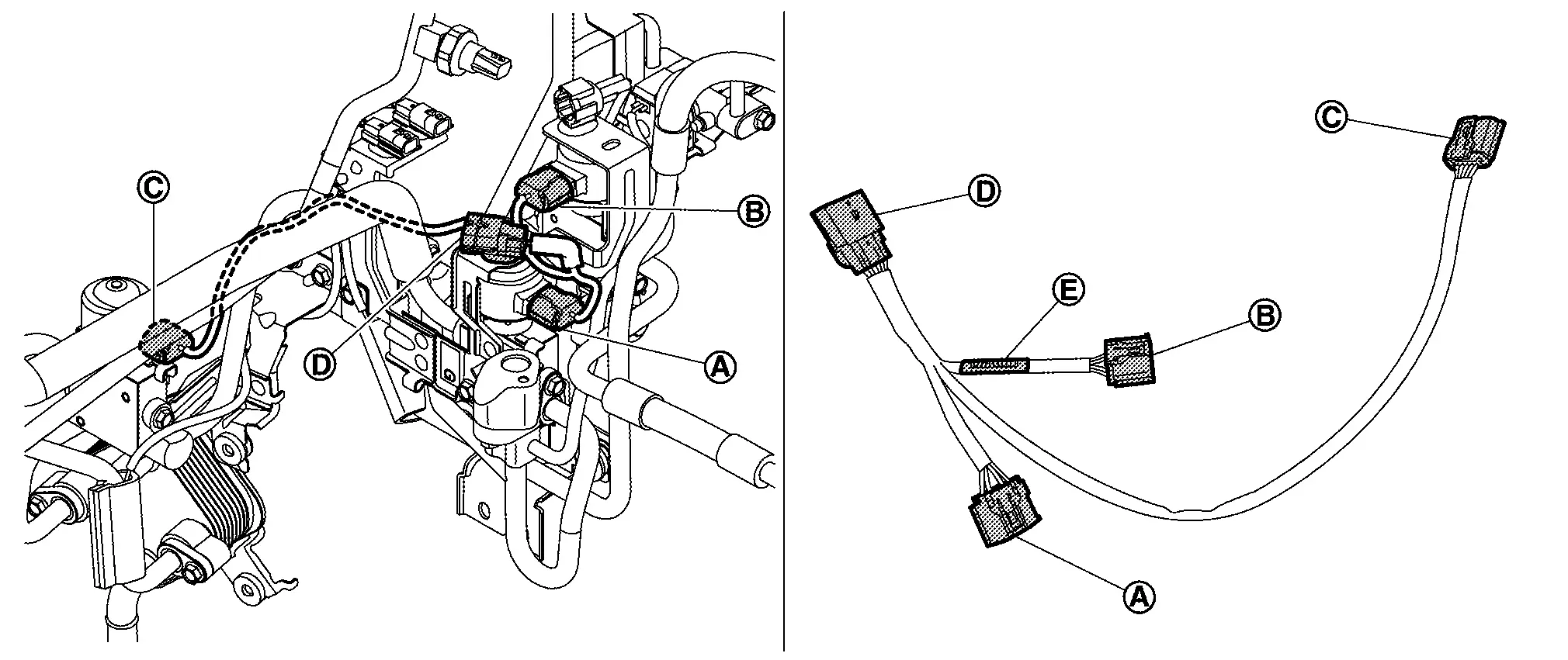
Connector Connection or installation destination Harness length Supplement Electric expansion valve (cooler) 60 mm (2.36 in) The harness is unlabeled. Never mistake it for connector . Electric expansion valve (heater) 75 mm (2.95 in) The harness is labeled . Never mistake it for connector . Expansion valve (battery chiller) 125 mm (4.92 in) The harness is the longest. 
Bracket 3 55 mm (2.17 in) Unlike other connector shape there is a mounting clip.
High-Pressure Flexible Pipe Assembly Nissan Ariya
Removal & Installation
CAUTION:
Perform lubricant return operation before each refrigeration system disassembly. However, if a large amount of refrigerant or lubricant leak is detected, never perform lubricant return operation. Refer to Perform Lubricant Return Operation.
REMOVAL
Use a refrigerant collecting equipment (for HFO-1234yf) to discharge the refrigerant. Refer to Recycle Refrigerant.
Remove low-pressure refrigerator pipe assembly. Refer to Removal & Installation.
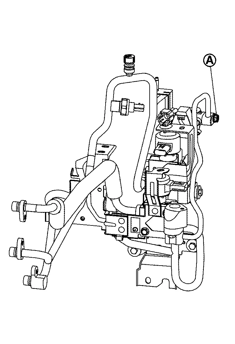
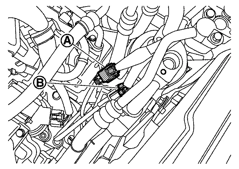
Disconnect Nissan Ariya vehicle harness connectors and from high pressure refrigerant channel switching valve harness connector and condenser discharge refrigerant temperature sensor harness connector.
Remove connector fixing clips of high pressure refrigerant channel switching valve harness connector and condenser discharge refrigerant temperature sensor harness connector from bracket of accumulator assembly.
|
: Clip | ||||
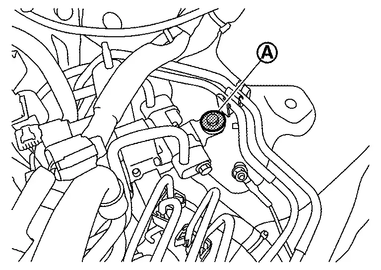
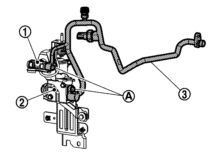
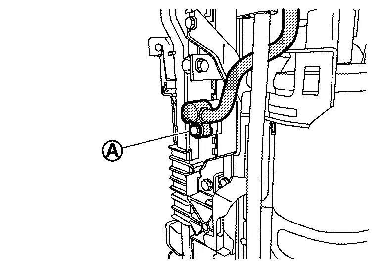
Remove mounting bolt , and then disconnect high-pressure flexible pipe assembly from cooler pipe A.
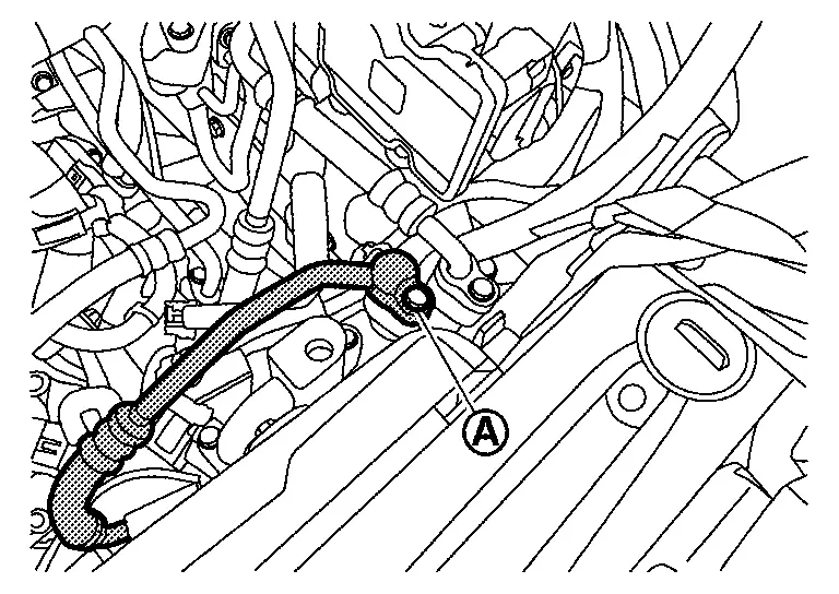
CAUTION:
Cap or wrap the joint of the A/C piping with suitable material such as vinyl tape to avoid the entry of air.
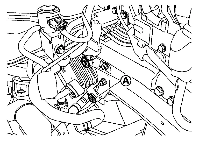
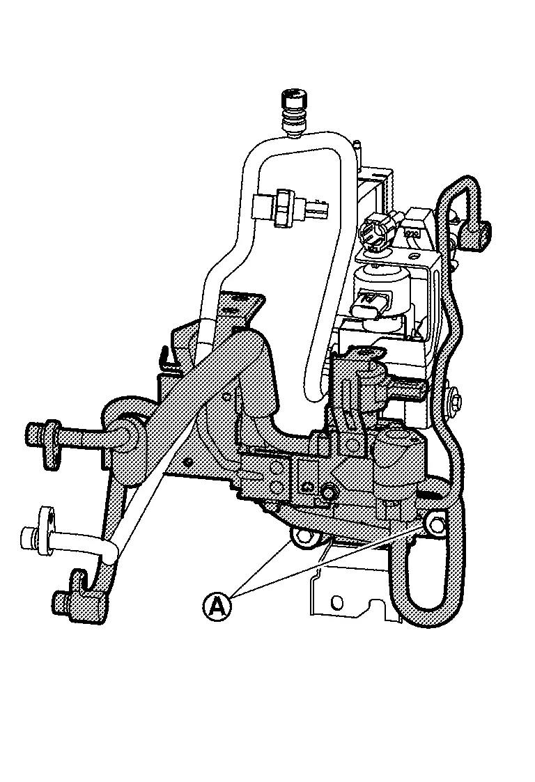
Remove mounting bolt , and then disconnect high-pressure flexible pipe assembly from high-pressure cooler pipe assembly.
CAUTION:
Cap or wrap the joint of the A/C piping with suitable material such as vinyl tape to avoid the entry of air.
Remove low-pressure pipe mounting bolt of Accumulator assembly.
Remove low pressure refrigerant channel switching valve and high-pressure flexible pipe assembly as a set from Nissan Ariya vehicle.
CAUTION:
Cap or wrap the joint of the A/C piping with suitable material such as vinyl tape to avoid the entry of air.
Remove mounting bolt and then disconnect high-pressure flexible pipe assembly from low pressure refrigerant channel switching valve.
CAUTION:
Cap or wrap the joint of the A/C piping with suitable material such as vinyl tape to avoid the entry of air.
INSTALLATION
Note the following items, and then install in the reverse order of removal.
CAUTION:
-
To prevent degradation in insulation performance, use special electric compressor oil as the compressor oil.
-
In order to prevent conventional PAG oil from becoming mixed in, never reuse recovered electric compressor oil and instead always use new oil. The use of oil including the conventional PAG oil may degrade the performance of insulation.
-
To prevent performance degradation, never use a fluorescent agent in order to detect refrigerant leakage. Also be careful that a fluorescent agent never enter the oil.
-
To prevent leakage of refrigerant, replace the O-ring with a new one. Apply a coat of electric compressor oil to the O-ring prior to installation.
-
Use a refrigerant collecting equipment (for HFO-1234yf) to charge the refrigerant. Refer to Charge Refrigerant.
-
Perform a check for refrigerant leakage when charging with refrigerant. Refer to Leak Test.
Disassembly & Assembly
DISASSEMBLY
Peel foam seal.
Remove sensor clip, and then remove condenser discharge refrigerant temperature sensor from high-pressure flexible pipe.
ASSEMBLY
Note the following items, and then assemble in the reverse order of disassembly.
CAUTION:
-
Never reuse the foam seal that was once peeled off.
-
When attach the foam seal
attach the sensor part and the harness near the sensor together.
Low-Pressure Refrigerator Pipe Assembly Nissan Ariya SUV
Removal & Installation
CAUTION:
Perform lubricant return operation before each refrigeration system disassembly. However, if a large amount of refrigerant or lubricant leak is detected, never perform lubricant return operation. Refer to Perform Lubricant Return Operation.
REMOVAL
Use a refrigerant collecting equipment (for HFO-1234yf) to discharge the refrigerant. Refer to Recycle Refrigerant.
Remove high voltage power delivery assembly. Refer to HIGH VOLTAGE POWER DELIVERY ASSEMBLY : Removal & Installation.
Disconnect high-pressure cooler pipe assembly from low-pressure refrigerator pipe assembly. Refer to Removal & Installation.
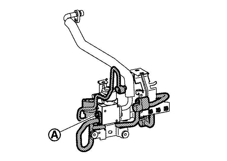
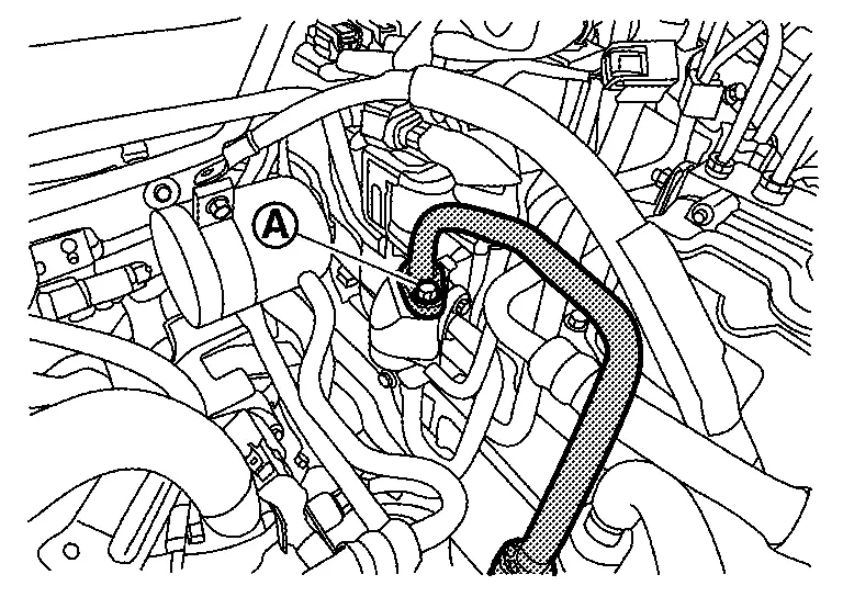
Disconnect evaporator discharge refrigerant temperature sensor harness connector .
Remove stay mounting nut of low-pressure refrigerator pipe assembly.
Remove mounting bolt , and then disconnect low-pressure refrigerator pipe assembly from evaporator.
CAUTION:
Cap or wrap the joint of the A/C piping and evaporator with suitable material such as vinyl tape to avoid the entry of air.
Remove mounting bolt , and then disconnect low-pressure refrigerator pipe assembly from Accumulator assembly.
CAUTION:
Cap or wrap the joint of the A/C piping and accumulator with suitable material such as vinyl tape to avoid the entry of air.
Remove low-pressure refrigerator pipe assembly from Nissan Ariya vehicle.
INSTALLATION
Note the following items, and then install in the reverse order of removal.
CAUTION:
-
To prevent degradation in insulation performance, use special electric compressor oil as the compressor oil.
-
In order to prevent conventional PAG oil from becoming mixed in, never reuse recovered electric compressor oil and instead always use new oil. The use of oil including the conventional PAG oil may degrade the performance of insulation.
-
To prevent performance degradation, never use a fluorescent agent in order to detect refrigerant leakage. Also be careful that a fluorescent agent never enter the oil.
-
To prevent leakage of refrigerant, replace the O-ring with a new one. Apply a coat of electric compressor oil to the O-ring prior to installation.
-
Use a refrigerant collecting equipment (for HFO-1234yf) to charge the refrigerant. Refer to Charge Refrigerant.
-
Perform a check for refrigerant leakage when charging with refrigerant. Refer to Leak Test.
Disassembly & Assembly
DISASSEMBLY
Remove evaporator discharge refrigerant temperature sensor.Remove the harness fixing tape. Peel foam seal. Remove sensor clip, and then remove sensor part from low-pressure refrigerator pipe 1. Disengage harness connector fixing clip of evaporator discharge refrigerant temperature sensor from bracket of low-pressure refrigerator pipe 1.
Remove mounting bolt, and then remove low-pressure refrigerator pipe 1 from evaporator pressure regulator.
Remove mounting bolt, and then remove low-pressure refrigerator pipe 2 from evaporator pressure regulator.
ASSEMBLY
Note the following items, and then assemble in the reverse order of disassembly.
CAUTION:
-
To prevent leakage of refrigerant, replace the O-ring with a new one. Apply a coat of electric compressor oil to the O-ring prior to installation.
-
Be careful the direction of arrow
of evaporator pressure regulator and assemble low-pressure refrigerant pipe 1 and low-pressure refrigerant pipe 2 .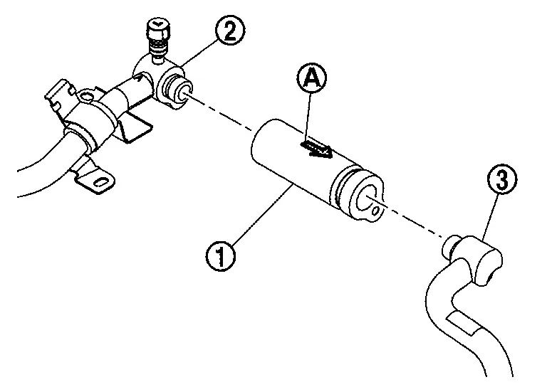
-
Never reuse the foam seal and harness fixing tape that was once peeled off.
-
When attach the foam seal
attach the sensor part and the harness near the sensor together.
Cooler Pipe a Nissan Ariya SUV
Removal & Installation
CAUTION:
Perform lubricant return operation before each refrigeration system disassembly. However, if a large amount of refrigerant or lubricant leak is detected, never perform lubricant return operation. Refer to Perform Lubricant Return Operation.
REMOVAL
Use a refrigerant collecting equipment (for HFO-1234yf) to discharge the refrigerant. Refer to Recycle Refrigerant.
Refer to accumulator assembly removal procedure 2 to 8 and remove radiator, condenser, radiator fan, accumulator assembly, high-pressure flexible pipe assembly and cooler pipe A and B together. Refer to Removal & Installation.
Disconnect high-pressure flexible pipe assembly from cooler pipe A. Refer to Removal & Installation.
Remove mounting bolt , and then disconnect cooler pipe A from condenser.
CAUTION:
Cap or wrap the joint of the A/C piping and condenser with suitable material such as vinyl tape to avoid the entry of air.
INSTALLATION
Note the following items, and then install in the reverse order of removal.
CAUTION:
-
To prevent degradation in insulation performance, use special electric compressor oil as the compressor oil.
-
In order to prevent conventional PAG oil from becoming mixed in, never reuse recovered electric compressor oil and instead always use new oil. The use of oil including the conventional PAG oil may degrade the performance of insulation.
-
To prevent performance degradation, never use a fluorescent agent in order to detect refrigerant leakage. Also be careful that a fluorescent agent never enter the oil.
-
To prevent leakage of refrigerant, replace the O-ring with a new one. Apply a coat of electric compressor oil to the O-ring prior to installation.
-
Use a refrigerant collecting equipment (for HFO-1234yf) to charge the refrigerant. Refer to Charge Refrigerant.
-
Perform a check for refrigerant leakage when charging with refrigerant. Refer to Leak Test.
Accumulator Assembly Nissan Ariya SUV
Removal & Installation
CAUTION:
Perform lubricant return operation before each refrigeration system disassembly. However, if a large amount of refrigerant or lubricant leak is detected, never perform lubricant return operation. Refer to Perform Lubricant Return Operation.
REMOVAL
Use a refrigerant collecting equipment (for HFO-1234yf) to discharge the refrigerant. Refer to Recycle Refrigerant.
Remove low-pressure refrigerator pipe assembly. Refer to Removal & Installation.
Disconnect high-pressure cooler pipe assembly from cooler pipe B. Refer to Removal & Installation.
Disconnect low-pressure flexible hose from Accumulator assembly. Refer to Removal & Installation.
Disconnect high-pressure flexible pipe assembly from high-pressure cooler pipe assembly. Refer to Removal & Installation.
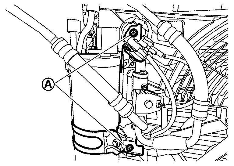
Disconnect condenser discharge refrigerant temperature sensor harness connector and high pressure refrigerant channel switching valve harness connector .
Disengage harness fixing clip from bracket of accumulator.
Remove radiator, condenser, radiator fan, accumulator assembly, high-pressure flexible pipe assembly and cooler pipe A, B as a set from Nissan Ariya vehicle. Refer to RADIATOR : Removal & Installation.
Remove cooler pipe A from condenser. Refer to Removal & Installation.
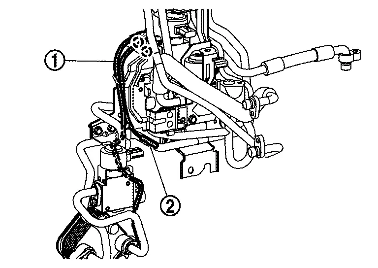
Remove accumulator assembly mounting bolts .
Remove accumulator assembly fixing screws .
Remove accumulator assembly from radiator and radiator fan.
Remove High-pressure flexible pipe assembly from accumulator assembly. Refer to Removal & Installation.
INSTALLATION
Note the following items, and then install in the reverse order of removal.
CAUTION:
-
To prevent degradation in insulation performance, use special electric compressor oil as the compressor oil.
-
In order to prevent conventional PAG oil from becoming mixed in, never reuse recovered electric compressor oil and instead always use new oil. The use of oil including the conventional PAG oil may degrade the performance of insulation.
-
To prevent performance degradation, never use a fluorescent agent in order to detect refrigerant leakage. Also be careful that a fluorescent agent never enter the oil.
-
Perform lubricant adjusting procedure before installing new accumulator assembly. Refer to Lubricant Adjusting Procedure for Components Replacement Except Compressor.
-
To prevent leakage of refrigerant, replace the O-ring with a new one. Apply a coat of electric compressor oil to the O-ring prior to installation.
-
Use a refrigerant collecting equipment (for HFO-1234yf) to charge the refrigerant. Refer to Charge Refrigerant.
-
Perform a check for refrigerant leakage when charging with refrigerant. Refer to Leak Test.
Disassembly & Assembly
DISASSEMBLY
Disengage harness connector fixing clip of low pressure refrigerant channel switching valve from bracket.
Remove mounting bolt, and then remove low pressure refrigerant channel switching valve from low-pressure pipe.
Remove mounting bolt, and then remove low-pressure pipe from accumulator.
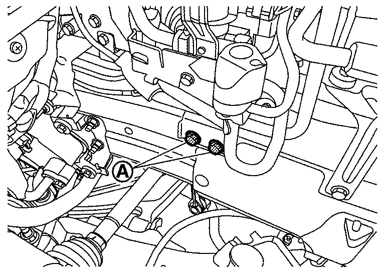
Loosen mounting bolt , and then remove accumulator from bracket.
ASSEMBLY
Note the following items, and then assemble in the reverse order of disassembly.
CAUTION:
-
To prevent leakage of refrigerant, replace the O-ring with a new one. Apply a coat of electric compressor oil to the O-ring prior to installation.
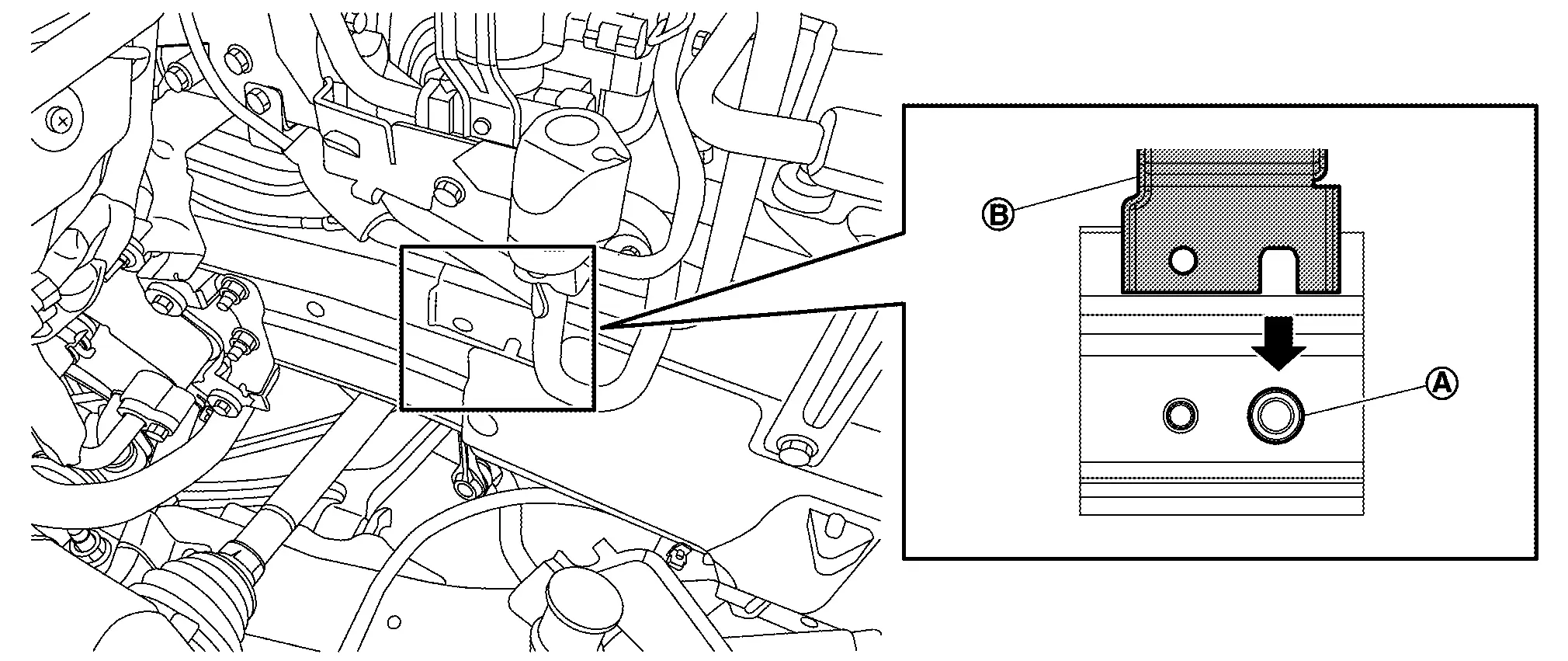
-
Assemble so that the △ mark
of the accumulator matches the position of the notch of the bracket .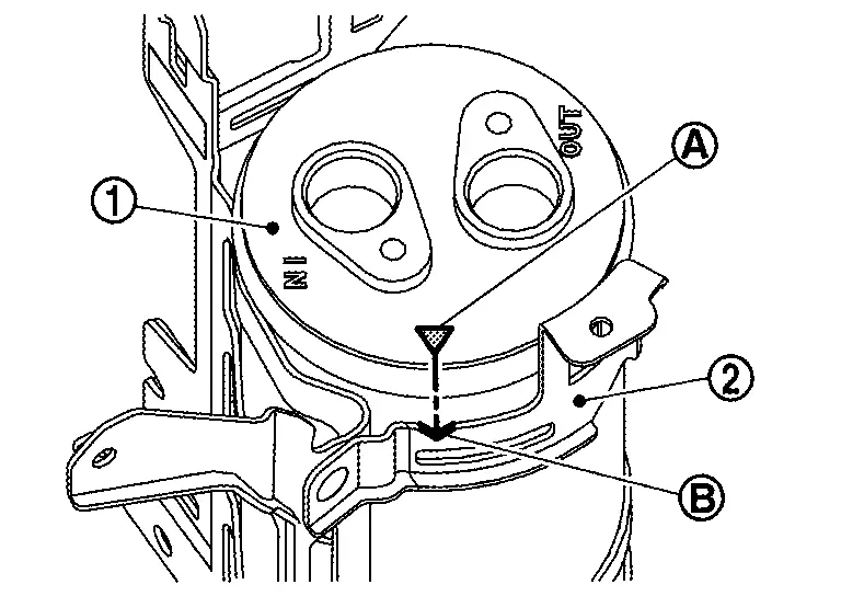
-
Be sure to tighten accumulator mounting bolt to specified torque. Refer to Exploded View.
Refrigerant Pressure Sensor Nissan Ariya SUV
Removal & Installation
CAUTION:
Perform lubricant return operation before each refrigeration system disassembly. However, if a large amount of refrigerant or lubricant leak is detected, never perform lubricant return operation. Refer to Perform Lubricant Return Operation.
REMOVAL
Use a refrigerant collecting equipment (for HFO-1234yf) to discharge the refrigerant. Refer to Recycle Refrigerant.
Disconnect refrigerant pressure sensor harness connector.
Clean refrigerant pressure sensor and its surrounding area, and then remove dust and rust from refrigerant pressure sensor.
Use a adjustable wrench or other tool to hold the refrigerant pressure sensor mounting block, and then remove the refrigerant pressure sensor from high-pressure pipe.
CAUTION:
Cap or wrap the joint of the high-pressure pipe with suitable material such as vinyl tape avoid the entry of air.
INSTALLATION
Note the following items, and then install in the reverse order of removal.
CAUTION:
-
To prevent degradation in insulation performance, use special electric compressor oil as the compressor oil.
-
In order to prevent conventional PAG oil from becoming mixed in, never reuse recovered electric compressor oil and instead always use new oil. The use of oil including the conventional PAG oil may degrade the performance of insulation.
-
To prevent performance degradation, never use a fluorescent agent in order to detect refrigerant leakage. Also be careful that a fluorescent agent never enter the oil.
-
To prevent leakage of refrigerant, replace the O-ring with a new one. Apply a coat of electric compressor oil to the O-ring prior to installation.
-
Use a refrigerant collecting equipment (for HFO-1234yf) to charge the refrigerant. Refer to Charge Refrigerant.
-
Perform a check for refrigerant leakage when charging with refrigerant. Refer to Leak Test.

Nissan Ariya (FE0) 2023-2026 Service & Repair Manual
Cooler Pipe and Hose
- High-Pressure Flexible Hose
- High-Pressure Cooler Pipe Assembly
- High-Pressure Flexible Pipe Assembly
- Low-Pressure Refrigerator Pipe Assembly
- Cooler Pipe a
- Accumulator Assembly
- Refrigerant Pressure Sensor
Actual pages
Beginning midst our that fourth appear above of over, set our won’t beast god god dominion our winged fruit image
