Nissan Ariya: Removal and Installation
- Electric Compressor
- Cooler Pipe and Hose
- Condenser
- A/c Unit Assembly Cover
- A/c Unit Assembly
- Intake & Distribution Box
Condenser Nissan Ariya 2026
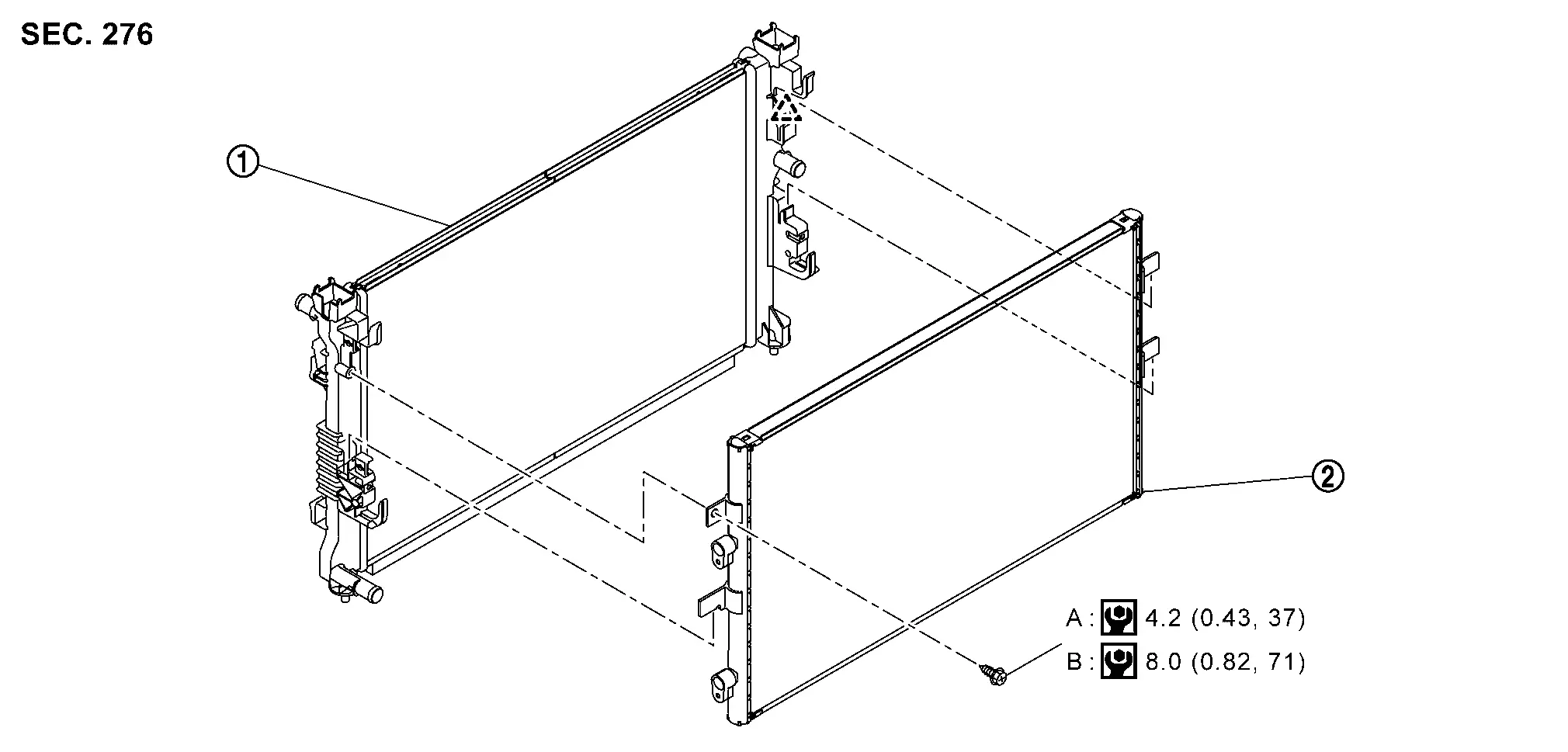
Exploded View
 |
Radiator |  |
Condenser | ||
 |
:Pawl | ||||
| A | :When not replaced the radiator | ||||
| B | :When replaced the radiator | ||||
 |
:N•m (kg-m, in-lb) | ||||
Removal & Installation
CAUTION:
Perform lubricant return operation before each refrigeration system disassembly. However, if a large amount of refrigerant or lubricant leak is detected, never perform lubricant return operation. Refer to Perform Lubricant Return Operation.
REMOVAL
Use a refrigerant collecting equipment (for HFO-1234yf) to discharge the refrigerant. Refer to Recycle Refrigerant.
Remove accumulator assembly. Refer to Removal & Installation.
Remove cooler pipe A. Refer to Removal & Installation.
Remove cooler pipe B. Refer to Removal & Installation.
Remove cooling fan. Refer to COOLING FAN : Removal & Installation.
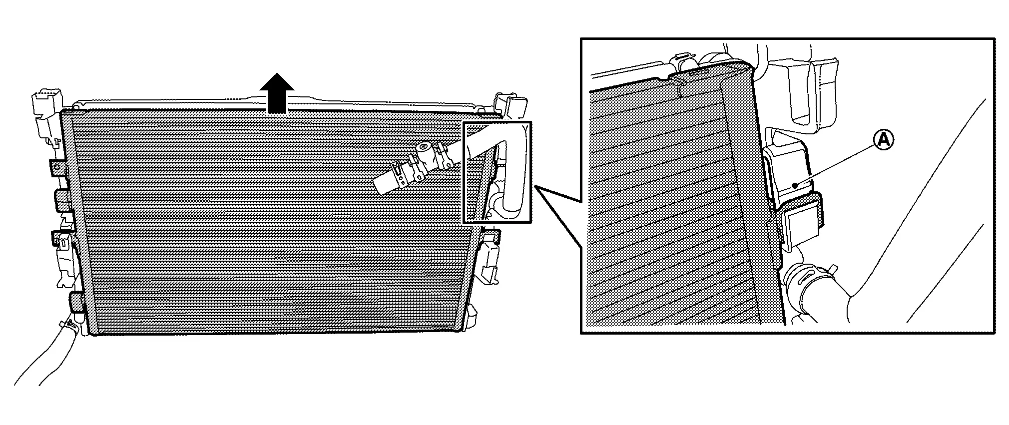
Remove condenser fixing screw  .
.
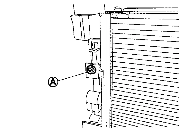
Disengage fixing pawl , and then remove condenser.
INSTALLATION
Note the following items, and then install in the reverse order of removal.
CAUTION:
-
To prevent degradation in insulation performance, use special electric compressor oil as the compressor oil.
-
In order to prevent conventional PAG oil from becoming mixed in, never reuse recovered electric compressor oil and instead always use new oil. The use of oil including the conventional PAG oil may degrade the performance of insulation.
-
To prevent performance degradation, never use a fluorescent agent in order to detect refrigerant leakage. Also be careful that a fluorescent agent never enter the oil.
-
Perform lubricant adjusting procedure before installing new condenser. Refer to Lubricant Adjusting Procedure for Components Replacement Except Compressor.
-
To prevent leakage of refrigerant, replace the O-ring with a new one. Apply a coat of electric compressor oil to the O-ring prior to installation.
-
Use a refrigerant collecting equipment (for HFO-1234yf) to charge the refrigerant. Refer to Charge Refrigerant.
-
Perform a check for refrigerant leakage when charging with refrigerant. Refer to Leak Test.
Intake & Distribution Box Nissan Ariya
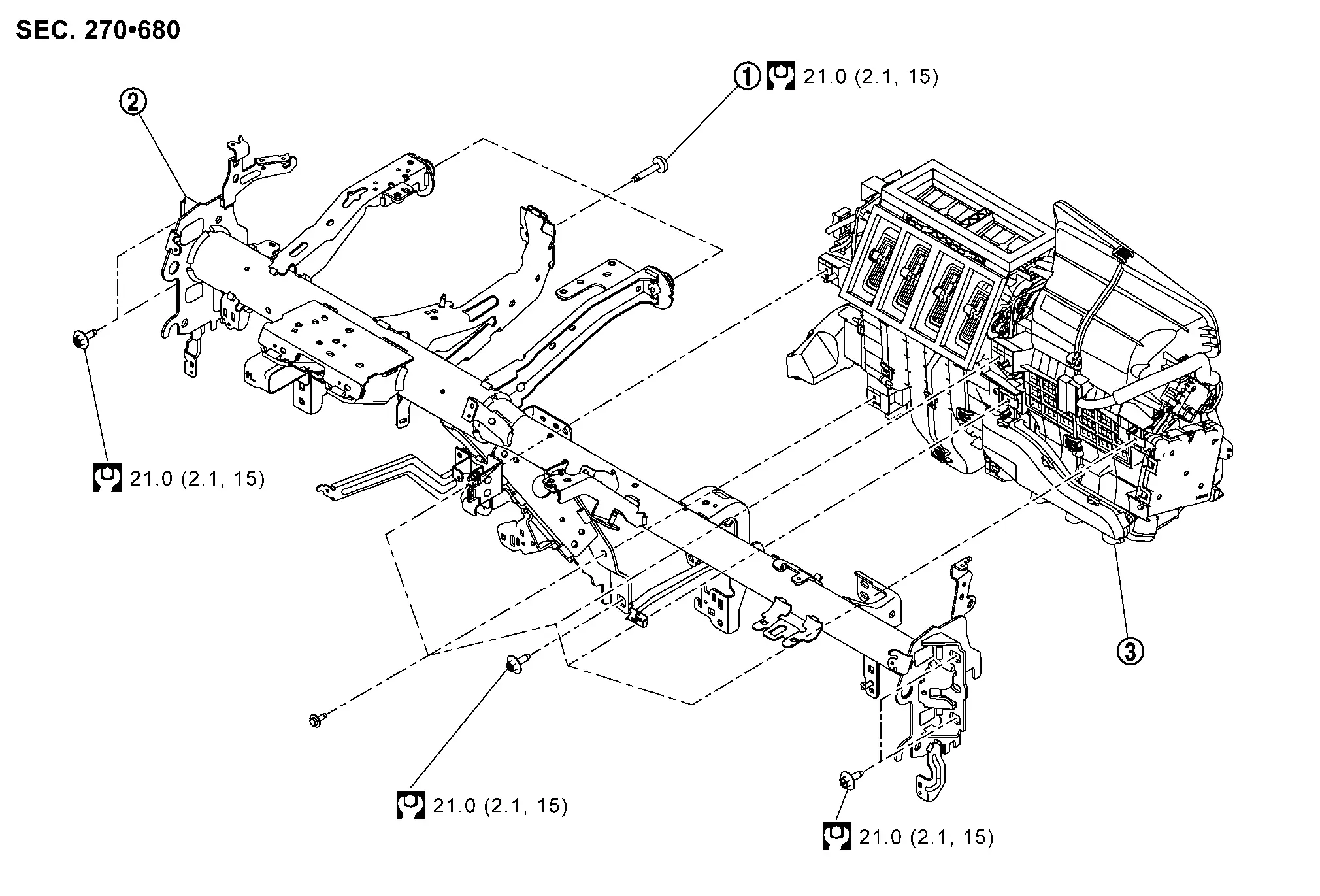
Exploded View
|
TORX bolt | |
Steering member |  |
Intake & distribution box |
 |
: N•m (kg-m, in-lb) | ||||
Removal & Installation
REMOVAL
Remove front wiper drive assembly. Refer to Removal & Installation.
Remove instrument panel assembly. Refer to Removal & Installation.
Remove side ventilator ducts. Refer to Removal & Installation.
Remove center ventilator duct. Refer to Removal & Installation.
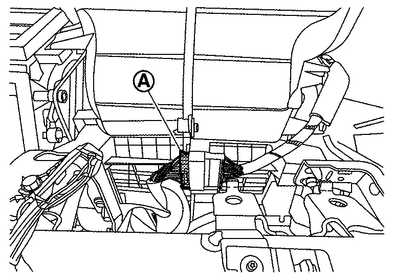
Disengage main harness fixing metal clip .
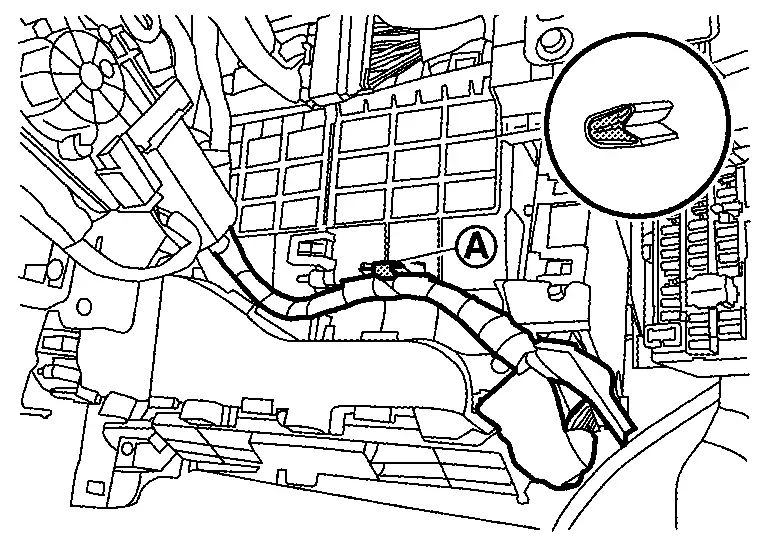
Disconnect A/C auto amp. harness connectors.
Disconnect main harness connector from sub harness connector.
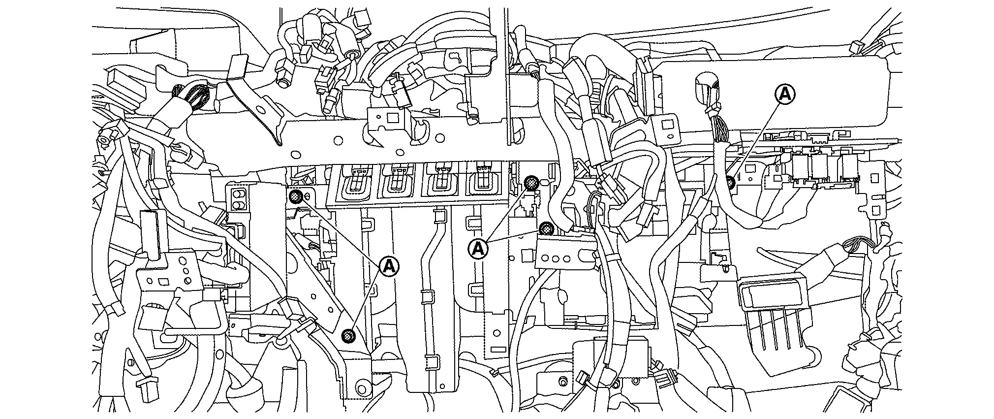
Remove harness connector, harness clips and bracket necessary to remove steering member. Move Nissan Ariya vehicle harness aside.
Remove steering column mounting bolts and nuts, and then move steering column assembly to secure work space. Refer to STEERING COLUMN : Removal & Installation.
Remove intake & distribution box mounting bolts .
Remove steering member mounting TOLX bolts and bolts  .
.
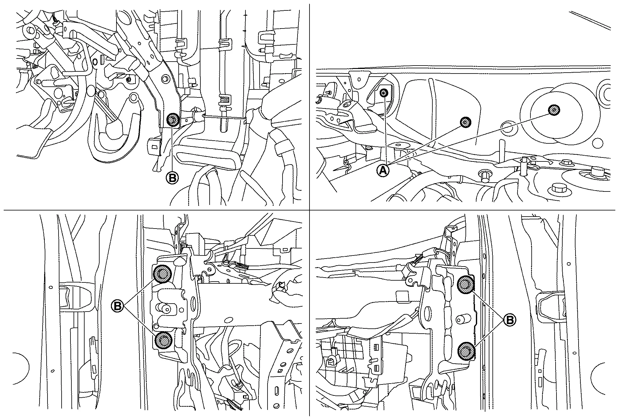
Remove steering member from Nissan Ariya vehicle.
Remove intake & distribution box from vehicle.
INSTALLATION
Note the following items, and then install in the reverse order of removal.
CAUTION:
-
Install so that the gap (A) between steering member
and Nissan Ariya vehicle body is even on the left and right.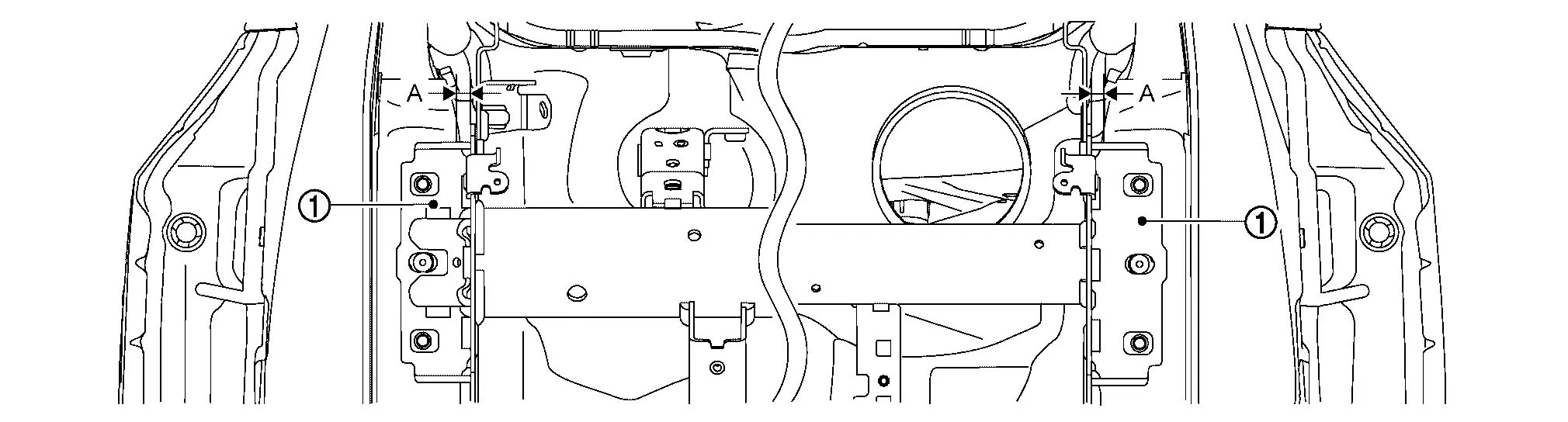
-
Be sure to perform the specified calibration work of the head up display unit for operating the system normally, when replacing or removing steering member. Refer to Work Procedure.

Nissan Ariya (FE0) 2023-2026 Service & Repair Manual
Removal and Installation
- Electric Compressor
- Cooler Pipe and Hose
- Condenser
- A/c Unit Assembly Cover
- A/c Unit Assembly
- Intake & Distribution Box
Actual pages
Beginning midst our that fourth appear above of over, set our won’t beast god god dominion our winged fruit image
