Nissan Ariya: Dtc/circuit Diagnosis
- B2001-45 Intelligent Key Unit
- B2010-1c Battery Voltage
- B203e-14 Outside Antenna
- B2046-42 Eeprom
- B2086-23 Request Sw (bd/tr)
- B2087-08 One Touch Sensor (fl)
- B2087-11 One Touch Sensor (fl)
- B2087-23 One Touch Sensor (fl)
- B2409-12 Half Latch Switch
- B2409-14 Half Latch Switch
- B2416-15 Touch Sensor Circuit Rh Open
- B2422-78 Back Door Position Abnormal
- B2426-11 Spindle Sensor Lh
- B2426-12 Spindle Sensor Lh
- B2426-13 Spindle Sensor Lh
- B2426-25 Spindle Sensor Lh
- B2428-44 Automatic Back Door Control Unit
- B2428-54 Automatic Back Door Control Unit
- B242a-11 Closure Motor
- B242a-98 Closure Motor
- B242f-11 Automatic Back Door Warning Buzzer
- B242f-13 Automatic Back Door Warning Buzzer
- B2f06-11 Trunk/back Door Opener Sw
- U0075-00 Communication Bus C Off
- U2118-87 Can Comm Circuit
- U2141-87 Can Comm Circuit
- U2148-87 Can Comm Circuit. Intelligent Key Unit
- U214e-87 Can Comm Circuit. Intelligent Key Unit
- U214f-87 Can Comm Circuit. Intelligent Key Unit
- U215b-87 Can Comm Circuit. Intelligent Key Unit
- Automatic Back Door Close Switch
- Automatic Back Door Warning Buzzer
- Back Door Switch. With Automatic Back Door System
- Back Door Opener Actuator
- Back Door Request Switch
- Door Lock Actuator. Driver Side
- Door Lock and Unlock Switch. Driver Side
- Door Switch
- Hazard Function
- Intelligent Key Battery
- Intelligent Key Warning Buzzer
- Power Supply and Ground Circuit
- Touch Sensor
- Unlock Sensor
- Serial Signal Circuit
B2001-45 Intelligent Key Unit Nissan Ariya SUV
DTC Description
DTC DETECTION LOGIC
| DTC No. | CONSULT screen items | DTC Detection Condition | |
|---|---|---|---|
| B2001–45 | Intelligent Key unit | Diagnosis condition | Power switch ON |
| Signal (terminal) | — | ||
| Threshold | Intelligent Key unit is internal malfunctioning | ||
| Diagnosis delay time | 1 second or less | ||
POSSIBLE CAUSE
Intelligent Key unit
FAIL-SAFE
—
DTC CONFIRMATION PROCEDURE
DTC CONFIRMATION
 With CONSULT
-
Power switch ON.
-
Select “Self Diagnostic Result” mode of “INTELLIGENT KEY” using CONSULT.
Is DTC detected?
YES>>Refer to DTC Diagnosis Procedure.
NO–1>>To check malfunction symptom before repair: Refer to Intermittent Incident.
NO–2>>Confirmation after repair: INSPECTION END
DTC Diagnosis Procedure
REPLACE INTELLIGENT KEY UNIT
When DTC “B2001–45” is detected, replace Intelligent Key unit.
>>
Replace Intelligent Key unit. Refer to Removal and Installation.
B2010-1c Battery Voltage Nissan Ariya 1st generation
DTC Description
DTC DETECTION LOGIC
| DTC No. | CONSULT screen items | DTC Detection Condition | |
|---|---|---|---|
| B2010–1C | Battery voltage | Diagnosis condition | All times |
| Signal (terminal) | Intelligent Key unit battery power supply signal | ||
| Threshold | Less than 4 V or more than 16 V | ||
| Diagnosis delay time | — | ||
POSSIBLE CAUSE
-
Harness or connector (power supply circuit)
-
Intelligent Key unit
-
Battery
FAIL-SAFE
—
DTC CONFIRMATION PROCEDURE
DTC CONFIRMATION
With CONSULT
-
Power switch ON.
-
Select the “Self Diagnostic Result” of “INTELLIGENT KEY” using CONSULT.
Is DTC detected?
YES>>Refer to DTC Diagnosis Procedure.
NO–1>>To check malfunction symptom before repair: Refer to Intermittent Incident.
NO–2>>Confirmation after repair: INSPECTION END
DTC Diagnosis Procedure
CHECK BATTERY VOLTAGE
Measure the battery voltage. Refer to Work Flow.
Is the inspection result normal?
YES>>GO TO 2.
NO>>Replace battery.
CHECK POWER SUPPLY CIRCUIT
Check Intelligent Key unit power supply circuit. Refer to Diagnosis Procedure.
Is the inspection result normal?
YES>>Replace Intelligent Key unit. Refer to Removal and Installation.
NO>>Repair the malfunctioning part.
B203e-14 Outside Antenna Nissan Ariya
DTC Description
DTC DETECTION LOGIC
| DTC No. | CONSULT screen items | DTC detecting condition | |
|---|---|---|---|
| B203E–14 | Outside antenna | Diagnosis condition | Work support “Inside/outside antenna diagnosis”: activated |
| Signal (terminal) | Outside key antenna (rear door LH) signal (Intelligent Key unit connector terminal: 35, 36) | ||
| Threshold | Outside key antenna (rear door LH) circuit is open or shorted | ||
| Diagnosis delay time | 1 second or less | ||
POSSIBLE CAUSE
-
Intelligent Key unit
-
Outside key antenna (rear door LH)
-
Harness or connector [outside key antenna (rear door LH) circuit is open or shorted]
FAIL-SAFE
—
DTC CONFIRMATION PROCEDURE
PERFORM DTC CONFIRMATION PROCEDURE
With CONSULT
-
Select “Inside/outside antenna diagnosis” in “Work support” mode of “INTELLIGENT KEY”.
-
Select the “Self Diagnosis Result” mode of “INTELLIGENT KEY” using CONSULT.
Is DTC detected?
YES>>Refer to DTC Diagnosis Procedure.
NO-1>>To check malfunction symptom before repair: Refer to Intermittent Incident.
NO-2>>Confirmation after repair: INSPECTION END
DTC Diagnosis Procedure
CHECK OUTSIDE KEY ANTENNA INPUT SIGNAL 1
-
Power switch ON.
-
Check signal between Intelligent Key unit harness connector and ground using oscilloscope.
(+) (–) Condition Signal
(Reference value)Intelligent Key unit Connector Terminal M79 35 Ground Power switch pressed when Intelligent Key is in the antenna detection area 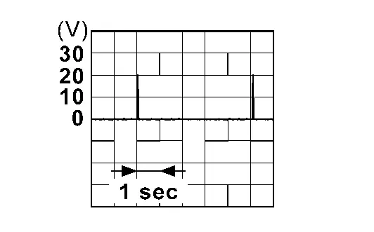
Power switch pressed when Intelligent Key is not in the antenna detection area 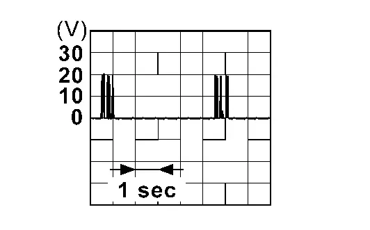
36 Power switch pressed when Intelligent Key is in the antenna detection area Power switch pressed when Intelligent Key is not in the antenna detection area
Is the inspection result normal?
YES>>Replace Intelligent Key unit. Refer to Removal and Installation.
NO>>GO TO 2.
CHECK OUTSIDE KEY ANTENNA CIRCUIT
-
Power switch OFF.
-
Disconnect Intelligent Key unit connector and outside key antenna (rear door LH) connector.
-
Check continuity between Intelligent Key unit harness connector and outside key antenna (rear door LH) connector.
Intelligent Key unit Outside key antenna (rear door LH) Continuity Connector Terminal Connector Terminal M79 35 D103 2 Existed 36 1 -
Check continuity between Intelligent Key unit harness connector and ground.
Intelligent Key unit — Continuity Connector Terminal M79 35 Ground Not existed 36
Is the inspection result normal?
YES>>GO TO 3.
NO>>Repair or replace harness.
CHECK OUTSIDE KEY ANTENNA INPUT SIGNAL 2
-
Replace outside key antenna (rear door LH). (New antenna or other antenna)
-
Connect Intelligent Key unit connector and outside key antenna (rear door LH) connector.
-
Power switch ON.
-
Check signal between Intelligent Key unit harness connector and ground using oscilloscope.
(+) (–) Condition Signal
(Reference value)Intelligent Key unit Connector Terminal M79 35 Ground Power switch pressed when Intelligent Key is in the antenna detection area Power switch pressed when Intelligent Key is not in the antenna detection area 36 Power switch pressed when Intelligent Key is in the antenna detection area Power switch pressed when Intelligent Key is not in the antenna detection area
Is the inspection result normal?
YES>>Replace outside key antenna (rear door LH). Refer to Removal and Installation.
NO>>Replace Intelligent Key unit. Refer to Removal and Installation.
B2046-42 Eeprom Nissan Ariya 2023
DTC Description
DTC DETECTION LOGIC
| DTC No. | CONSULT screen items | DTC Detection Condition | |
|---|---|---|---|
| B2046–42 | EEPROM | Diagnosis condition | Power switch ON |
| Signal (terminal) | — | ||
| Threshold | EEPROM in Intelligent Key unit is malfunctioning | ||
| Diagnosis delay time | 1 second or less | ||
POSSIBLE CAUSE
-
Intelligent Key unit
-
Mistook the "Configuration"
FAIL-SAFE
—
DTC CONFIRMATION PROCEDURE
DTC CONFIRMATION
With CONSULT
-
Power switch ON.
-
Select “Self Diagnostic Result” mode of “INTELLIGENT KEY” using CONSULT.
Is DTC detected?
YES>>Refer to DTC Diagnosis Procedure.
NO–1>>To check malfunction symptom before repair: Refer to Intermittent Incident.
NO–2>>Confirmation after repair: INSPECTION END
DTC Diagnosis Procedure
PERFORM "CONFIGURATION"
With CONSULT
-
Perform "Configuration".
-
Erase DTC.
-
Power switch OFF.
-
Power switch ON.
-
Select “Self Diagnostic Result” mode of “INTELLIGENT KEY” using CONSULT.
Is DTC detected?
YES>>GO TO 2.
NO>>INSPECTION END
REPLACE INTELLIGENT KEY UNIT
Replace Intelligent Key unit. Refer to Intermittent Incident.
>>
INSPECTION END
B2086-23 Request Sw (bd/tr) Nissan Ariya SUV
DTC Description
DTC DETECTION LOGIC
| DTC No. | CONSULT screen terms | DTC Detection Condition | |
|---|---|---|---|
| B2086–23 | Request switch (Back door/Trunk) | Diagnosis condition | Power switch ON |
| Signal (terminal) | Back door request switch signal (Intelligent Key unit connector terminal 5) | ||
| Threshold | Intelligent Key unit detects that the back door request switch is stuck ON | ||
| Diagnosis delay time | 10 seconds or more | ||
POSSIBLE CAUSE
-
Back door opener switch assembly (back door request switch)
-
Harness or connector
[Back door opener switch assembly (back door request switch) circuit is shorted]
-
Intelligent Key unit
FAIL-SAFE
—
DTC CONFIRMATION PROCEDURE
CHECK SELF-DIAG RESULT
With CONSULT
-
Power switch ON and wait for 10 seconds or more.
-
Select “Self Diagnostic Result” mode of “INTELLIGENT KEY” using CONSULT.
Is DTC detected?
YES>>Refer to DTC Diagnosis Procedure.
NO-1>>To check malfunction symptom before repair: Refer to Intermittent Incident.
NO-2>>Confirmation after repair: INSPECTION END
DTC Diagnosis Procedure
CHECK BACK DOOR REQUEST SWITCH INPUT SIGNAL
-
Power switch OFF.
-
Disconnect back door opener switch assembly connector.
-
Check voltage between back door opener switch assembly harness connector and ground.
(+) (–) Voltage Back door opener switch assembly Connector Terminal D121 4 Ground 12 V
Is the inspection result normal?
YES>>GO TO 3.
NO>>GO TO 2.
CHECK BACK DOOR REQUEST SWITCH CIRCUIT
-
Disconnect Intelligent Key unit connector.
-
Check continuity between back door opener switch assembly harness connector and Intelligent Key unit harness connector.
Back door opener switch assembly Intelligent Key unit Continuity Connector Terminal Connector Terminal D121 4 M79 5 Existed -
Check continuity between back door opener switch assembly harness connector and ground.
Back door opener switch assembly — Continuity Connector Terminal D121 4 Ground Not existed
Is the inspection result normal?
YES>>Replace Intelligent Key unit. Refer to Removal and Installation.
NO>>Repair or replace harness.
CHECK BACK DOOR REQUEST SWITCH GROUND CIRCUIT
Check continuity between back door opener switch assembly harness connector and ground.
| Back door opener switch assembly | — | Continuity | |
|---|---|---|---|
| Connector | Terminal | ||
| D121 | 3 | Ground | Existed |
Is the inspection result normal?
YES>>GO TO 4.
NO>>Repair or replace harness.
CHECK BACK DOOR REQUEST SWITCH
Refer to Component Inspection.
Is the inspection result normal?
YES>>Check intermittent incident. Refer to Intermittent Incident.
NO>>Replace back door opener switch assembly. Refer to Removal and Installation.
B2087-08 One Touch Sensor (fl) Nissan Ariya: FE0
DTC Description
DTC DETECTION LOGIC
| DTC No. | CONSULT screen items | DTC Detection Condition | |
|---|---|---|---|
| B2087-08 | One touch sensor (front left) | Diagnosis condition | One touch sensor is operated |
| Signal (terminal) | One touch sensor signal | ||
| Threshold | When Intelligent Key unit detects communication error by one touch sensor (front LH) | ||
| Diagnosis delay time | 1 second or less | ||
POSSIBLE CAUSE
-
Intelligent Key unit
-
One touch sensor (front LH)
-
Harness or connector [one touch sensor (front LH) circuit is open or shorted]
FAIL-SAFE
—
DTC CONFIRMATION PROCEDURE
CHECK SELF-DIAG RESULT
With CONSULT
-
Lock or unlock doors by one touch sensor.
-
Check “Self Diagnostic Result” mode of “INTELLIGENT KEY” using CONSULT.
Is DTC detected?
YES>>Refer to DTC Diagnosis Procedure.
NO-1>>To check malfunction symptom before repair: Refer to Intermittent Incident.
NO-2>>Confirmation after repair: INSPECTION END
DTC Diagnosis Procedure
CHECK ONE TOUCH SENSOR INPUT SIGNAL
Check signal between Intelligent Key unit harness connector and ground using oscilloscope.
| (+) | (–) | Condition |
Signal (Reference value) | ||
|---|---|---|---|---|---|
| Intelligent Key unit | |||||
| Connector | Terminal | ||||
| M79 | 8 | Ground | One touch sensor (front LH) | Touched |
|
| Not touched | 12 V | ||||
Is the inspection result normal?
YES>>Replace front door outside handle (front LH). Refer to Removal & Installation.
NO>>GO TO 2.
CHECK ONE TOUCH SENSOR INPUT SIGNAL CIRCUIT
-
Power switch OFF.
-
Disconnect Intelligent Key unit connector and one touch sensor (front LH) connector.
-
Check continuity between Intelligent Key unit harness connector and one touch sensor (front LH) harness connector.
Intelligent Key unit One touch sensor (front LH) Continuity Connector Terminal Connector Terminal M79 8 D55 1 Existed -
Check continuity between Intelligent Key unit harness connector and ground.
Intelligent Key unit — Continuity Connector Terminal M79 8 Ground Not existed
Is the inspection result normal?
YES>>GO TO 3.
NO>>Repair or replace harness.
CHECK ONE TOUCH SENSOR GROUND CIRCUIT
Check continuity between one touch sensor (front LH) harness connector and ground.
| One touch sensor (front LH) | — | Continuity | |
|---|---|---|---|
| Connector | Terminal | ||
| D55 | 2 | Ground | Existed |
Is the inspection result normal?
YES>>GO TO 4.
NO>>Repair or replace harness.
REPLACE ONE TOUCH SENSOR
-
Replace front door outside handle (front LH). Refer to Removal & Installation.
-
Erase DTC, and then check “DTC CONFIRMATION PROCEDURE”. Refer to DTC Description.
Is DTC detected?
YES>>Replace Intelligent Key unit. Refer to Removal and Installation.
NO>>INSPECTION END
B2087-11 One Touch Sensor (fl) Nissan Ariya
DTC Description
DTC DETECTION LOGIC
| DTC No. | CONSULT screen items | DTC Detection Condition | |
|---|---|---|---|
| B2087-11 | One touch sensor (front left) | Diagnosis condition | One touch sensor is operated |
| Signal (terminal) | One touch sensor signal | ||
| Threshold | When Intelligent Key unit detects shorted to ground of one touch sensor (front LH) signal circuit | ||
| Diagnosis delay time | 3 second or more | ||
POSSIBLE CAUSE
-
Intelligent Key unit
-
Harness or connector [one touch sensor (front LH) circuit is shorted to ground]
FAIL-SAFE
—
DTC CONFIRMATION PROCEDURE
CHECK SELF-DIAG RESULT
With CONSULT
-
Lock or unlock doors by one touch sensor.
-
Wait for 3 seconds or more.
-
Check “Self Diagnostic Result” mode of “INTELLIGENT KEY” using CONSULT.
Is DTC detected?
YES>>Refer to DTC Diagnosis Procedure.
NO-1>>To check malfunction symptom before repair: Refer to Intermittent Incident.
NO-2>>Confirmation after repair: INSPECTION END
DTC Diagnosis Procedure
CHECK ONE TOUCH SENSOR INPUT SIGNAL
Check signal between Intelligent Key unit harness connector and ground using oscilloscope.
| (+) | (–) | Condition |
Signal (Reference value) | ||
|---|---|---|---|---|---|
| Intelligent Key unit | |||||
| Connector | Terminal | ||||
| M79 | 8 | Ground | One touch sensor (front LH) | Touched |
|
| Not touched | 12 V | ||||
Is the inspection result normal?
YES>>Replace Intelligent Key unit. Refer to Removal and Installation.
NO>>GO TO 2.
CHECK ONE TOUCH SENSOR INPUT SIGNAL CIRCUIT (FOR SHORT)
-
Power switch OFF.
-
Disconnect Intelligent Key unit connector and one touch sensor (front LH) connector.
-
Check continuity between Intelligent Key unit harness connector and ground.
Intelligent Key unit — Continuity Connector Terminal M79 8 Ground Not existed
Is the inspection result normal?
YES>>Check intermittent incident. Refer to Intermittent Incident.
NO>>Repair or replace harness.
B2087-23 One Touch Sensor (fl) Nissan Ariya 2023
DTC Description
DTC DETECTION LOGIC
| DTC No. | CONSULT screen items | DTC Detection Condition | |
|---|---|---|---|
| B2087-23 | One touch sensor (front left) | Diagnosis condition | When operating one touch sensor (front LH) inside of outside handle |
| Signal (terminal) | One touch sensor signal | ||
| Threshold | When Intelligent Key unit detects malfunction in one touch sensor (front LH) inside of outside handle | ||
| Diagnosis delay time | 4 second or more | ||
POSSIBLE CAUSE
One touch sensor (front LH)
FAIL-SAFE
—
DTC CONFIRMATION PROCEDURE
CHECK SELF-DIAG RESULT
With CONSULT
-
Unlock doors by one touch sensor.
-
Wait for 4 seconds or more.
-
Check “Self Diagnostic Result” mode of “INTELLIGENT KEY” using CONSULT.
Is DTC detected?
YES>>Refer to DTC Diagnosis Procedure.
NO-1>>To check malfunction symptom before repair: Refer to Intermittent Incident.
NO-2>>Confirmation after repair: INSPECTION END
DTC Diagnosis Procedure
REPLACE ONE TOUCH SENSOR
Replace front door outside handle (front LH). Refer to Removal & Installation.
>>
INSPECTION END
B2409-12 Half Latch Switch Nissan Ariya 1st generation
DTC Description
DTC DETECTION LOGIC
| DTC No. | CONSULT screen items | DTC Detection Condition | |
|---|---|---|---|
| B2409-12 | Half latch switch | Diagnosis condition | When the door unlock operates while power switch is OFF (auto ACC OFF status) or the battery terminal is removed |
| Signal (terminal) | Half latch switch signal | ||
| Threshold | Automatic back door control unit detects shorted to battery of half latch switch circuit | ||
| Diagnosis delay time | 1 second or less | ||
POSSIBLE CAUSE
-
Harness or connector (half latch switch circuit is shorted to battery)
-
Automatic back door control unit
-
Back door lock assembly (half latch switch)
FAIL-SAFE
Inhibit automatic back door system [only operate back door closure function (open function)]
DTC CONFIRMATION PROCEDURE
PERFORM DTC CONFIRMATION PROCEDURE
With CONSULT
-
Door unlock operates by Intelligent Key, one touch sensor or door request switch while power switch is OFF (auto ACC OFF status).
-
Check “Self Diagnostic Result” mode of “AUTOMATIC BACK DOOR” using CONSULT.
Is DTC detected?
YES>>Refer to DTC Diagnosis Procedure.
NO-1>>To check malfunction symptom before repair: Refer to Intermittent Incident.
NO-2>>Confirmation after repair: INSPECTION END
DTC Diagnosis Procedure
CHECK HALF LATCH SWITCH INPUT SIGNAL
Check voltage between automatic back door control unit harness connector and ground.
| (+) | (–) | Condition | Voltage | ||
|---|---|---|---|---|---|
| Automatic back door control unit | |||||
| Connector | Terminal | ||||
| B159 | 10 | Ground | Back door | Other than bellow | 0 – 1 V |
| Fully closed/ half latch | 9 – 16 V | ||||
Is the inspection result normal?
YES>>Replace automatic back door control unit. Refer to Removal and Installation.
NO>>GO TO 2.
CHECK HALF LATCH SWITCH CIRCUIT (FOR SHORT)
-
Power switch OFF.
-
Disconnect automatic back door control unit connector and back door lock assembly connector.
-
Check voltage between automatic back door control unit harness connector and ground.
Automatic back door control unit — Voltage
(Approx.)Connector Terminal B159 10 Ground 0 V
Is the inspection result normal?
YES>>Replace back door lock assembly. Refer to Removal & Installation.
NO>>Repair or replace harness.
B2409-14 Half Latch Switch Nissan Ariya 2026
DTC Description
DTC DETECTION LOGIC
| DTC No. | CONSULT screen items | DTC Detection Condition | |
|---|---|---|---|
| B2409-14 | Half latch switch | Diagnosis condition | When back door open |
| Signal (terminal) | Half latch switch signal | ||
| Threshold |
Automatic back door control unit detects when one of the following conditions is satisfied
|
||
| Diagnosis delay time | 1 second or less | ||
POSSIBLE CAUSE
-
Harness or connector (half latch switch circuit is open or shorted to ground)
-
Automatic back door control unit
-
Back door lock assembly (half latch switch)
FAIL-SAFE
Inhibit automatic back door system [only operate back door closure function (open function)]
DTC CONFIRMATION PROCEDURE
PERFORM DTC CONFIRMATION PROCEDURE
With CONSULT
-
Power switch ON.
-
Open the back door.
-
Check “Self Diagnostic Result” mode of “AUTOMATIC BACK DOOR” using CONSULT.
Is DTC detected?
YES>>Refer to DTC Diagnosis Procedure.
NO-1>>To check malfunction symptom before repair: Refer to Intermittent Incident.
NO-2>>Confirmation after repair: INSPECTION END
DTC Diagnosis Procedure
CHECK HALF LATCH SWITCH INPUT SIGNAL
Check voltage between automatic back door control unit harness connector and ground.
| (+) | (–) | Condition | Voltage | ||
|---|---|---|---|---|---|
| Automatic back door control unit | |||||
| Connector | Terminal | ||||
| B159 | 10 | Ground | Back door | Other than bellow | 0 – 1 V |
| Fully closed/ half latch | 9 – 16 V | ||||
Is the inspection result normal?
YES>>Replace automatic back door control unit. Refer to Removal and Installation.
NO>>GO TO 2.
CHECK HALF LATCH SWITCH CIRCUIT
-
Power switch OFF.
-
Disconnect automatic back door control unit connector and back door lock assembly connector.
-
Check continuity between automatic back door control unit harness connector and back door lock assembly harness connector.
Automatic back door control unit Back door lock assembly Continuity Connector Terminal Connector Terminal B159 10 D134 6 Existed -
Check continuity between automatic back door control unit harness connector and ground.
Automatic back door control unit — Continuity Connector Terminal B159 10 Ground Not existed
Is the inspection result normal?
YES>>Replace back door lock assembly. Refer to Removal & Installation.
NO>>Repair or replace harness.
B2416-15 Touch Sensor Circuit Rh Open Nissan Ariya SUV
DTC Description
DTC DETECTION LOGIC
| DTC No. | CONSULT screen items | DTC Detection Condition | |
|---|---|---|---|
| B2416-15 | Touch sensor circuit RH open | Diagnosis condition | Power switch ON |
| Signal (terminal) | Touch sensor RH signal | ||
| Threshold |
Automatic back door control unit detects when one of the following conditions is satisfied
|
||
| Diagnosis delay time | 1 second or less | ||
POSSIBLE CAUSE
-
Harness or connector (touch sensor RH circuit is open or shorted)
-
Automatic back door control unit
-
Touch sensor RH
FAIL-SAFE
Inhibit automatic back door system (only operate back door closure function)
DTC CONFIRMATION PROCEDURE
PERFORM DTC CONFIRMATION PROCEDURE
With CONSULT
-
Power switch ON.
-
Check “Self Diagnostic Result” mode of “AUTOMATIC BACK DOOR” using CONSULT.
Is DTC detected?
YES>>Refer to DTC Diagnosis Procedure.
NO-1>>To check malfunction symptom before repair: Refer to Intermittent Incident.
NO-2>>Confirmation after repair: INSPECTION END
DTC Diagnosis Procedure
CHECK TOUCH SENSOR INPUT SIGNAL
Check voltage between automatic back door control unit harness connector and ground.
| (+) | (–) | Condition | Voltage | ||
|---|---|---|---|---|---|
| Automatic back door control unit | |||||
| Connector | Terminal | ||||
| B159 | 13 | Ground | Touch sensor RH | Detect obstruction | 0.2 – 3 V |
| Other than above | 3.4 – 6.5 V | ||||
Is the inspection result normal?
YES>>Replace automatic back door control unit. Refer to Removal and Installation.
NO>>GO TO 2.
CHECK TOUCH SENSOR CIRCUIT
-
Power switch OFF.
-
Disconnect automatic back door control unit connector and touch sensor RH connector.
-
Check continuity between automatic back door control unit harness connector and touch sensor RH harness connector.
Automatic back door control unit Touch sensor RH Continuity Connector Terminal Connector Terminal B159 13 D140 1 Existed -
Check continuity between automatic back door control unit harness connector and ground.
Automatic back door control unit — Continuity Connector Terminal B159 13 Ground Not existed
Is the inspection result normal?
YES>>GO TO 3.
NO>>Repair or replace harness.
CHECK TOUCH SENSOR GROUND CIRCUIT
-
Disconnect touch sensor LH connector.
-
Check continuity between automatic back door control unit harness connector and touch sensor RH harness connector.
Automatic back door control unit Touch sensor RH Continuity Connector Terminal Connector Terminal B159 14 D140 2 Existed -
Check continuity between automatic back door control unit harness connector and ground.
Automatic back door control unit — Continuity Connector Terminal B159 14 Ground Not existed
Is the inspection result normal?
YES>>GO TO 4.
NO>>Repair or replace harness.
CHECK TOUCH SENSOR
Check touch sensor. Refer to Component Inspection.
Is the inspection result normal?
YES>>Check intermittent incident. Refer to Intermittent Incident.
NO>>Replace touch sensor RH. Refer to Removal & Installation.
B2422-78 Back Door Position Abnormal Nissan Ariya: FE0
DTC Description
DTC DETECTION LOGIC
| DTC No. | CONSULT screen items | DTC Detection Condition | |
|---|---|---|---|
| B2422-78 | Back door position abnormal | Diagnosis condition | Power switch ON |
| Signal (terminal) |
|
||
| Threshold | When the automatic back door control unit detects back door position malfunction according to the encoder signal | ||
| Diagnosis delay time | 1 second or less | ||
POSSIBLE CAUSE
-
Spindle unit LH
-
Spindle unit RH
-
Automatic back door control unit
-
Harness or connector (encoder LH circuit is open or shorted)
-
Harness or connector (encoder RH circuit is open or shorted)
FAIL-SAFE
Inhibit automatic back door system (only operate back door closure function)
DTC CONFIRMATION PROCEDURE
PERFORM DTC CONFIRMATION PROCEDURE
With CONSULT
-
Power switch ON.
-
Check “Self Diagnostic Result” mode of “AUTOMATIC BACK DOOR” using CONSULT.
Is DTC detected?
YES>>Refer to DTC Diagnosis Procedure.
NO-1>>To check malfunction symptom before repair: Refer to Intermittent Incident.
NO-2>>Confirmation after repair: INSPECTION END
DTC Diagnosis Procedure
CHECK ENCODER SIGNAL
-
Power switch ON.
-
Select “AUTOMATIC BACK DOOR” using CONSULT.
-
Select “Spindle sensor LH” and “Spindle sensor RH” in “Data Monitor” mode.
-
Check that the function operates normally according to the following conditions.
Monitor item Condition Status Spindle sensor LH Back door Open The numeral value increases Close The numeral value decreases Spindle sensor RH Back door Open The numeral value increases Close The numeral value decreases
Is the inspection result normal?
YES>>Check intermittent incident. Refer to Intermittent Incident.
NO-1>>Spindle sensor LH: GO TO 2.
NO-2>>Spindle sensor RH: GO TO 4.
CHECK ENCODER LH INPUT SIGNAL
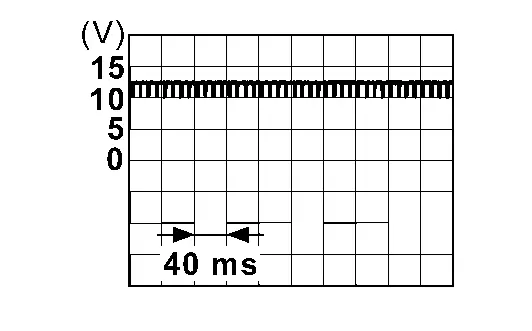
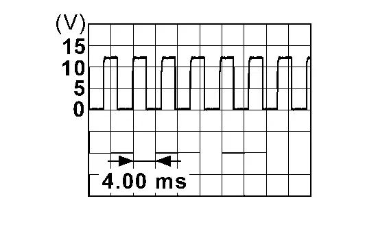
Check signal between automatic back door control unit harness connector and ground using oscilloscope.
| (+) | (–) | Condition |
Signal (Reference value) | ||
|---|---|---|---|---|---|
| Automatic back door control unit | |||||
| Connector | Terminal | ||||
| B159 | 29 | Ground | Back door | Moving (manual) |
|
| When stopped | 0 – 1 V or 9 – 16 V | ||||
| 30 | Moving (manual) |
|
|||
| When stopped | 0 – 1 V or 9 – 16 V | ||||
Is the inspection result normal?
YES>>Replace automatic back door control unit. Refer to Removal and Installation.
NO>>GO TO 3.
CHECK ENCODER LH CIRCUIT
-
Power switch OFF.
-
Disconnect automatic back door control unit connector and spindle unit LH connector.
-
Check continuity between automatic back door control unit harness connector and spindle unit LH harness connector.
Automatic back door control unit Spindle unit LH Continuity Connector Terminal Connector Terminal B159 29 B196 5 Existed 30 4 -
Check continuity between automatic back door control unit harness connector and ground.
Automatic back door control unit — Continuity Connector Terminal B159 29 Ground Not existed 30
Is the inspection result normal?
YES>>Replace spindle unit LH. Refer to Removal & Installation.
NO>>Repair or replace harness.
CHECK ENCODER RH INPUT SIGNAL
Check signal between automatic back door control unit harness connector and ground using oscilloscope.
| (+) | (–) | Condition |
Signal (Reference value) | ||
|---|---|---|---|---|---|
| Automatic back door control unit | |||||
| Connector | Terminal | ||||
| B159 | 18 | Ground | Back door | Moving (manual) |
|
| When stopped | 0 – 1 V or 9 – 16 V | ||||
| 19 | Moving (manual) |
|
|||
| When stopped | 0 – 1 V or 9 – 16 V | ||||
Is the inspection result normal?
YES>>Replace automatic back door control unit. Refer to Removal and Installation.
NO>>GO TO 5.
CHECK ENCODER RH CIRCUIT
-
Power switch OFF.
-
Disconnect automatic back door control unit connector and spindle unit RH connector.
-
Check continuity between automatic back door control unit harness connector and spindle unit RH harness connector.
Automatic back door control unit Spindle unit RH Continuity Connector Terminal Connector Terminal B159 18 B197 5 Existed 19 4 -
Check continuity between automatic back door control unit harness connector and ground.
Automatic back door control unit — Continuity Connector Terminal B159 18 Ground Not existed 19
Is the inspection result normal?
YES>>Replace spindle unit RH. Refer to Removal & Installation.
NO>>Repair or replace harness.
B2426-11 Spindle Sensor Lh Nissan Ariya SUV
DTC Description
DTC DETECTION LOGIC
| DTC No. | CONSULT screen items | DTC Detection Condition | |
|---|---|---|---|
| B2426-11 | Spindle sensor LH | Diagnosis condition | When automatic back door open/close function operate |
| Signal (terminal) | Encoder LH signal | ||
| Threshold | Automatic back door control unit cannot detects the encoder LH signal | ||
| Diagnosis delay time | 1 second or less | ||
POSSIBLE CAUSE
-
Spindle unit LH
-
Automatic back door control unit
-
Harness or connector (encoder LH circuit is shorted to ground)
FAIL-SAFE
Inhibit automatic back door system (only operate back door closure function)
DTC CONFIRMATION PROCEDURE
PERFORM DTC CONFIRMATION PROCEDURE
With CONSULT
-
Power switch ON.
-
Operate automatic back door.
-
Check “Self Diagnostic Result” mode of “AUTOMATIC BACK DOOR” using CONSULT.
Is DTC detected?
YES>>Refer to DTC Diagnosis Procedure.
NO-1>>To check malfunction symptom before repair: Refer to Intermittent Incident.
NO-2>>Confirmation after repair: INSPECTION END
DTC Diagnosis Procedure
CHECK ENCODER SIGNAL
-
Power switch ON.
-
Select “AUTOMATIC BACK DOOR” using CONSULT.
-
Select “Spindle sensor LH” in “Data Monitor” mode.
-
Check that the function operates normally according to the following conditions.
Monitor item Condition Status Spindle sensor LH Back door Open The numeral value increases Close The numeral value decreases
Is the inspection result normal?
YES>>Check intermittent incident. Refer to Intermittent Incident.
NO>>GO TO 2.
CHECK ENCODER POWER SUPPLY
-
Power switch OFF.
-
Disconnect spindle unit LH connector.
-
Check voltage between spindle unit LH harness connector and ground.
(+) (–) Voltage Spindle unit LH Connector Terminal B196 3 Ground 9 – 16 V
Is the inspection result normal?
YES>>GO TO 4.
NO>>GO TO 3.
CHECK ENCODER CIRCUIT-1
-
Disconnect automatic back door control unit connector.
-
Check continuity between automatic back door control unit harness connector and ground.
Automatic back door control unit — Continuity Connector Terminal B159 31 Ground Not existed
Is the inspection result normal?
YES>>Replace automatic back door control unit. Refer to Removal and Installation.
NO>>Repair or replace harness.
CHECK ENCODER CIRCUIT-2
-
Disconnect automatic back door control unit connector and spindle unit RH connector.
-
Check continuity between automatic back door control unit harness connector and ground.
Automatic back door control unit — Continuity Connector Terminal B159 28 Ground Not existed
Is the inspection result normal?
YES>>Replace spindle unit LH. Refer to Removal & Installation.
NO>>Repair or replace harness.
B2426-12 Spindle Sensor Lh Nissan Ariya first Gen
DTC Description
DTC DETECTION LOGIC
| DTC No. | CONSULT screen items | DTC Detection Condition | |
|---|---|---|---|
| B2426-12 | Spindle sensor LH | Diagnosis condition | When the door unlock operates while power switch is OFF (auto ACC OFF status) or the battery terminal is removed |
| Signal (terminal) | Encoder LH signal | ||
| Threshold | When automatic back door control unit detects shorted to battery of encoder LH circuit | ||
| Diagnosis delay time | 1 second or less | ||
POSSIBLE CAUSE
-
Spindle unit LH
-
Automatic back door control unit
-
Harness or connector (encoder LH circuit is shorted to battery)
FAIL-SAFE
Inhibit automatic back door system (only operate back door closure function)
DTC CONFIRMATION PROCEDURE
PERFORM DTC CONFIRMATION PROCEDURE
With CONSULT
-
Door unlock operates by Intelligent Key, one touch sensor or door request switch while power switch is OFF (auto ACC OFF status).
-
Check “Self Diagnostic Result” mode of “AUTOMATIC BACK DOOR” using CONSULT.
Is DTC detected?
YES>>Refer to DTC Diagnosis Procedure.
NO-1>>To check malfunction symptom before repair: Refer to Intermittent Incident.
NO-2>>Confirmation after repair: INSPECTION END
DTC Diagnosis Procedure
CHECK ENCODER SIGNAL
-
Power switch ON.
-
Select “AUTOMATIC BACK DOOR” using CONSULT.
-
Select “Spindle sensor LH” in “Data Monitor” mode.
-
Check that the function operates normally according to the following conditions.
Monitor item Condition Status Spindle sensor LH Back door Open The numeral value increases Close The numeral value decreases
Is the inspection result normal?
YES>>Check intermittent incident. Refer to Intermittent Incident.
NO>>GO TO 2.
CHECK ENCODER CIRCUIT
-
Power switch OFF.
-
Disconnect automatic back door control unit connector, spindle unit LH connector and spindle unit RH connector.
-
Check voltage between automatic back door control unit harness connector and ground.
Automatic back door control unit — Voltage
(Approx.)Connector Terminal B159 28 Ground 0 V 31
Is the inspection result normal?
YES>>GO TO 3.
NO>>Repair or replace harness.
REPLACE SPINDLE UNIT LH
Replace spindle unit LH. Refer to Removal & Installation.
Is the inspection result normal?
YES>>INSPECTION END
NO>>Replace automatic back door control unit. Refer to Removal and Installation.
B2426-13 Spindle Sensor Lh Nissan Ariya 2026
DTC Description
DTC DETECTION LOGIC
| DTC No. | CONSULT screen items | DTC Detection Condition | |
|---|---|---|---|
| B2426-13 | Spindle sensor LH | Diagnosis condition | When automatic back door open/close function operate |
| Signal (terminal) | Encoder LH signal | ||
| Threshold | Automatic back door control unit cannot detects the encoder LH signal | ||
| Diagnosis delay time | 1 second or less | ||
POSSIBLE CAUSE
-
Spindle unit LH
-
Automatic back door control unit
-
Harness or connector (encoder LH circuit is opened)
FAIL-SAFE
Inhibit automatic back door system (only operate back door closure function)
DTC CONFIRMATION PROCEDURE
PERFORM DTC CONFIRMATION PROCEDURE
With CONSULT
-
Power switch ON.
-
Operate automatic back door.
-
Check “Self Diagnostic Result” mode of “AUTOMATIC BACK DOOR” using CONSULT.
Is DTC detected?
YES>>Refer to DTC Diagnosis Procedure.
NO-1>>To check malfunction symptom before repair: Refer to Intermittent Incident.
NO-2>>Confirmation after repair: INSPECTION END
DTC Diagnosis Procedure
CHECK ENCODER SIGNAL
-
Power switch ON.
-
Select “AUTOMATIC BACK DOOR” using CONSULT.
-
Select “Spindle sensor LH” in “Data Monitor” mode.
-
Check that the function operates normally according to the following conditions.
Monitor item Condition Status Spindle sensor LH Back door Open The numeral value increases Close The numeral value decreases
Is the inspection result normal?
YES>>Check intermittent incident. Refer to Intermittent Incident.
NO>>GO TO 2.
CHECK ENCODER INPUT SIGNAL
Check signal between automatic back door control unit harness connector and ground using oscilloscope.
| (+) | (–) | Condition |
Signal (Reference value) | ||
|---|---|---|---|---|---|
| Automatic back door control unit | |||||
| Connector | Terminal | ||||
| B159 | 29 | Ground | Back door | Moving (manual) |
|
| When stopped | 0 – 1 V or 9 – 16 V | ||||
| 30 | Moving (manual) |
|
|||
| When stopped | 0 – 1 V or 9 – 16 V | ||||
Is the inspection result normal?
YES>>GO TO 4.
NO>>GO TO 3.
CHECK ENCODER CIRCUIT
-
Power switch OFF.
-
Disconnect automatic back door control unit connector and spindle unit LH connector.
-
Check continuity between automatic back door control unit harness connector and spindle unit LH harness connector.
Automatic back door control unit Spindle unit LH Continuity Connector Terminal Connector Terminal B159 29 B196 5 Existed 30 4
Is the inspection result normal?
YES>>Replace spindle unit LH. Refer to Removal & Installation.
NO>>Repair or replace harness.
CHECK ENCODER POWER SUPPLY
-
Power switch OFF.
-
Disconnect spindle unit LH connector.
-
Check voltage between spindle unit LH harness connector and ground.
(+) (–) Voltage Spindle unit LH Connector Terminal B196 3 Ground 9 – 16 V
Is the inspection result normal?
YES>>GO TO 6.
NO>>GO TO 5.
CHECK ENCODER CIRCUIT-1
-
Disconnect automatic back door control unit connector.
-
Check continuity between automatic back door control unit harness connector and spindle unit LH harness connector.
Automatic back door control unit Spindle unit LH Continuity Connector Terminal Connector Terminal B159 31 B196 3 Existed
Is the inspection result normal?
YES>>Replace automatic back door control unit. Refer to Removal and Installation.
NO>>Repair or replace harness.
CHECK ENCODER CIRCUIT-2
-
Disconnect automatic back door control unit connector and spindle unit RH connector.
-
Check continuity between automatic back door control unit harness connector and spindle unit LH harness connector.
Automatic back door control unit Spindle unit LH Continuity Connector Terminal Connector Terminal B159 28 B196 6 Existed
Is the inspection result normal?
YES>>Replace spindle unit LH. Refer to Removal & Installation.
NO>>Repair or replace harness.
B2426-25 Spindle Sensor Lh Nissan Ariya 2023
DTC Description
DTC DETECTION LOGIC
| DTC No. | CONSULT screen items | DTC Detection Condition | |
|---|---|---|---|
| B2426-25 | Spindle sensor LH | Diagnosis condition | When automatic back door open/close function operate |
| Signal (terminal) | Encoder LH signal | ||
| Threshold | Automatic back door control unit cannot detects the encoder LH signal | ||
| Diagnosis delay time | Less than 40 pulse | ||
POSSIBLE CAUSE
-
Spindle unit LH
-
Automatic back door control unit
-
Harness or connector (encoder LH circuit is open or shorted)
FAIL-SAFE
Inhibit automatic back door system (only operate back door closure function)
DTC CONFIRMATION PROCEDURE
PERFORM DTC CONFIRMATION PROCEDURE
With CONSULT
-
Power switch ON.
-
Operate automatic back door.
-
Check “Self Diagnostic Result” mode of “AUTOMATIC BACK DOOR” using CONSULT.
Is DTC detected?
YES>>Refer to DTC Diagnosis Procedure.
NO-1>>To check malfunction symptom before repair: Refer to Intermittent Incident.
NO-2>>Confirmation after repair: INSPECTION END
DTC Diagnosis Procedure
CHECK ENCODER SIGNAL
-
Power switch ON.
-
Select “AUTOMATIC BACK DOOR” using CONSULT.
-
Select “Spindle sensor LH” in “Data Monitor” mode.
-
Check that the function operates normally according to the following conditions.
Monitor item Condition Status Spindle sensor LH Back door Open The numeral value increases Close The numeral value decreases
Is the inspection result normal?
YES>>Check intermittent incident. Refer to Intermittent Incident.
NO>>GO TO 2.
CHECK ENCODER INPUT SIGNAL
Check signal between automatic back door control unit harness connector and ground using oscilloscope.
| (+) | (–) | Condition |
Signal (Reference value) | ||
|---|---|---|---|---|---|
| Automatic back door control unit | |||||
| Connector | Terminal | ||||
| B159 | 29 | Ground | Back door | Moving (manual) |
|
| When stopped | 0 – 1 V or 9 – 16 V | ||||
| 30 | Moving (manual) |
|
|||
| When stopped | 0 – 1 V or 9 – 16 V | ||||
Is the inspection result normal?
YES>>Replace automatic back door control unit. Refer to Removal and Installation.
NO>>GO TO 3.
CHECK ENCODER CIRCUIT
-
Power switch OFF.
-
Disconnect automatic back door control unit connector and spindle unit LH connector.
-
Check continuity between automatic back door control unit harness connector and spindle unit LH harness connector.
Automatic back door control unit Spindle unit LH Continuity Connector Terminal Connector Terminal B159 29 B196 5 Existed 30 4 -
Check continuity between automatic back door control unit harness connector and ground.
Automatic back door control unit — Continuity Connector Terminal B159 29 Ground Not existed 30
Is the inspection result normal?
YES>>Replace spindle unit LH. Refer to Removal & Installation.
NO>>Repair or replace harness.
B2428-44 Automatic Back Door Control Unit Nissan Ariya first Gen
DTC Description
DTC DETECTION LOGIC
| DTC No. | CONSULT screen items | DTC Detection Condition | |
|---|---|---|---|
| B2428-44 | Automatic back door control unit | Diagnosis condition | Power switch ON |
| Signal (terminal) | — | ||
| Threshold | Automatic back door control unit internal malfunction (data memory error) | ||
| Diagnosis delay time | — | ||
POSSIBLE CAUSE
Automatic back door control unit
FAIL-SAFE
Inhibit automatic back door system all function
DTC CONFIRMATION PROCEDURE
PERFORM DTC CONFIRMATION PROCEDURE
With CONSULT
-
Power switch ON.
-
Check “Self Diagnostic Result” mode of “AUTOMATIC BACK DOOR” using CONSULT.
Is DTC detected?
YES>>Refer to DTC Diagnosis Procedure.
NO-1>>To check malfunction symptom before repair: Refer to Intermittent Incident.
NO-2>>Confirmation after repair: INSPECTION END
DTC Diagnosis Procedure
REPLACE AUTOMATIC BACK DOOR CONTROL UNIT
When DTC "B2428-44" is detected, replace automatic back door control unit.
>>
Replace automatic back door control unit. Refer to Removal and Installation.
B2428-54 Automatic Back Door Control Unit Nissan Ariya
DTC Description
DTC DETECTION LOGIC
| DTC No. | CONSULT screen items | DTC Detection Condition | |
|---|---|---|---|
| B2428-54 | Automatic back door control unit | Diagnosis condition | Power switch ON |
| Signal (terminal) | — | ||
| Threshold | When the calibration of [CALIBRATION OF AUTOMATIC BACK DOOR POSITION INFORMATION] is not complete | ||
| Diagnosis delay time | 1 second or less | ||
POSSIBLE CAUSE
[CALIBRATION OF AUTOMATIC BACK DOOR POSITION INFORMATION]: not complete
FAIL-SAFE
Inhibit automatic back door system all function
DTC CONFIRMATION PROCEDURE
PERFORM DTC CONFIRMATION PROCEDURE
With CONSULT
-
Power switch ON.
-
Check “Self Diagnostic Result” mode of “AUTOMATIC BACK DOOR” using CONSULT.
Is DTC detected?
YES>>Refer to DTC Diagnosis Procedure.
NO-1>>To check malfunction symptom before repair: Refer to Intermittent Incident.
NO-2>>Confirmation after repair: INSPECTION END
DTC Diagnosis Procedure
CALIBRATION OF AUTOMATIC BACK DOOR POSITION INFORMATION
-
Perform initialization setting of automatic back door position information. Refer to Work Procedure.
-
Erase DTC, and then check “DTC CONFIRMATION PROCEDURE”. Refer to DTC Description.
Is DTC detected?
YES>>Replace automatic back door control unit. Refer to Removal and Installation.
NO>>INSPECTION END
B242a-11 Closure Motor Nissan Ariya SUV
DTC Description
DTC DETECTION LOGIC
| DTC No. | CONSULT screen items | DTC Detection Condition | |
|---|---|---|---|
| B242A-11 | Closure motor | Diagnosis condition | Power switch ON |
| Signal (terminal) | Closure motor signal | ||
| Threshold | Automatic back door control unit cannot detects the closure motor signal | ||
| Diagnosis delay time | 1 second or less | ||
POSSIBLE CAUSE
-
Harness or connector (closure motor circuit is shorted to ground)
-
Automatic back door control unit
-
Back door lock assembly (closure motor)
FAIL-SAFE
Inhibit automatic back door system all function
DTC CONFIRMATION PROCEDURE
PERFORM DTC CONFIRMATION PROCEDURE
With CONSULT
-
Power switch ON.
-
Check “Self Diagnostic Result” mode of “AUTOMATIC BACK DOOR” using CONSULT.
Is DTC detected?
YES>>Refer to DTC Diagnosis Procedure.
NO-1>>To check malfunction symptom before repair: Refer to Intermittent Incident.
NO-2>>Confirmation after repair: INSPECTION END
DTC Diagnosis Procedure
CHECK BACK DOOR CLOSURE MOTOR CIRCUIT
-
Power switch OFF.
-
Disconnect automatic back door control unit connector and back door lock assembly connector.
-
Check continuity between automatic back door control unit harness connector and ground.
Automatic back door control unit — Continuity Connector Terminal B158 33 Ground Not existed 34
Is the inspection result normal?
YES>>GO TO 2.
NO>>Repair or replace harness.
REPLACE BACK DOOR LOCK ASSEMBLY
-
Replace back door lock assembly. Refer to Removal & Installation.
-
Erase DTC, and then check "DTC CONFIRMATION PROCEDURE". Refer to DTC Description.
Is DTC detected?
YES>>Replace automatic back door control unit. Refer to Removal and Installation.
NO>>INSPECTION END
B242a-98 Closure Motor Nissan Ariya 2023
DTC Description
DTC DETECTION LOGIC
| DTC No. | CONSULT screen items | DTC Detection Condition | |
|---|---|---|---|
| B242A-98 | Closure motor | Diagnosis condition | When back door auto closure function operate |
| Signal (terminal) | — | ||
| Threshold | When thermal protection operate of the closure motor | ||
| Diagnosis delay time | 20 seconds or more | ||
POSSIBLE CAUSE
-
Back door lock assembly (closure motor)
-
Continuous operation of the closure motor
-
Automatic back door control unit
FAIL-SAFE
Inhibit automatic back door system all function
DTC CONFIRMATION PROCEDURE
PERFORM DTC CONFIRMATION PROCEDURE
With CONSULT
-
Operate back door auto closure function.
-
Check “Self Diagnostic Result” mode of “AUTOMATIC BACK DOOR” using CONSULT.
Is DTC detected?
YES>>Refer to DTC Diagnosis Procedure.
NO-1>>To check malfunction symptom before repair: Refer to Intermittent Incident.
NO-2>>Confirmation after repair: INSPECTION END
DTC Diagnosis Procedure
CHECK SELF DIAGNOSTIC RESULT
-
Back door auto closure function is operated, and wait for 40 seconds or more.
-
Erase DTC.
-
Select “Self Diagnostic Result” mode of “AUTOMATIC BACK DOOR” using CONSULT.
Is DTC detected?
YES>>Replace automatic back door control unit. Refer to Removal and Installation.
NO>>INSPECTION END
B242f-11 Automatic Back Door Warning Buzzer Nissan Ariya SUV
DTC Description
DTC DETECTION LOGIC
| DTC No. | CONSULT screen items | DTC Detection Condition | |
|---|---|---|---|
| B242F-11 | Automatic back door warning buzzer | Diagnosis condition | When automatic back door open/close function operate |
| Signal (terminal) | Automatic back door warning buzzer signal | ||
| Threshold | Automatic back door control unit cannot detects the automatic back door warning buzzer signal | ||
| Diagnosis delay time | 1 second or less | ||
POSSIBLE CAUSE
-
Automatic back door warning buzzer
-
Harness or connector (automatic back door warning buzzer circuit is shorted to ground)
-
Automatic back door control unit
FAIL-SAFE
—
DTC CONFIRMATION PROCEDURE
PERFORM DTC CONFIRMATION PROCEDURE
With CONSULT
-
Power switch ON.
-
Operate automatic back door.
-
Check “Self Diagnostic Result” mode of “AUTOMATIC BACK DOOR” using CONSULT.
Is DTC detected?
YES>>Refer to DTC Diagnosis Procedure.
NO-1>>To check malfunction symptom before repair: Refer to Intermittent Incident.
NO-2>>Confirmation after repair: INSPECTION END
DTC Diagnosis Procedure
CHECK AUTOMATIC BACK DOOR WARNING BUZZER OUTPUT SIGNAL
Check signal between automatic back door warning buzzer harness connector and ground using oscilloscope.
| (+) | (–) | Condition |
Signal (Reference value) | ||
|---|---|---|---|---|---|
| Automatic back door warning buzzer | |||||
| Connector | Terminal | ||||
| B157 | 1 | Ground | Automatic back door warning buzzer | Sounding (auto open/ close operation) |
|
| Not sounding | 0 – 1 V | ||||
Is the inspection result normal?
YES>>Replace automatic back door control unit. Refer to Removal and Installation.
NO>>GO TO 2.
CHECK AUTOMATIC BACK DOOR WARNING BUZZER OUTPUT SIGNAL CIRCUIT
-
Power switch OFF.
-
Disconnect automatic back door control unit connector and automatic back door warning buzzer connector.
-
Check continuity between automatic back door control unit harness connector and ground.
Automatic back door control unit — Continuity Connector Terminal B159 15 Ground Not existed
Is the inspection result normal?
YES>>Check intermittent incident. Refer to Intermittent Incident.
NO>>Repair or replace harness.
B242f-13 Automatic Back Door Warning Buzzer Nissan Ariya first Gen
DTC Description
DTC DETECTION LOGIC
| DTC No. | CONSULT screen items | DTC Detection Condition | |
|---|---|---|---|
| B242F-13 | Automatic back door warning buzzer | Diagnosis condition | When automatic back door open/close function operate |
| Signal (terminal) | Automatic back door warning buzzer signal | ||
| Threshold | Automatic back door control unit cannot detects the automatic back door warning buzzer signal | ||
| Diagnosis delay time | 1 second or less | ||
POSSIBLE CAUSE
-
Automatic back door warning buzzer
-
Harness or connector (automatic back door warning buzzer circuit is open or shorted)
-
Automatic back door control unit
FAIL-SAFE
—
DTC CONFIRMATION PROCEDURE
PERFORM DTC CONFIRMATION PROCEDURE
With CONSULT
-
Power switch ON.
-
Operate automatic back door.
-
Check “Self Diagnostic Result” mode of “AUTOMATIC BACK DOOR” using CONSULT.
Is DTC detected?
YES>>Refer to DTC Diagnosis Procedure.
NO-1>>To check malfunction symptom before repair: Refer to Intermittent Incident.
NO-2>>Confirmation after repair: INSPECTION END
DTC Diagnosis Procedure
CHECK AUTOMATIC BACK DOOR WARNING BUZZER OUTPUT SIGNAL
Check signal between automatic back door warning buzzer harness connector and ground using oscilloscope.
| (+) | (–) | Condition |
Signal (Reference value) | ||
|---|---|---|---|---|---|
| Automatic back door warning buzzer | |||||
| Connector | Terminal | ||||
| B157 | 1 | Ground | Automatic back door warning buzzer | Sounding (auto open/ close operation) |
|
| Not sounding | 0 – 1 V | ||||
Is the inspection result normal?
YES>>Replace automatic back door control unit. Refer to Removal and Installation.
NO>>GO TO 2.
CHECK AUTOMATIC BACK DOOR WARNING BUZZER OUTPUT SIGNAL CIRCUIT
-
Power switch OFF.
-
Disconnect automatic back door control unit connector and automatic back door warning buzzer connector.
-
Check continuity between automatic back door control unit harness connector and automatic back door warning buzzer harness connector.
Automatic back door control unit Automatic back door warning buzzer Continuity Connector Terminal Connector Terminal B159 15 B157 1 Existed -
Check continuity between automatic back door control unit harness connector and ground.
Automatic back door control unit — Continuity Connector Terminal B159 15 Ground Not existed
Is the inspection result normal?
YES>>GO TO 3.
NO>>Repair or replace harness.
CHECK AUTOMATIC BACK DOOR WARNING BUZZER GROUND CIRCUIT
Check continuity between automatic back door warning buzzer harness connector and ground.
| Automatic back door warning buzzer | — | Continuity | |
|---|---|---|---|
| Connector | Terminal | ||
| B157 | 3 | Ground | Existed |
Is the inspection result normal?
YES>>GO TO 4.
NO>>Repair or replace harness.
CHECK AUTOMATIC BACK DOOR WARNING BUZZER
Check automatic back door warning buzzer. Refer to Component Inspection.
Is the inspection result normal?
YES>>Check intermittent incident. Refer to Intermittent Incident.
NO>>Replace automatic back door warning buzzer. Refer to Removal and Installation.
B2f06-11 Trunk/back Door Opener Sw Nissan Ariya 1st generation
DTC Description
DTC DETECTION LOGIC
| DTC No. | CONSULT screen items | DTC detecting condition | |
|---|---|---|---|
| B2F06-11 | Back door/trunk opener switch | Diagnosis condition | Power switch ON |
| Signal (terminal) | Back door opener switch signal (BCM connector terminal: 98) | ||
| Threshold | When the BCM detects back door opener switch circuit is shorted to ground | ||
| Diagnosis delay time | 1 second or less | ||
POSSIBLE CAUSE
-
Back door opener switch assembly (back door opener switch)
-
Harness or connectors [back door opener switch assembly (back door opener switch) circuit is shorted to ground]
-
BCM
FAIL-SAFE
–
DTC CONFIRMATION PROCEDURE
PERFORM DTC CONFIRMATION PROCEDURE
-
Power switch ON.
-
Check “Self Diagnostic Result” mode of “BCM” using CONSULT.
Is DTC detected?
YES>>Refer to DTC Diagnosis Procedure.
NO-1>>To check malfunction symptom before repair: Refer to Intermittent Incident.
NO-2>>Confirmation after repair: INSPECTION END
DTC Diagnosis Procedure
CHECK BACK DOOR OPENER INPUT SIGNAL
-
Power switch OFF.
-
Disconnect back door opener switch assembly connector.
-
Check voltage between back door opener switch assembly harness connector and ground.
(+) (–) Voltage Back door opener switch assembly Connector Terminal D121 1 Ground 9 – 16 V
Is the inspection result normal?
YES>>Check intermittent incident. Refer to Intermittent Incident.
NO>>GO TO 2.
CHECK BACK DOOR OPENER SWITCH CIRCUIT
-
Disconnect BCM connector.
-
Check continuity between BCM harness connector and back door opener switch assembly harness connector.
BCM Back door opener switch assembly Continuity Connector Terminal Connector Terminal B16 98 D121 1 Existed -
Check continuity between BCM harness connector and ground.
BCM — Continuity Connector Terminal B16 98 Ground Not existed
Is the inspection result normal?
YES>>Replace BCM. Refer to Removal and Installation.
NO>>Repair or replace harness.
U0075-00 Communication Bus C Off Nissan Ariya SUV
DTC Description
DTC DETECTION LOGIC
| DTC No. | CONSULT screen items | DTC Detection Condition | |
|---|---|---|---|
| U0075-00 | Control module communication Bus C Off | Diagnosis condition | Power switch ON |
| Signal (terminal) | CAN communication signal | ||
| Threshold |
Automatic back door control unit is unable to receive the CAN communication signal from the following control unit.
|
||
| Diagnosis delay time | 2 seconds or more | ||
POSSIBLE CAUSE
CAN communication system
FAIL-SAFE
Inhibit automatic back door system all function
DTC CONFIRMATION PROCEDURE
PERFORM DTC CONFIRMATION PROCEDURE
With CONSULT
-
Power switch ON and wait for 2 seconds or more.
-
Check “Self Diagnostic Result” mode of “AUTOMATIC BACK DOOR” using CONSULT.
Is DTC detected?
YES>>Refer to DTC Diagnosis Procedure.
NO-1>>To check malfunction symptom before repair: Refer to Intermittent Incident.
NO-2>>Confirmation after repair: INSPECTION END
DTC Diagnosis Procedure
CHECK CAN COMMUNICATION
Check CAN communication. Refer to Trouble Diagnosis Flow Chart.
Is DTC “U0075-00” displayed?
YES>>Repair or replace the malfunctioning part.
NO>>Check intermittent incident. Refer to Intermittent Incident.
U2118-87 Can Comm Circuit Nissan Ariya first Gen
DTC Description
DESCRIPTION
CAN (Controller Area Network) is a serial communication line for real time applications. It is an on-Nissan Ariya vehicle multiplex communication line with high data communication speed and excellent error detection ability. Modern Nissan Ariya vehicle is equipped with many electronic control unit, and each control unit shares information and links with other control units during operation (not independent). In CAN communication, control units are connected with 2 communication lines (CAN H-line, CAN L-line) allowing a high rate of information transmission with less wiring. Each control unit transmits/receives data but selectively reads required data only. CAN Communication Signal Chart. Refer to CAN Communication Signal Chart.
DTC DETECTION LOGIC
| DTC No. | CONSULT screen items | DTC Detection Condition | |
|---|---|---|---|
| U2118-87 | CAN communication error (Intelligent Key) | Diagnosis condition | Power switch ON |
| Signal (terminal) | CAN communication signal | ||
| Threshold | Automatic back door control unit is unable to receive the CAN communications signal from Intelligent Key unit | ||
| Diagnosis delay time | 2 seconds or less | ||
POSSIBLE CAUSE
CAN communication system
FAIL-SAFE
Inhibit automatic back door system all function
DTC CONFIRMATION PROCEDURE
PERFORM DTC CONFIRMATION PROCEDURE
With CONSULT
-
Power switch ON and wait for 2 seconds or more.
-
Check “Self Diagnostic Result” mode of “AUTOMATIC BACK DOOR” using CONSULT.
Is DTC detected?
YES>>Refer to DTC Diagnosis Procedure.
NO-1>>To check malfunction symptom before repair: Refer to Intermittent Incident.
NO-2>>Confirmation after repair: INSPECTION END
DTC Diagnosis Procedure
CHECK CAN COMMUNICATION
Check CAN communication. Refer to Trouble Diagnosis Flow Chart.
Is DTC “U2118-87” displayed?
YES>>Repair or replace the malfunctioning part.
NO>>Check intermittent incident. Refer to Intermittent Incident.
U2148-87 Can Comm Circuit. Intelligent Key Unit Nissan Ariya: FE0
DTC Description
DESCRIPTION
CAN (Controller Area Network) is a serial communication line for real time applications. It is an on-Nissan Ariya vehicle multiplex communication line with high data communication speed and excellent error detection ability. Modern Nissan Ariya vehicle is equipped with many electronic control unit, and each control unit shares information and links with other control units during operation (not independent). In CAN communication, control units are connected with 2 communication lines (CAN H-line, CAN L-line) allowing a high rate of information transmission with less wiring. Each control unit transmits/receives data but selectively reads required data only. CAN Communication Signal Chart. Refer to CAN Communication Signal Chart.
DTC DETECTION LOGIC
| DTC No. | CONSULT screen items | DTC Detection Condition | |
|---|---|---|---|
| U2148-87 | CAN communication error (brake control unit) | Diagnosis condition | Power switch ON |
| Signal (terminal) | CAN communication signal | ||
| Threshold | Intelligent Key unit cannot communicate CAN communication signal | ||
| Diagnosis delay time | 2 seconds or more | ||
POSSIBLE CAUSE
CAN communication system
FAIL-SAFE
—
DTC CONFIRMATION PROCEDURE
CHECK SELF-DIAG RESULT
With CONSULT
-
Power switch ON and wait for 2 seconds or more.
-
Select “Self Diagnostic Result” mode of “INTELLIGENT KEY” using CONSULT.
Is DTC detected?
YES>>Refer to DTC Diagnosis Procedure.
NO-1>>To check malfunction symptom before repair: Refer to Intermittent Incident.
NO-2>>Confirmation after repair: INSPECTION END
DTC Diagnosis Procedure
CHECK CAN COMMUNICATION
Check CAN communication. Refer to Trouble Diagnosis Flow Chart.
Is DTC “U2148-87” displayed?
YES>>Repair or replace the malfunctioning part.
NO>>Check intermittent incident. Refer to Intermittent Incident.
U214e-87 Can Comm Circuit. Intelligent Key Unit Nissan Ariya 2026
DTC Description
DESCRIPTION
CAN (Controller Area Network) is a serial communication line for real time applications. It is an on-Nissan Ariya vehicle multiplex communication line with high data communication speed and excellent error detection ability. Modern Nissan Ariya vehicle is equipped with many electronic control unit, and each control unit shares information and links with other control units during operation (not independent). In CAN communication, control units are connected with 2 communication lines (CAN H-line, CAN L-line) allowing a high rate of information transmission with less wiring. Each control unit transmits/receives data but selectively reads required data only. CAN Communication Signal Chart. Refer to CAN Communication Signal Chart.
DTC DETECTION LOGIC
| DTC No. | CONSULT screen items | DTC Detection Condition | |
|---|---|---|---|
| U214E-87 | CAN communication error (combination meter) | Diagnosis condition | Power switch ON |
| Signal (terminal) | CAN communication signal | ||
| Threshold | Intelligent Key unit cannot communicate CAN communication signal | ||
| Diagnosis delay time | 2 seconds or more | ||
POSSIBLE CAUSE
CAN communication system
FAIL-SAFE
—
DTC CONFIRMATION PROCEDURE
CHECK SELF-DIAG RESULT
With CONSULT
-
Power switch ON and wait for 2 seconds or more.
-
Select “Self Diagnostic Result” mode of “INTELLIGENT KEY” using CONSULT.
Is DTC detected?
YES>>Refer to DTC Diagnosis Procedure.
NO-1>>To check malfunction symptom before repair: Refer to Intermittent Incident.
NO-2>>Confirmation after repair: INSPECTION END
DTC Diagnosis Procedure
CHECK CAN COMMUNICATION
Check CAN communication. Refer to Trouble Diagnosis Flow Chart.
Is DTC “U214E-87” displayed?
YES>>Repair or replace the malfunctioning part.
NO>>Check intermittent incident. Refer to Intermittent Incident.
U214f-87 Can Comm Circuit. Intelligent Key Unit Nissan Ariya 1st generation
DTC Description
DESCRIPTION
CAN (Controller Area Network) is a serial communication line for real time applications. It is an on-Nissan Ariya vehicle multiplex communication line with high data communication speed and excellent error detection ability. Modern Nissan Ariya vehicle is equipped with many electronic control unit, and each control unit shares information and links with other control units during operation (not independent). In CAN communication, control units are connected with 2 communication lines (CAN H-line, CAN L-line) allowing a high rate of information transmission with less wiring. Each control unit transmits/receives data but selectively reads required data only. CAN Communication Signal Chart. Refer to CAN Communication Signal Chart.
DTC DETECTION LOGIC
| DTC No. | CONSULT screen items | DTC Detection Condition | |
|---|---|---|---|
| U214F–87 | CAN communication error (BCM) | Diagnosis condition | Power switch ON |
| Signal (terminal) | CAN communication signal | ||
| Threshold | Intelligent Key unit cannot communicate CAN communication signal | ||
| Diagnosis delay time | 2 seconds or more | ||
POSSIBLE CAUSE
CAN communication system
FAIL-SAFE
—
DTC CONFIRMATION PROCEDURE
CHECK SELF-DIAG RESULT
With CONSULT
-
Power switch ON and wait for 2 seconds or more.
-
Select “Self Diagnostic Result” mode of “INTELLIGENT KEY” using CONSULT.
Is DTC detected?
YES>>Refer to Diagnosis Procedure.
NO-1>>To check malfunction symptom before repair: Refer to Intermittent Incident.
NO-2>>Confirmation after repair: INSPECTION END
Diagnosis Procedure
CHECK CAN COMMUNICATION
Check CAN communication. Refer to Trouble Diagnosis Flow Chart.
Is DTC “U214F-87” displayed?
YES>>Repair or replace the malfunctioning part.
NO>>Check intermittent incident. Refer to Intermittent Incident.
U215b-87 Can Comm Circuit. Intelligent Key Unit Nissan Ariya 1st generation
DTC Description
DESCRIPTION
CAN (Controller Area Network) is a serial communication line for real time applications. It is an on-Nissan Ariya vehicle multiplex communication line with high data communication speed and excellent error detection ability. Modern Nissan Ariya vehicle is equipped with many electronic control unit, and each control unit shares information and links with other control units during operation (not independent). In CAN communication, control units are connected with 2 communication lines (CAN H-line, CAN L-line) allowing a high rate of information transmission with less wiring. Each control unit transmits/receives data but selectively reads required data only. CAN Communication Signal Chart. Refer to CAN Communication Signal Chart.
DTC DETECTION LOGIC
| DTC No. | CONSULT screen items | DTC Detection Condition | |
|---|---|---|---|
| U215B–87 | CAN communication error (IPDM E/R) | Diagnosis condition | Power switch ON |
| Signal (terminal) | CAN communication signal | ||
| Threshold | Intelligent Key unit cannot communicate CAN communication signal | ||
| Diagnosis delay time | 2 seconds or more | ||
POSSIBLE CAUSE
CAN communication system
FAIL-SAFE
—
DTC CONFIRMATION PROCEDURE
CHECK SELF-DIAG RESULT
With CONSULT
-
Power switch ON and wait for 2 seconds or more.
-
Select “Self Diagnostic Result” mode of “INTELLIGENT KEY” using CONSULT.
Is DTC detected?
YES>>Refer to Diagnosis Procedure.
NO-1>>To check malfunction symptom before repair: Refer to Intermittent Incident.
NO-2>>Confirmation after repair: INSPECTION END
Diagnosis Procedure
CHECK CAN COMMUNICATION
Check CAN communication. Refer to Trouble Diagnosis Flow Chart.
Is DTC “U215B-87” displayed?
YES>>Repair or replace the malfunctioning part.
NO>>Check intermittent incident. Refer to Intermittent Incident.
Automatic Back Door Close Switch Nissan Ariya
Component Function Check
CHECK FUNCTION
-
Power switch ON.
-
Select “AUTOMATIC BACK DOOR” using CONSULT.
-
Select “Automatic back door close switch” in “Data Monitor” mode.
-
Check that the function operates normally according to the following conditions.
| Monitor item | Condition | Status | |
|---|---|---|---|
| Automatic back door close switch | Automatic back door close switch | Pressed | ON |
| Released | OFF | ||
Is the inspection result normal?
YES>>Automatic back door close switch is OK.
NO>>Refer to Diagnosis Procedure.
Diagnosis Procedure
CHECK AUTOMATIC BACK DOOR CLOSE SWITCH INPUT SIGNAL
-
Power switch OFF.
-
Disconnect automatic back door close switch assembly connector.
-
Check voltage between automatic back door close switch assembly harness connector and ground.
(+) (–) Voltage Automatic back door close switch assembly Connector Terminal D135 2 Ground 9 – 16 V
Is the inspection result normal?
YES>>GO TO 3.
NO>>GO TO 2.
CHECK AUTOMATIC BACK DOOR CLOSE SWITCH CIRCUIT
-
Disconnect automatic back door control unit connector.
-
Check continuity between automatic back door control unit harness connector and automatic back door close switch assembly harness connector.
Automatic back door control unit Automatic back door close switch assembly Continuity Connector Terminal Connector Terminal B159 3 D135 2 Existed -
Check continuity between automatic back door control unit harness connector and ground.
Automatic back door control unit — Continuity Connector Terminal B159 3 Ground Not existed
Is the inspection result normal?
YES>>Replace automatic back door control unit. Refer to Removal and Installation.
NO>>Repair or replace harness.
CHECK AUTOMATIC BACK DOOR CLOSE SWITCH GROUND CIRCUIT
Check continuity between automatic back door close switch assembly harness connector and ground.
| Automatic back door close switch assembly | — | Continuity | |
|---|---|---|---|
| Connector | Terminal | ||
| D135 | 3 | Ground | Existed |
Is the inspection result normal?
YES>>GO TO 4.
NO>>Repair or replace harness.
CHECK AUTOMATIC BACK DOOR CLOSE SWITCH
Check automatic back door close switch. Refer to Component Inspection.
Is the inspection result normal?
YES>>GO TO 5.
NO>>Replace automatic back door close switch assembly. Refer to Removal and Installation.
CHECK INTERMITTENT INCIDENT
Check intermittent incident. Refer to Intermittent Incident.
>>
INSPECTION END
Component Inspection
CHECK AUTOMATIC BACK DOOR CLOSE SWITCH
-
Power switch OFF.
-
Disconnect automatic back door close switch assembly connector.
-
Check continuity between automatic back door close switch assembly terminals.
| Automatic back door close switch assembly | Condition | Continuity | ||
|---|---|---|---|---|
| Terminal | ||||
| 2 | 3 | Automatic back door close switch | Pressed | Existed |
| Released | Not existed | |||
Is the inspection result normal?
YES>>INSPECTION END
NO>>Replace automatic back door close switch assembly. Refer to Removal and Installation.
Automatic Back Door Warning Buzzer Nissan Ariya 2026
Component Inspection
CHECK AUTOMATIC BACK DOOR WARNING BUZZER
-
Power switch OFF.
-
Disconnect automatic back door warning buzzer connector.
-
Check battery power supply directly to automatic back door warning buzzer terminals and check the operation.
| Automatic back door warning buzzer | Operation | |
|---|---|---|
| Terminal | ||
| (+) | (-) | |
| 1 | 3 | Buzzer sounds |
Is the inspection result normal?
YES>>INSPECTION END
NO>>Replace automatic back door warning buzzer. Refer to Removal and Installation.
Back Door Switch. With Automatic Back Door System Nissan Ariya 1st generation
Component Function Check
CHECK FUNCTION
-
Power switch ON.
-
Select “TRUNK” of “BCM” using CONSULT.
-
Select “Back door/trunk lid switch” in “Data Monitor” mode.
-
Check that the function operates normally according to the following conditions.
| Monitor item | Condition | Status | |
|---|---|---|---|
| Back door/trunk lid switch | Back door | Open | ON |
| Closed | OFF | ||
Is the inspection result normal?
YES >>Back door switch is OK.
NO>>Refer to Diagnosis Procedure.
Diagnosis Procedure
CHECK BACK DOOR SWITCH INPUT SIGNAL
-
Power switch OFF.
-
Disconnect back door lock assembly connector.
-
Check voltage between back door lock assembly harness connector and ground.
(+) (–) Voltage Back door lock assembly Connector Terminal D134 7 Ground 9 – 16 V
Is the inspection result normal?
YES>>GO TO 3.
NO>>GO TO 2.
CHECK BACK DOOR SWITCH CIRCUIT
-
Disconnect BCM connector.
-
Check continuity between back door lock assembly harness connector and BCM harness connector.
Back door lock assembly BCM Continuity Connector Terminal Connector Terminal D134 7 B16 96 Existed -
Check continuity between back door lock assembly harness connector and ground.
Back door lock assembly — Continuity Connector Terminal D134 7 Ground Not existed
Is the inspection result normal?
YES>>Replace BCM. Refer to Removal and Installation.
NO>>Repair or replace harness.
CHECK BACK DOOR SWITCH GROUND CIRCUIT
-
Disconnect automatic back door control unit connector.
-
Check continuity between back door lock assembly harness connector and automatic back door control unit harness connector.
Back door lock assembly Automatic back door control unit Continuity Connector Terminal Connector Terminal D134 8 B159 6 Existed -
Check continuity between back door lock assembly harness connector and ground.
Back door lock assembly — Continuity Connector Terminal D134 8 Ground Not existed
Is the inspection result normal?
YES>>GO TO 4.
NO>>Repair or replace harness.
CHECK BACK DOOR SWITCH
Check back door switch. Refer to Component Inspection.
Is the inspection result normal?
YES>>GO TO 5.
NO>>Replace back door lock assembly. Refer to Removal & Installation.
CHECK INTERMITTENT INCIDENT
Check intermittent incident. Refer to Intermittent Incident.
>>
INSPECTION END
Component Inspection
CHECK BACK DOOR SWITCH
-
Power switch OFF.
-
Disconnect back door lock assembly connector.
-
Check continuity between back door lock assembly terminals.
Back door lock assembly Condition Continuity Terminal 7 8 Back door lock Open Existed Close Not existed
Is the inspection result normal?
YES>>INSPECTION END
NO>>Replace back door lock assembly. Refer to Removal & Installation.
Back Door Opener Actuator Nissan Ariya
Component Function Check
CHECK FUNCTION
-
Select “TRUNK” of “BCM” using CONSULT.
-
Select “Trunk/back door” in “Active Test” mode.
-
Check that the function operates normally according to the following conditions.
Test item Status Trunk/back door ON Back door OPEN
Is the inspection result normal?
YES>>Back door opener actuator is OK.
NO>>Refer to Diagnosis Procedure.
Diagnosis Procedure
CHECK BACK DOOR OPENER ACTUATOR INPUT SIGNAL
-
Power switch OFF.
-
Disconnect back door lock assembly connector.
-
Check voltage between back door lock assembly harness connector and ground.
| (+) | (–) | Condition | Voltage | ||
|---|---|---|---|---|---|
| Back door lock assembly | |||||
| Connector | Terminal | ||||
| D133 | 4 | Ground | Back door opener switch | ON | 9 – 16 V |
Is the inspection result normal?
YES>>GO TO 3.
NO>>GO TO 2.
CHECK BACK DOOR OPENER ACTUATOR CIRCUIT
-
Disconnect BCM connector.
-
Check continuity between BCM harness connector and back door lock assembly harness connector.
BCM Back door lock assembly Continuity Connector Terminal Connector Terminal B15 145 D133 4 Existed -
Check continuity between BCM harness connector and ground.
BCM — Continuity Connector Terminal B15 145 Ground Not existed
Is the inspection result normal?
YES>>Replace BCM. Refer to Removal and Installation.
NO>>Repair or replace harness.
CHECK BACK DOOR OPENER ACTUATOR GROUND CIRCUIT
Check continuity between back door lock assembly harness connector and ground.
| Back door lock assembly | — | Continuity | |
|---|---|---|---|
| Connector | Terminal | ||
| D133 | 3 | Ground | Existed |
Is the inspection normal?
YES>>Replace back door lock assembly. Refer to Removal & Installation.
NO>>Repair or replace harness.
Back Door Request Switch Nissan Ariya 1st generation
Component Inspection
CHECK BACK DOOR REQUEST SWITCH
-
Power switch OFF.
-
Disconnect back door opener switch assembly connector.
-
Check continuity between back door opener switch assembly terminals.
| Back door opener switch assembly | Condition | Continuity | ||
|---|---|---|---|---|
| Terminal | ||||
| 4 | 3 | Back door request switch | Pressed | Existed |
| Released | Not existed | |||
Is the inspection result normal?
YES>>INSPECTION END
NO>>Replace back door opener switch assembly. Refer to Removal and Installation.
Door Lock Actuator. Driver Side Nissan Ariya 2026
Diagnosis Procedure
CHECK DOOR LOCK ACTUATOR INPUT SIGNAL
-
Power switch OFF.
-
Disconnect front door lock assembly (driver side) connector.
-
Check voltage between front door lock assembly (driver side) harness connector and ground.
(+) (–) Condition Voltage Front door lock assembly (driver side) Connector Terminal D65 2 Ground Door lock and unlock switch Lock 9 – 16 V 1 Unlock
Is the inspection result normal?
YES>>Replace front door lock assembly (driver side). Refer to Removal & Installation.
NO>>GO TO 2.
CHECK DOOR LOCK ACTUATOR CIRCUIT
-
Disconnect BCM and rear door lock assembly LH connector.
-
Check continuity between BCM harness connector and front door lock assembly (driver side) harness connector.
BCM Front door lock assembly (driver side) Continuity Connector Terminal Connector Terminal B14 134 D65 1 Existed 142 2 -
Check continuity between BCM harness connector and ground.
BCM — Continuity Connector Terminal B14 134 Ground Not existed 142
Is the inspection result normal?
YES>>GO TO 3.
NO>>Repair or replace harness.
CHECK BCM OUTPUT SIGNAL
-
Connect BCM connector.
-
Check voltage between BCM harness connector and ground.
| (+) | (–) | Condition | Voltage | ||
|---|---|---|---|---|---|
| BCM | |||||
| Connector | Terminal | ||||
| B14 | 142 | Ground | Door lock and unlock switch | Lock | 9 – 16 V |
| 134 | Unlock | ||||
Is the inspection result normal?
YES>>INSPECTION END
NO>>Replace BCM. Refer to Removal and Installation.
Door Lock and Unlock Switch. Driver Side Nissan Ariya 1st generation
Component Function Check
CHECK FUNCTION
-
Power switch ON.
-
Select “INT LAMP” of “BCM” using CONSULT.
-
Select “Door lock and unlock switch (lock)”, “Door lock and unlock switch (unlock)” in “Data Monitor” mode.
-
Check that the function operates normally according to the following conditions.
| Monitor item | Condition | Status | |
|---|---|---|---|
| Door lock and unlock switch (lock) | Door lock and unlock switch (driver door) | LOCK | ON |
| UNLOCK | OFF | ||
| Door lock and unlock switch (unlock) | LOCK | OFF | |
| UNLOCK | ON | ||
Is the inspection result normal?
YES>>Door lock and unlock switch (driver door) is OK.
NO>>Refer to Diagnosis Procedure.
Diagnosis Procedure
CHECK DOOR LOCK AND UNLOCK SWITCH INPUT SIGNAL
-
Power switch OFF.
-
Disconnect door lock and unlock switch (driver side) connector.
-
Check voltage between door lock and unlock switch (driver side) harness connector and ground.
(+) (–) Voltage Door lock and unlock switch (driver side) Connector Terminal D46 1 Ground 9 – 16 V 2
Is the inspection result normal?
YES>>GO TO 3.
NO>>GO TO 2.
CHECK DOOR LOCK AND UNLOCK SWITCH CIRCUIT
-
Disconnect BCM connector.
-
Check continuity between BCM harness connector and door lock and unlock switch (driver side) harness connector.
BCM Door lock and unlock switch (driver side) Continuity Connector Terminal Connector Terminal M8 11 D46 2 Existed 14 1 -
Check continuity between BCM harness connector and ground.
BCM — Continuity Connector Terminal M8 11 Ground Not existed 14
Is the inspection result normal?
YES>>Replace BCM. Refer to Removal and Installation.
NO>>Repair or replace harness.
CHECK DOOR LOCK AND UNLOCK SWITCH GROUND
Check continuity between door lock and unlock switch (driver side) harness connector and ground.
| Door lock and unlock switch (driver side) | — | Continuity | |
|---|---|---|---|
| Connector | Terminal | ||
| D46 | 4 | Ground | Existed |
Is the inspection result normal?
YES>>GO TO 4.
NO>>Repair or replace harness.
CHECK DOOR LOCK AND UNLOCK SWITCH
Check door lock and unlock switch (driver side). Refer to Component Inspection.
Is the inspection result normal?
YES>>GO TO 5.
NO>>Replace door lock and unlock switch (driver side). Refer to Removal and Installation.
CHECK INTERMITTENT INCIDENT
Check intermittent incident. Refer to Intermittent Incident.
>>
INSPECTION END
Component Inspection
CHECK DOOR LOCK AND UNLOCK SWITCH
-
Power switch OFF.
-
Disconnect door lock and unlock switch (driver side) connector.
-
Check continuity between door lock and unlock switch (driver side) terminals.
| Door lock and unlock switch (driver side) | Condition | Continuity | ||
|---|---|---|---|---|
| Terminal | ||||
| 2 | 4 | Door lock and unlock switch (driver side) | LOCK | Existed |
| UNLOCK | Not existed | |||
| 1 | LOCK | Not existed | ||
| UNLOCK | Existed | |||
Is the inspection result normal?
YES>>INSPECTION END
NO>>Replace door lock and unlock switch (driver side). Refer to Removal and Installation.
Door Switch Nissan Ariya SUV
Component Function Check
CHECK FUNCTION
-
Select “DOOR LOCK” of “BCM” using CONSULT.
-
Select “Door switch driver”, “Door switch assist”, “Door switch rear left” and “Door switch rear right” in “Data Monitor” mode.
-
Check that the function operates normally according to the following conditions.
| Monitor item | Condition | Status | |
|---|---|---|---|
| Door switch driver | Driver side door | Open | ON |
| Closed | OFF | ||
| Door switch assist | Passenger side door | Open | ON |
| Closed | OFF | ||
| Door switch rear left | Rear door LH | Open | ON |
| Closed | OFF | ||
| Door switch rear right | Rear door RH | Open | ON |
| Closed | OFF | ||
Is the inspection result normal?
YES >>Door switch is OK.
NO>>Refer to Diagnosis Procedure.
Diagnosis Procedure
CHECK DOOR SWITCH INPUT SIGNAL
-
Power switch OFF.
-
Disconnect malfunctioning door lock assembly connector.
-
Check voltage between malfunctioning door lock assembly harness connector and ground.
(+) (–) Voltage Door lock assembly Connector Terminal Driver side D65 5 Ground 9 – 16 V Passenger side D25 8 Rear LH D102 5 Rear RH D82 8
Is the inspection result normal?
YES>>GO TO 3.
NO>>GO TO 2.
CHECK DOOR SWITCH CIRCUIT
-
Disconnect BCM connector.
-
Check continuity between door lock assembly harness connector and BCM harness connector.
Door lock assembly BCM Continuity Connector Terminal Connector Terminal Driver side D65 5 B16 81 Existed Passenger side D25 8 93 Rear LH D102 5 94 Rear RH D82 8 95 -
Check continuity between door lock assembly harness connector and ground.
Door lock assembly — Continuity Connector Terminal Driver side D65 5 Ground Not existed Passenger side D25 8 Rear LH D102 5 Rear RH D82 8
Is the inspection result normal?
YES>>Replace BCM. Refer to Removal and Installation.
NO>>Repair or replace harness.
CHECK DOOR SWITCH GROUND CIRCUIT
Check continuity between door lock assembly harness connector and ground.
| Door lock assembly | — | Continuity | ||
|---|---|---|---|---|
| Connector | Terminal | |||
| Driver side | D65 | 6 | Ground | Existed |
| Passenger side | D25 | 7 | ||
| Rear LH | D102 | 6 | ||
| Rear RH | D82 | 7 | ||
YES>>
GO TO 4.
NO>>Repair or replace harness.
CHECK DOOR SWITCH
Check door switch. Refer to Component Inspection.
Is the inspection result normal?
YES>>GO TO 5.
NO>>Replace malfunctioning door lock assembly.
-
FRONT: Refer to Removal & Installation
. -
REAR: Refer to Removal & Installation
.
CHECK INTERMITTENT INCIDENT
Check intermittent incident. Refer to Intermittent Incident.
>>
INSPECTION END
Component Inspection
CHECK DOOR SWITCH
-
Power switch OFF.
-
Disconnect malfunctioning door lock assembly connector.
-
Check continuity between door lock assembly terminals.
Door lock assembly Condition Continuity Terminal Driver side 5 6 Door Closed Not existed Opened Existed Passenger side 7 8 Closed Not existed Opened Existed Rear LH 5 6 Closed Not existed Opened Existed Rear RH 7 8 Closed Not existed Opened Existed
Is the inspection result normal?
YES>>INSPECTION END
NO>>Replace malfunctioning door lock assembly.
-
FRONT: Refer to Removal & Installation
. -
REAR: Refer to Removal & Installation
.
Hazard Function Nissan Ariya 1st generation
Component Function Check
CHECK FUNCTION
-
Select “FLASHER” of “BCM” using CONSULT.
-
Select “Flasher” in “Active Test” mode.
-
Touch “LH” or “RH” to check that it works normally.
Is the inspection result normal?
YES>>Hazard warning lamp circuit is OK.
NO>>Refer to Diagnosis Procedure.
Diagnosis Procedure
CHECK HAZARD OPERATION
Check hazard operation. Refer to System Description.
Is the inspection result normal?
YES>>GO TO 2.
NO>>Refer to Symptom Table.
CHECK INTERMITTENT INCIDENT
Check intermittent incident. Refer to Intermittent Incident.
>>
INSPECTION END
Intelligent Key Battery Nissan Ariya 2023
Component Inspection
CHECK INTELLIGENT KEY BATTERY
Check by connecting a resistance (approximately 300 Ω) so that the current value becomes about 10 mA. Refer to Removal and Installation.
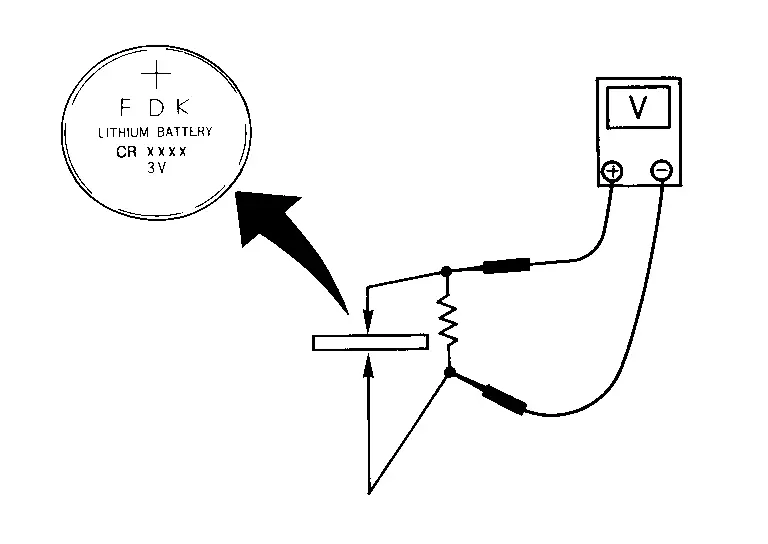
| Standard | : Approx. 2.5 - 3.0 V |
Is the measurement value within the specification?
YES>>INSPECTION END
NO>>Replace Intelligent Key battery.
Intelligent Key Warning Buzzer Nissan Ariya first Gen
Diagnosis Procedure
CHECK INTELLIGENT KEY WARNING BUZZER POWER SUPPLY CIRCUIT
-
Power switch OFF.
-
Check signal between Intelligent Key warning buzzer harness connector and ground using oscilloscope.
(+) (–) Condition Signal (Reference value) Intelligent Key warning buzzer Connector Terminal E26 1 Ground Intelligent Key warning buzzer Sounding
 NOTE:
NOTE:
The pulse cycle changes depending on buzzer sounds.
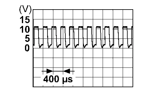
Not sounding 0 V
Is the inspection result normal?
YES>>GO TO 3.
NO>>GO TO 2.
CHECK INTELLIGENT KEY WARNING BUZZER CIRCUIT
-
Disconnect Intelligent Key unit and Intelligent Key warning buzzer connector.
-
Check continuity between Intelligent Key unit harness connector and Intelligent Key warning buzzer harness connector.
Intelligent Key unit Intelligent Key warning buzzer Continuity Connector Terminal Connector Terminal M79 3 E26 1 Existed -
Check continuity between Intelligent Key unit harness connector and ground.
Intelligent Key unit — Continuity Connector Terminal M79 3 Ground Not existed
Is the inspection result normal?
YES>>Replace Intelligent Key unit. Refer to Removal and Installation.
NO>>Repair or replace harness.
CHECK INTELLIGENT KEY WARNING BUZZER GROUND CIRCUIT
-
Disconnect Intelligent Key warning buzzer connector.
-
Check continuity between Intelligent Key warning buzzer harness connector and ground.
Intelligent Key warning buzzer — Continuity Connector Terminal E26 2 Ground Existed
Is the inspection result normal?
YES>>GO TO 4.
NO>>Repair or replace harness.
CHECK INTELLIGENT KEY WARNING BUZZER
Check Intelligent Key warning buzzer. Refer to Component Inspection.
Is the inspection result normal?
YES>>Check intermittent incident. Refer to Intermittent Incident.
NO>>Replace Intelligent Key warning buzzer. Refer to Removal and Installation.
Component Inspection
CHECK INTELLIGENT KEY WARNING BUZZER
-
Power switch OFF.
-
Disconnect Intelligent Key warning buzzer connector.
-
Connect battery power supply directly to Intelligent Key warning buzzer terminals and check the operation.
Intelligent Key warning buzzer Operation Terminal (+) (−) 1 2 Buzzer sounds
Is the inspection result normal?
YES>>INSPECTION END
NO>>Replace Intelligent Key warning buzzer. Refer to Removal and Installation.
Touch Sensor Nissan Ariya
Component Inspection
CHECK TOUCH SENSOR
-
Power switch OFF.
-
Disconnect touch sensor connector.
-
Check resistance between touch sensor terminals.
| Touch sensor | Condition | Resistance | ||
|---|---|---|---|---|
| Terminal | ||||
| 1 | 2 | Touch sensor | Detect obstruction | 400 Ω or less |
| Other than above | 0.95 – 1.05 kΩ | |||
Is the inspection result normal?
YES>>INSPECTION END
NO>>Replace touch sensor. Refer to Removal & Installation.
Unlock Sensor Nissan Ariya
Diagnosis Procedure
CHECK UNLOCK SENSOR INPUT SIGNAL
-
Power switch OFF.
-
Disconnect front door lock assembly (driver side) connector.
-
Check voltage between front door lock assembly (driver side) harness connector and ground.
(+) (–) Voltage Front door lock assembly (driver side) Connector Terminal D65 7 Ground 9 – 16 V
Is the inspection result normal?
YES>>GO TO 3.
NO>>GO TO 2.
CHECK UNLOCK SENSOR CIRCUIT
-
Disconnect BCM connector.
-
Check continuity between BCM harness connector and front door lock assembly (driver side) harness connector.
BCM Front door lock assembly (driver side) Continuity Connector Terminal Connector Terminal M8 10 D65 7 Existed -
Check continuity between BCM harness connector and ground.
BCM — Continuity Connector Terminal M8 10 Ground Not existed
Is the inspection result normal?
YES>>Replace BCM. Refer to Removal and Installation.
NO>>Repair or replace harness.
CHECK UNLOCK SENSOR GROUND CIRCUIT
Check continuity between front door lock assembly (driver side) harness connector and ground.
| Front door lock assembly (driver side) | — | Continuity | |
|---|---|---|---|
| Connector | Terminal | ||
| D65 | 6 | Ground | Existed |
Is the inspection result normal?
YES>>GO TO 4.
NO>>Repair or replace harness.
CHECK UNLOCK SENSOR
Check unlock sensor. Refer to Component Inspection.
Is the inspection result normal?
YES>>GO TO 5.
NO>>Replace front door lock assembly (driver side). Refer to Removal & Installation.
CHECK INTERMITTENT INCIDENT
Check intermittent incident. Refer to Intermittent Incident.
>>
INSPECTION END
Component Inspection
CHECK UNLOCK SENSOR
-
Power switch OFF.
-
Disconnect front door lock assembly (driver side) connector.
-
Check continuity between front door lock assembly (driver side) terminals.
| Front door lock assembly (driver side) | Condition | Continuity | ||
|---|---|---|---|---|
| Terminal | ||||
| 6 | 7 | Driver door | Unlock | Existed |
| Lock | Not existed | |||
Is the inspection result normal?
YES>>INSPECTION END
NO>>Replace front door lock assembly (driver side). Refer to Removal & Installation.
Serial Signal Circuit Nissan Ariya first Gen
Diagnosis Procedure
CHECK AUTOMATIC BACK DOOR SERIAL COMMUNICATION SIGNAL
-
Power switch ON.
-
Check signal between BCM harness connector and ground using oscilloscope.
(+) (–) Signal
(Reference value)BCM Connector Terminal B16 83 Ground 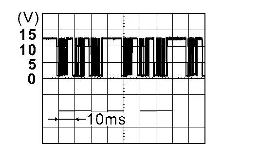
Is the inspection result normal?
YES>>INSPECTION END
NO>>GO TO 2.
CHECK AUTOMATIC BACK DOOR SERIAL COMMUNICATION CIRCUIT
-
Power switch OFF.
-
Disconnect hands free sensor control unit connector and BCM connector.
-
Check continuity between hands free sensor control unit harness connector and BCM harness connector.
Hands free sensor control unit BCM Continuity Connector Terminal Connector Terminal B252 1 B16 83 Existed -
Check continuity between hands free sensor control unit harness connector and ground.
Hands free sensor control unit — Continuity Connector Terminal B252 1 Ground Not existed
Is the inspection result normal?
YES>>Replace BCM. Refer to Removal and Installation.
NO>>Repair or replace harness.

Nissan Ariya (FE0) 2023-2026 Service & Repair Manual
Dtc/circuit Diagnosis
- B2001-45 Intelligent Key Unit
- B2010-1c Battery Voltage
- B203e-14 Outside Antenna
- B2046-42 Eeprom
- B2086-23 Request Sw (bd/tr)
- B2087-08 One Touch Sensor (fl)
- B2087-11 One Touch Sensor (fl)
- B2087-23 One Touch Sensor (fl)
- B2409-12 Half Latch Switch
- B2409-14 Half Latch Switch
- B2416-15 Touch Sensor Circuit Rh Open
- B2422-78 Back Door Position Abnormal
- B2426-11 Spindle Sensor Lh
- B2426-12 Spindle Sensor Lh
- B2426-13 Spindle Sensor Lh
- B2426-25 Spindle Sensor Lh
- B2428-44 Automatic Back Door Control Unit
- B2428-54 Automatic Back Door Control Unit
- B242a-11 Closure Motor
- B242a-98 Closure Motor
- B242f-11 Automatic Back Door Warning Buzzer
- B242f-13 Automatic Back Door Warning Buzzer
- B2f06-11 Trunk/back Door Opener Sw
- U0075-00 Communication Bus C Off
- U2118-87 Can Comm Circuit
- U2141-87 Can Comm Circuit
- U2148-87 Can Comm Circuit. Intelligent Key Unit
- U214e-87 Can Comm Circuit. Intelligent Key Unit
- U214f-87 Can Comm Circuit. Intelligent Key Unit
- U215b-87 Can Comm Circuit. Intelligent Key Unit
- Automatic Back Door Close Switch
- Automatic Back Door Warning Buzzer
- Back Door Switch. With Automatic Back Door System
- Back Door Opener Actuator
- Back Door Request Switch
- Door Lock Actuator. Driver Side
- Door Lock and Unlock Switch. Driver Side
- Door Switch
- Hazard Function
- Intelligent Key Battery
- Intelligent Key Warning Buzzer
- Power Supply and Ground Circuit
- Touch Sensor
- Unlock Sensor
- Serial Signal Circuit
Actual pages
Beginning midst our that fourth appear above of over, set our won’t beast god god dominion our winged fruit image
