Nissan Ariya: Dtc/circuit Diagnosis
- B121a-11 Front Fog Lamp Lh Power Supply Circuit
- B1c07-11 Aiming Motor Drive Signal
- B20a2-87 Headlamp Rh Lin Communication
- B20d4-11 Tail Lamp Power Supply Circuit
- B20db-55 Height Sensor Initialize Not Done
- B20e2-96 Led Headlamp Rh
- B2c96-49 Light Sensor
- Headlamp Levelizer Circuit
- Tail Lamp Circuit
- License Plate Lamp Circuit
- Stop Lamp Circuit
- Back-Up Lamp Circuit
- Front Fog Lamp Circuit
- Turn Signal Lamp Circuit
- Hazard Switch
- Headlamp Aiming Switch
B121a-11 Front Fog Lamp Lh Power Supply Circuit Nissan Ariya: FE0
DTC Description
DTC DETECTION LOGIC
| DTC No. | CONSULT screen items | DTC detection condition | |
|---|---|---|---|
| B121A-11 | Front fog lamp LH power supply circuit | Diagnosis condition | When front fog lamp ON conditions are satisfied (smart FET inside IPDM E/R is ON) |
| Signal (terminal) | Front fog lamp LH power supply circuit | ||
| Threshold | Overcurrent is detected | ||
| Diagnosis delay time | 1 second or less | ||
POSSIBLE CAUSE
-
Harness or connector
-
Front fog lamp LH
-
LED
-
-
IPDM E/R
FAIL-SAFE
Shuts off the power supply to the front fog lamp LH power supply circuit until the front fog lamp ON conditions are no longer satisfied.
DTC CONFIRMATION PROCEDURE
PRECONDITIONING
 With CONSULT
-
Power switch ON.
-
Select “Front fog lamp LH circuit malfunction” in “Data Monitor” mode of “IPDM E/R” using CONSULT.
-
Check the monitor status.
Monitor item Monitor status Front fog lamp LH circuit malfunction 0 1
What is the monitor status?
“0”>>GO TO 2.
“1”>>A short circuit is detected multiple times in the front fog lamp LH power supply circuit, and damage accumulates at the smart FET inside the IPDM E/R. For this reason, IPDM E/R does not turn ON the smart FET. Because the DTC cannot be reproduced in this state, perform Diagnosis Procedure and replace IPDM E/R after the malfunctioning part is repaired. Refer to Removal and Installation.
PERFORM DTC CONFIRMATION PROCEDURE
With CONSULT
-
Power switch OFF.
-
Power switch ON.
-
Turn lighting switch 2ND, and front fog lamp switch ON.
-
Select “Self Diagnostic Result” mode of “IPDM E/R” using CONSULT.
-
Check DTC.
Is DTC detected?
YES>>Refer to Diagnosis Procedure.
NO-1>>To check malfunction symptom before repair: Refer to Intermittent Incident.
NO-2>>Confirmation after repair: INSPECTION END
Diagnosis Procedure
CHECK FRONT FOG LAMP LH POWER SUPPLY CIRCUIT (SHORT TO GROUND)
-
Power switch OFF.
-
Turn lighting switch OFF or AUTO.
-
Disconnect IPDM E/R connector and front fog lamp LH connector.
-
Check continuity between IPDM E/R harness connector and ground.
IPDM E/R — Continuity Connector Terminal E42 51 Ground Not existed
Is the inspection result normal?
YES>>GO TO 2.
NO>>Repair or replace harness.
CHECK FRONT FOG LAMP LH POWER SUPPLY
-
Connect IPDM E/R connector.
-
Power switch ON.
-
Turn lighting switch 2ND.
-
With operating the front fog lamp switch, check the voltage between front fog lamp LH harness connector and ground.
+ - Condition Voltage Front fog lamp LH Connector Terminal E152 1 Ground Front fog lamp switch ON 6 – 16 V OFF 0 – 1 V
Is the inspection result normal?
YES>>GO TO 3.
NO>>Replace IPDM E/R. Refer to Removal and Installation.
CHECK FRONT FOG LAMP LH
Check front fog lamp LH. Refer to Component Inspection.
Is the inspection result normal?
YES>>INSPECTION END
NO>>Replace front fog lamp LH. Refer to Removal & Installation.
Component Inspection
CHECK FRONT FOG LAMP LH
-
Power switch OFF.
-
Disconnect front fog lamp LH connector.
-
Check resistance of front fog lamp LH terminals.
Front fog lamp LH Resistance Terminal + – 1 2 Except 0 Ω
Is the inspection result normal?
YES>>INSPECTION END
NO>>Replace front fog lamp LH. Refer to Removal & Installation.
B1c07-11 Aiming Motor Drive Signal Nissan Ariya SUV
DTC Description
DTC DETECTION LOGIC
| DTC No. | CONSULT screen items | DTC detection condition | |
|---|---|---|---|
| B1C07-11 | Aiming motor drive signal | Diagnosis condition | When power switch is ON, headlamp (LO) ON conditions are satisfied |
| Signal (terminal) | Aiming motor drive signal circuit | ||
| Threshold | 1.25 V or less | ||
| Diagnosis delay time | 2 seconds or less | ||
POSSIBLE CAUSE
-
Harness or connector
-
Headlamp
-
Headlamp aiming motor
-
-
IPDM E/R
FAIL-SAFE
Right and left headlamp aiming motors stop at the position when DTC is detected.
DTC CONFIRMATION PROCEDURE
PERFORM DTC CONFIRMATION PROCEDURE
With CONSULT
-
Power switch ON.
-
Turn lighting switch 2ND and wait at least 2 seconds or more.
-
Select “Self Diagnostic Result” mode of “IPDM E/R” using CONSULT.
-
Check DTC.
Is DTC detected?
YES>>Refer to Diagnosis Procedure.
NO-1>>To check malfunction symptom before repair: Refer to Intermittent Incident.
NO-2>>Confirmation after repair: INSPECTION END
Diagnosis Procedure
CHECK AIMING MOTOR DRIVE SIGNAL CIRCUIT (SHORT TO GROUND)
-
Power switch OFF.
-
Turn lighting switch OFF or AUTO.
-
Disconnect the following connectors.
-
IPDM E/R
-
Headlamp aiming motor LH
-
Headlamp aiming motor RH
-
-
Check continuity between IPDM E/R harness connector and ground.
IPDM E/R — Continuity Connector Terminal E36 64 Ground Not existed
Is the inspection result normal?
YES>>GO TO 2.
NO>>Repair or replace harness.
PERFORM DTC CONFIRMATION PROCEDURE
With CONSULT
-
Connect IPDM E/R connector and headlamp aiming motor connector.
-
Power switch ON.
-
Select “Self Diagnostic Result” mode of “IPDM E/R” using CONSULT.
-
Touch “ERASE” to erase DTC memory of IPDM E/R.
-
Power switch OFF.
-
Perform DTC confirmation procedure. Refer to DTC Description.
Is DTC detected again?
YES>>GO TO 3.
NO>>INSPECTION END
REPLACE HEADLAMP AIMING MOTOR
With CONSULT
-
Replace headlamp. Refer to Removal & Installation.
-
Power switch ON.
-
Select “Self Diagnostic Result” mode of “IPDM E/R” using CONSULT.
-
Touch “ERASE” to erase DTC memory of IPDM E/R.
-
Power switch OFF.
-
Perform DTC confirmation procedure. Refer to DTC Description.
Is DTC detected again?
YES>>Replace IPDM E/R. Refer to Removal and Installation.
NO>>INSPECTION END
B20a2-87 Headlamp Rh Lin Communication Nissan Ariya 1st generation
DTC Description
DTC DETECTION LOGIC
| DTC No. | CONSULT screen items | DTC detection condition | |
|---|---|---|---|
| B20A2-87 | Headlamp RH LIN communication | Diagnosis condition | Power switch ON |
| Signal (terminal) | Headlamp RH LIN communication | ||
| Threshold | Detected headlamp RH LIN communication error | ||
| Diagnosis delay time | 1 second or less | ||
POSSIBLE CAUSE
-
Harness or connector
-
Headlamp RH
-
LED headlamp control module (LO)
-
Harness
-
-
IPDM E/R
FAIL-SAFE
—
DTC CONFIRMATION PROCEDURE
PERFORM DTC CONFIRMATION PROCEDURE
With CONSULT
-
Power switch ON.
-
Select “Self Diagnostic Result” mode of “IPDM E/R” using CONSULT.
-
Check DTC.
Is DTC detected?
YES>>Refer to Diagnosis Procedure.
NO-1>>To check malfunction symptom before repair: Refer to Intermittent Incident.
NO-2>>Confirmation after repair: INSPECTION END
Diagnosis Procedure
CHECK SELF-DIAGNOSIS RESULT
With CONSULT
-
Power switch ON
-
Select “Self Diagnostic Result” mode of “IPDM E/R” using CONSULT.
-
Check if DTC "B20A2–87" is displayed with DTC "B20A4–87".
Is applicable DTC detected?
YES>>GO TO 2.
NO>>GO TO 3.
CHECK HEADLAMP RH LIN COMMUNICATION CIRCUIT 1
-
Power switch OFF.
-
Disconnect following connectors.
-
Front combination lamp RH
-
Front combination lamp LH
-
IPDM E/R
-
-
Check continuity between front combination lamp RH harness connector and IPDM E/R harness connector.
Front combination lamp RH IPDM E/R Continuity Connector Terminal Connector Terminal E65 2 E40 44 Existed -
Check continuity between IPDM E/R harness connector and ground.
IPDM E/R — Continuity Connector Terminal E40 44 Ground Not existed
Is the inspection result normal?
YES>>Replace IPDM E/R. Refer to Removal and Installation.
NO>>Repair or replace harness.
CHECK HEADLAMP RH FUSIBLE LINK
-
Power switch OFF.
-
Check that the following fusible link is not blown (open).
Unit Fusible link No. Capacity Front combination lamp RH U 15 A
Is the fusible link blown (open)?
YES>>Replace the blown (open) fusible link after repairing the affected circuit if a fusible link is blown (open).
NO>>GO TO 4.
CHECK HEADLAMP RH POWER SUPPLY
-
Disconnect front combination lamp RH connector
-
Check voltage between front combination lamp RH harness connector and ground.
+ - Voltage Front combination lamp RH Connector Terminal E65 1 Ground Battery voltage
Is the inspection result normal?
YES>>GO TO 5.
NO>>Repair or replace harness.
CHECK HEADLAMP RH GROUND CIRCUIT
Check continuity between front combination lamp RH harness connector and ground.
| Front combination lamp RH | — | Continuity | |
|---|---|---|---|
| Connector | Terminal | ||
| E65 | 5 | Ground | Existed |
Is the inspection result normal?
YES>>GO TO 6.
NO>>Repair or replace harness.
CHECK HEADLAMP RH CONTROL SIGNAL
-
Power switch ON.
-
Check voltage between front combination lamp RH harness connector and ground.
+ - Voltage Front combination lamp RH Connector Terminal E65 4 Ground 6 – 16 V
Is the inspection result normal?
YES>>GO TO 8.
NO>>GO TO 7.
CHECK HEADLAMP RH CONTROL SIGNAL CIRCUIT
-
Power switch OFF.
-
Disconnect IPDM E/R connector.
-
Check continuity between front combination lamp RH harness connector and IPDM E/R harness connector.
Front combination lamp RH IPDM E/R Continuity Connector Terminal Connector Terminal E65 4 E36 62 Existed
Is the inspection result normal?
YES>>Replace IPDM E/R. Refer to Removal and Installation.
NO>>Repair or replace harness.
CHECK HEADLAMP RH LIN COMMUNICATION CIRCUIT 2
-
Power switch OFF.
-
Disconnect IPDM E/R connector.
-
Check continuity between front combination lamp RH harness connector and IPDM E/R harness connector.
Front combination lamp RH IPDM E/R Continuity Connector Terminal Connector Terminal E65 2 E40 44 Existed
Is the inspection result normal?
YES>>Replace headlamp RH. Refer to Removal & Installation.
NO>>Repair or replace harness.
B20d4-11 Tail Lamp Power Supply Circuit Nissan Ariya 2026
DTC Description
DTC DETECTION LOGIC
| DTC No. | CONSULT screen items | DTC detection condition | |
|---|---|---|---|
| B20D4-11 | Tail lamp LH power supply circuit | Diagnosis condition | When license plate lamp, side marker lamp and tail lamp ON conditions are satisfied (smart FET inside IPDM E/R is ON) |
| Signal (terminal) |
The following power supply circuit
|
||
| Threshold | Overcurrent is detected | ||
| Diagnosis delay time | 1 second or less | ||
POSSIBLE CAUSE
-
Harness or connector
-
Front combination lamp LH
-
LED (Front side marker lamp)
-
-
Front combination lamp RH
-
LED (Front side marker lamp)
-
-
Rear combination lamp (body side) LH
-
LED (Tail lamp)
-
LED (Rear side marker lamp)
-
Harness
-
-
Rear combination lamp (body side) RH
-
LED (Tail lamp)
-
LED (Rear side marker lamp)
-
Harness
-
-
Rear combination lamp (back door side) LH
-
LED (Tail lamp)
-
-
Rear combination lamp (back door side) RH
-
LED (Tail lamp)
-
-
License plate lamp LH
-
LED
-
-
License plate lamp RH
-
LED
-
-
IPDM E/R
FAIL-SAFE
Shuts off the power supply to the following power supply circuits until the license plate lamp, side marker lamp and tail lamp ON conditions are no longer satisfied.
-
Tail lamp
-
License plate lamp
-
Side marker lamp
DTC CONFIRMATION PROCEDURE
PRECONDITIONING
With CONSULT
-
Power switch ON.
-
Select “Tail lamp LH circuit malfunction” and “Tail lamp RH circuit malfunction” in “Data Monitor” mode of “IPDM E/R” using CONSULT.
-
Check the monitor status.
Monitor item Monitor status Tail lamp LH circuit malfunction 0 1 Tail lamp RH circuit malfunction 0 1
What is the monitor status?
“0”>>GO TO 2.
“1”>>A short circuit is detected multiple times in the tail lamp, side marker lamp or license plate lamp power supply circuit, and damage accumulates at the smart FET inside the IPDM E/R. For this reason, IPDM E/R does not turn ON the smart FET. Because the DTC cannot be reproduced in this state, perform Diagnosis Procedure and replace IPDM E/R after the malfunctioning part is repaired. Refer to Removal and Installation.
PERFORM DTC CONFIRMATION PROCEDURE
With CONSULT
-
Power switch OFF.
-
Power switch ON.
-
Turn lighting switch 1ST.
-
Select “Self Diagnostic Result” mode of “IPDM E/R” using CONSULT.
-
Check DTC.
Is DTC detected?
YES>>Refer to Diagnosis Procedure.
NO-1>>To check malfunction symptom before repair: Refer to Intermittent Incident.
NO-2>>Confirmation after repair: INSPECTION END
Diagnosis Procedure
CHECK TAIL LAMP POWER SUPPLY CIRCUIT (SHORT)
-
Power switch OFF.
-
Turn lighting switch AUTO.
-
Disconnect the following connectors.
-
IPDM E/R
-
Front side marker lamp LH
-
Front side marker lamp RH
-
Rear combination lamp LH (body side)
-
Rear combination lamp RH (body side)
-
Rear combination lamp LH (back door side)
-
Rear combination lamp RH (back door side)
-
License plate lamp LH
-
License plate lamp RH
-
Connecting parts other than each exterior lamps. Refer to Wiring Diagram.
-
-
Check continuity between IPDM E/R harness connector and ground.
IPDM E/R — Continuity Connector Terminal E37 4 Ground Not existed 17
Is the inspection result normal?
YES>>GO TO 2.
NO>>Repair or replace harness.
CHECK TAIL LAMP POWER SUPPLY
-
Connect IPDM E/R connector.
-
Power switch ON.
-
With operating the lighting switch, check the voltage between rear combination lamp (body side) harness connector and ground.
+ - Test item Voltage Rear combination lamp (body side) Connector Terminal RH B136 3 Ground Lighting switch 1ST 6 – 16 V OFF or AUTO* 0 – 1 V LH B135 1ST 6 – 16 V OFF or AUTO* 0 – 1 V *: Only when the illumination judgement by auto light function is OFF.
Is the inspection result normal?
YES>>GO TO 3.
NO>>Replace IPDM E/R. Refer to Removal and Installation.
CHECK TAIL LAMP/REAR SIDE MARKER LAMP
Check the tail lamp and rear side marker lamp. Refer to Component Inspection (Tail Lamp/Rear Side Marker Lamp).
Is the inspection result normal?
YES>>GO TO 4.
NO>>Repair or replace the malfunctioning part.
CHECK FRONT SIDE MARKER LAMP
Check the front side marker lamp. Refer to Component Inspection (Front Side Marker Lamp).
Is the inspection result normal?
YES>>GO TO 5.
NO>>Replace corresponding front combination lamp. Refer to Removal & Installation.
CHECK LICENSE PLATE LAMP
Check the license plate lamp. Refer to Component Inspection (License Plate Lamp).
Is the inspection result normal?
YES>>INSPECTION END
NO>>Replace corresponding license plate lamp. Refer to Removal & Installation.
Component Inspection (Tail Lamp/Rear Side Marker Lamp)
CHECK TAIL LAMP/REAR SIDE MARKER LAMP
-
Power switch OFF.
-
Disconnect each rear combination lamp connector.
-
Check resistance of each rear combination lamp terminals.
Body side Rear combination lamp (body side) Resistance Terminal + – 3 1 Except 0 Ω Back door side Rear combination lamp (back door side) Resistance Terminal + – 3 1 Except 0 Ω
Is the inspection result normal?
YES>>INSPECTION END
NO-1>>Body side: Replace corresponding rear combination lamp (body side). Refer to Removal & Installation.
NO-2>>Back door side: Replace rear combination lamp (back door side). Refer to Removal & Installation.
Component Inspection (Front Side Marker Lamp)
CHECK FRONT SIDE MARKER LAMP
-
Power switch OFF.
-
Disconnect front side marker lamp connector.
-
Check resistance of front side marker lamp terminals.
Front side marker lamp Resistance Terminal + – 1 2 Except 0 Ω
Is the inspection result normal?
YES>>INSPECTION END
NO>>Replace corresponding front combination lamp. Refer to Removal & Installation.
Component Inspection (License Plate Lamp)
CHECK LICENSE PLATE LAMP
-
Power switch OFF.
-
Disconnect license plate lamp connector.
-
Check resistance of license plate lamp terminals.
License plate lamp Resistance Terminal + – 1 2 Except 0 Ω
Is the inspection result normal?
YES>>INSPECTION END
NO>>Replace corresponding license plate lamp. Refer to Removal & Installation.
B20db-55 Height Sensor Initialize Not Done Nissan Ariya SUV
DTC Description
DTC DETECTION LOGIC
| DTC No. | CONSULT screen items | DTC detection condition | |
|---|---|---|---|
| B20DB-55 | Height sensor initialize not done | Diagnosis condition | Power switch ON |
| Signal (terminal) | — | ||
| Threshold | Nissan Ariya Vehicle specification is not written to IPDM E/R | ||
| Diagnosis delay time | 1 second or less | ||
POSSIBLE CAUSE
Configuration is not completed
FAIL-SAFE
Right and left headlamp aiming motors fix at the initial position.
DTC CONFIRMATION PROCEDURE
PERFORM DTC CONFIRMATION PROCEDURE
With CONSULT
-
Power switch ON.
-
Select “Self Diagnostic Result” mode of “IPDM E/R” using CONSULT.
-
Check DTC.
Is DTC detected?
YES>>Refer to Diagnosis Procedure.
NO-1>>To check malfunction symptom before repair: Refer to Intermittent Incident.
NO-2>>Confirmation after repair: INSPECTION END
Diagnosis Procedure
PERFORM CONFIGURATION
Perform configuration of IPDM E/R. Refer to Work Procedure.
>>
INSPECTION END
B20e2-96 Led Headlamp Rh Nissan Ariya
DTC Description
DTC DETECTION LOGIC
| DTC No. | CONSULT screen items | DTC detection condition | |
|---|---|---|---|
| B20E2-96 | LED headlamp RH | Diagnosis condition | Power switch ON |
| Signal (terminal) | Headlamp warning signal (via LIN communication) | ||
| Threshold | Detected a malfunction of headlamp RH (LO) circuit | ||
| Diagnosis delay time | 1 second or less | ||
POSSIBLE CAUSE
-
Headlamp RH
-
LED [Headlamp (LO)]
-
LED headlamp control module (LO)
-
FAIL-SAFE
-
Transmits the headlamp warning signal (CAN communication) to the combination meter. (When the power switch turns ON, the headlamp warning is displayed on the information display of the combination meter.)
-
Transmits the request signal (via LIN communication) to the both side LED headlamp control module (LO), and turns ON the headlamp (LO) and parking lamp.
DTC CONFIRMATION PROCEDURE
PERFORM DTC CONFIRMATION PROCEDURE
With CONSULT
-
Power switch ON.
-
Select “Self Diagnostic Result” mode of “IPDM E/R” using CONSULT.
-
Check DTC.
Is DTC detected?
YES>>Refer to Diagnosis Procedure.
NO-1>>To check malfunction symptom before repair: Refer to Intermittent Incident.
NO-2>>Confirmation after repair: INSPECTION END
Diagnosis Procedure
REPLACE HEADLAMP RH
Replace headlamp RH. Refer to Removal & Installation.
>>
INSPECTION END
B2c96-49 Light Sensor Nissan Ariya 2026
DTC Description
DTC DETECTION LOGIC
| DTC No. | CONSULT screen items | DTC detection condition | ||
|---|---|---|---|---|
| B2C96-49 | Light sensor | Diagnosis condition | When the Nissan Ariya vehicle READY and with lighting switch AUTO | |
| Signal (terminal) | Optical sensor signal | |||
| Threshold | Less than 0.1 V, or more than 4.4 V | |||
| Diagnosis delay time | 2 seconds or more | |||
POSSIBLE CAUSE
-
Harness or connector
-
Optical sensor
-
BCM
FAIL-SAFE
Turns ON the headlamp (LO)
DTC CONFIRMATION PROCEDURE
PERFORM DTC CONFIRMATION PROCEDURE
With CONSULT
-
Set the Nissan Ariya vehicle to READY.
-
Turn lighting switch AUTO, and wait at least 2 seconds.
-
Select “Self Diagnostic Result” mode of “BCM” using CONSULT.
-
Check DTC.
Is DTC detected?
YES>>Refer to Diagnosis Procedure.
NO-1>>To check malfunction symptom before repair: Refer to Intermittent Incident.
NO-2>>Confirmation after repair: INSPECTION END
Diagnosis Procedure
CHECK OPTICAL SENSOR POWER SUPPLY
-
Power switch ON.
-
Turn lighting switch AUTO.
-
Check voltage between optical sensor harness connector and ground.
+ - Voltage Optical sensor Connector Terminal M3 1 Ground 4.65 – 5.5 V
Is the inspection result normal?
YES>>GO TO 2.
NO>>GO TO 4.
CHECK OPTICAL SENSOR GROUND
Check voltage between optical sensor harness connector and ground.
| + | - |
Voltage (Approx.) | |
|---|---|---|---|
| Optical sensor | |||
| Connector | Terminal | ||
| M3 | 3 | Ground | 0 V |
Is the inspection result normal?
YES>>GO TO 3.
NO>>GO TO 6.
CHECK OPTICAL SENSOR SIGNAL
Check voltage between optical sensor harness connector and ground.
| + | - | Voltage | |
|---|---|---|---|
| Optical sensor | |||
| Connector | Terminal | ||
| M3 | 2 | Ground | 0.1 – 4.4 V |
Is the inspection result normal?
YES>>GO TO 7.
NO>>Replace optical sensor. Refer to Removal and Installation.
CHECK OPTICAL SENSOR POWER SUPPLY CIRCUIT (OPEN)
-
Power switch OFF.
-
Disconnect optical sensor connector and BCM connector.
-
Check continuity between optical sensor harness connector and BCM harness connector.
Optical sensor BCM Continuity Connector Terminal Connector Terminal M3 1 M8 28 Existed
Is the inspection result normal?
YES>>GO TO 5.
NO>>Repair or replace harness.
CHECK OPTICAL SENSOR POWER SUPPLY CIRCUIT (SHORT)
Check continuity between optical sensor harness connector and ground.
| Optical sensor | — | Continuity | |
|---|---|---|---|
| Connector | Terminal | ||
| M3 | 1 | Ground | Not existed |
Is the inspection result normal?
YES>>Replace BCM. Refer to Removal and Installation.
NO>>Repair or replace harness.
CHECK OPTICAL SENSOR GROUND CIRCUIT
-
Power switch OFF.
-
Disconnect optical sensor connector and BCM connector.
-
Check continuity between optical sensor harness connector and BCM harness connector.
Optical sensor BCM Continuity Connector Terminal Connector Terminal M3 3 M8 29 Existed
Is the inspection result normal?
YES>>Replace BCM. Refer to Removal and Installation.
NO>>Repair or replace harness.
CHECK OPTICAL SENSOR SIGNAL CIRCUIT (OPEN)
-
Power switch OFF.
-
Disconnect optical sensor connector and BCM connector.
-
Check continuity between optical sensor harness connector and BCM harness connector.
Optical sensor BCM Continuity Connector Terminal Connector Terminal M3 2 M8 8 Existed
Is the inspection result normal?
YES>>GO TO 8.
NO>>Repair or replace harness.
CHECK OPTICAL SENSOR SIGNAL CIRCUIT (SHORT)
Check continuity between optical sensor harness connector and ground.
| Optical sensor | — | Continuity | |
|---|---|---|---|
| Connector | Terminal | ||
| M3 | 2 | Ground | Not existed |
Is the inspection result normal?
YES>>Replace BCM. Refer to Removal and Installation.
NO>>Repair or replace harness.
Headlamp Levelizer Circuit Nissan Ariya first Gen
Component Function Check
CHECK HEADLAMP LEVELIZER OPERATION
With CONSULT
-
Power switch ON.
-
Turn lighting switch 2ND.
-
Select “Levelizer output” in “Data Monitor” mode of “IPDM E/R” using CONSULT.
-
With operating the headlamp aiming switch, check the monitor status.
Monitor item Condition Value
(Approx.)Levelizer output Headlamp aiming switch 0 position 58.0% 1 position Value decreases from the 0 position status of the headlamp aiming 2 position Value decreases from the 1 position status of the headlamp aiming 3 position Value decreases from the 2 position status of the headlamp aiming
Is the inspection result normal?
YES>>Headlamp levelizer circuit is normal.
NO>>Refer to Diagnosis Procedure.
Diagnosis Procedure
CHECK HEADLAMP AIMING MOTOR FUSE
-
Power switch OFF.
-
Check that the following fuse is not blown (open).
Unit Location Fuse No. Capacity Headlamp aiming motor IPDM E/R 142 10 A
Is the fuse blown (open)?
YES>>Replace the blown (open) fuse after repairing the affected circuit if a fuse is blown (open).
NO>>GO TO 2.
CHECK HEADLAMP AIMING MOTOR POWER SUPPLY
-
Power switch ON.
-
Check voltage between headlamp aiming motor harness connector and ground.
+ - Voltage Headlamp aiming motor Connector Terminal RH E83 1 Ground 6 – 16 V LH E82
Is the inspection result normal?
YES>>GO TO 4.
NO>>GO TO 3.
CHECK HEADLAMP AIMING MOTOR POWER SUPPLY CIRCUIT
-
Power switch OFF.
-
Disconnect IPDM E/R connector and headlamp aiming motor connector.
-
Check continuity between IPDM E/R harness connector and headlamp aiming motor harness connector.
IPDM E/R Headlamp aiming motor Continuity Connector Terminal Connector Terminal RH E42 55 E83 1 Existed LH E82
Is the inspection result normal?
YES>>Replace IPDM E/R. Refer to Removal and Installation.
NO>>Repair or replace harness.
CHECK HEADLAMP AIMING MOTOR GROUND CIRCUIT
-
Power switch OFF.
-
Disconnect IPDM E/R connector and headlamp aiming motor connector.
-
Check continuity between IPDM E/R harness connector and headlamp aiming motor harness connector.
IPDM E/R Headlamp aiming motor Continuity Connector Terminal Connector Terminal RH E36 63 E83 3 Existed LH E82
Is the inspection result normal?
YES>>Replace corresponding headlamp. Refer to Removal & Installation.
NO>>Repair or replace harness.
Tail Lamp Circuit Nissan Ariya 2026
Component Function Check
CHECK TAIL LAMP OPERATION
-
Power switch ON.
-
With operating the lighting switch, check that the tail lamp is turned ON.
Lighting switch 1ST : Tail Lamp ON Lighting switch OFF or AUTO* : Tail lamp OFF *: Only illumination judgement by auto light function is OFF.
Is the inspection result normal?
YES>>Tail lamp circuit is normal.
NO>>Refer to Diagnosis Procedure.
Diagnosis Procedure
CHECK TAIL LAMP OUTPUT POWER SUPPLY
-
Power switch ON.
-
With operating the lighting switch, check voltage between IPDM E/R harness connector and ground.
+ - Condition Voltage IPDM E/R Connector Terminal RH E37 17 Ground Lighting switch 1ST 6 – 16 V OFF or AUTO* 0 – 1 V LH 4 1ST 6 – 16 V OFF or AUTO* 0 – 1 V *: Only illumination judgement by auto light function is OFF.
Is the inspection result normal?
YES>>GO TO 2.
NO>>Replace IPDM E/R. Refer to Removal and Installation.
CHECK TAIL LAMP POWER SUPPLY CIRCUIT
-
Power switch OFF.
-
Turn lighting switch AUTO.
-
Disconnect the following connectors.
-
IPDM E/R
-
Rear combination lamp LH (body side)
-
Rear combination lamp LH (back door side)
-
Rear combination lamp RH (body side)
-
Rear combination lamp RH (back door side)
-
-
Check continuity between IPDM E/R harness connector and each rear combination lamp harness connector.
Body side IPDM E/R Rear combination lamp (body side) Continuity Connector Terminal Connector Terminal RH E37 17 B136 3 Existed LH 4 B135 Back door side IPDM E/R Rear combination lamp (back door side) Continuity Connector Terminal Connector Terminal RH E37 17 D132 3 Existed LH 4 D131
Is the inspection result normal?
YES>>GO TO 3.
NO>>Repair or replace harness.
CHECK TAIL LAMP GROUND CIRCUIT
Check continuity between each rear combination lamp harness connector and ground.
| Rear combination lamp (body side) | — | Continuity | ||
|---|---|---|---|---|
| Connector | Terminal | |||
| RH | B136 | 1 | Ground | Existed |
| LH | B135 | |||
| Rear combination lamp (back door side) | — | Continuity | ||
|---|---|---|---|---|
| Connector | Terminal | Terminal | ||
| RH | D132 | 1 | Ground | Existed |
| LH | D131 | |||
Is the inspection result normal?
YES -1>>Body side: Replace corresponding rear combination lamp (body side). Refer to Removal & Installation.
YES -2>>Back door side: Replace rear combination lamp (back door side). Refer to Removal & Installation.
NO>>Repair or replace harness.
License Plate Lamp Circuit Nissan Ariya 2026
Component Function Check
CHECK TAIL LAMP LH OPERATION
Check that tail lamp LH is turned ON when lighting switch is turned 1ST.
Is the inspection result normal?
YES>>GO TO 2.
NO>>Check tail lamp circuit. Refer to Component Function Check.
CHECK LICENSE PLATE LAMP OPERATION
-
Power switch ON.
-
With operating the lighting switch, check that the license plate lamp is turned ON.
Lighting switch 1ST : License plate lamp ON Lighting switch OFF or AUTO* : License plate lamp OFF *: Only illumination judgement by auto light function is OFF.
Is the inspection result normal?
YES>>License plate lamp circuit is normal.
NO>>Refer to Diagnosis Procedure.
Diagnosis Procedure
CHECK LICENSE PLATE LAMP POWER SUPPLY CIRCUIT
-
Power switch OFF.
-
Disconnect IPDM E/R connector and license plate lamp connector.
-
Check continuity between IPDM E/R harness connector and license plate lamp harness connector.
IPDM E/R License plate lamp Continuity Connector Terminal Connector Terminal RH E37 4 D130 1 Existed LH D129
Is the inspection result normal?
YES>>GO TO 2.
NO>>Repair or replace harness.
CHECK LICENSE PLATE LAMP GROUND CIRCUIT
Check continuity between license plate lamp harness connector and ground.
| License plate lamp | — | Continuity | ||
|---|---|---|---|---|
| Connector | Terminal | |||
| RH | D130 | 2 | Ground | Existed |
| LH | D129 | |||
Is the inspection result normal?
YES>>Replace corresponding license plate lamp. Refer to Removal & Installation.
NO>>Repair or replace harness.
Stop Lamp Circuit Nissan Ariya 2026
Component Function Check
CHECK STOP LAMP OPERATION
-
Power switch ON.
-
With operating the brake pedal, check that the stop lamp and high-mounted stop lamp is turned ON.
Depressed : Stop lamp and high-mounted stop lamp ON Fully released : Stop lamp and high-mounted stop lamp OFF
Is the inspection result normal?
YES>>Stop lamp circuit is normal.
NO>>Refer to Diagnosis Procedure.
Diagnosis Procedure
CHECK SYMPTOM
Check symptom (A or B)
| Symptom | |
|---|---|
| A | All of stop lamp and high-mounted stop lamp are not turned ON/OFF |
| B | Any of stop lamp and high-mounted stop lamp are not turned ON |
Which symptom is detected?
A>>GO TO 2.
B>>GO TO 10.
CHECK FUSE
-
Power switch OFF.
-
Check that any of the following fuse is not blown (open).
Unit Location Fuse No. Capacity -
Battery power supply (stop lamp)
-
Battery power supply (stop lamp switch 2)
Fuse block (J/B) 13 10 A Ignition power supply (stop lamp switch 1) 39 5 A -
Is the fuse blown (open)?
YES>>Replace the blown (open) fuse after repairing the affected circuit if a fuse is blown (open).
NO>>GO TO 3.
CHECK BATTERY POWER SUPPLY (STOP LAMP)
-
Disconnect BCM connector.
-
Check voltage between BCM harness connector and ground.
+ - Voltage BCM Connector Terminal B14 139 Ground 9 – 16 V
Is the inspection result normal?
YES>>GO TO 5.
NO>>GO TO 4.
CHECK BATTERY POWER SUPPLY CIRCUIT (STOP LAMP)
-
Disconnect fuse block (J/B) connector.
-
Check voltage between BCM harness connector and fuse block (J/B) harness connector.
BCM Fuse block (J/B) Continuity Connector Terminal Connector Terminal B14 139 B111 49 Existed
Is the inspection result normal?
YES>>Replace fuse block (J/B).
NO>>Repair or replace harness.
CHECK STOP LAMP SWITCH POWER SUPPLY
-
Disconnect stop lamp switch connector.
-
Power switch ON.
-
Check voltage between stop lamp switch harness connector.
+ - Voltage Stop lamp switch Connector Terminal E115 1 Ground 9 – 16 V 4
YES>>
GO TO 7.
NO>>GO TO 6.
CHECK STOP LAMP SWITCH POWER SUPPLY CIRCUIT
-
Power switch OFF.
-
Disconnect fuse block (J/B) connector.
-
Check voltage between stop lamp switch harness connector and fuse block (J/B) harness connector.
Stop lamp switch Fuse block (J/B) Continuity Connector Terminal Connector Terminal E115 1 E58 60 Existed 4 E57 71
Is the inspection result normal?
YES>>Replace fuse block (J/B).
NO>>Repair or replace harness.
CHECK STOP LAMP SWITCH SIGNAL
-
Power switch OFF.
-
Connect stop lamp switch connector.
-
With operating the brake pedal, check voltage between BCM harness connector and ground.
+ - Condition Voltage
(Approx.)BCM Connector Terminal M9 110 Ground Power switch ON Brake pedal is released 0 V OFF ON Brake pedal is depressed 9 – 16 V OFF 111 ON Brake pedal is released 9 – 16 V OFF 0 V ON Brake pedal is depressed 0 V OFF
Is the inspection result normal?
YES>>Replace BCM. Refer to Removal and Installation.
NO>>GO TO 8.
CHECK STOP LAMP SWITCH
Check stop lamp switch. Refer to Component Inspection.
Is the inspection result normal?
YES>>GO TO 9.
NO>>Replace stop lamp switch. Refer to Exploded View.
CHECK STOP LAMP SWITCH AND BRAKE PEDAL POSITION SWITCH SIGNAL CIRCUIT (OPEN)
-
Disconnect stop lamp switch connector.
-
Check continuity between BCM harness connector and stop lamp switch harness connector.
BCM Stop lamp switch Continuity Connector Terminal Stop lamp switch Stop lamp switch M9 110 E115 2 Existed 111 3
Is the inspection result normal?
YES>>Check intermittent incident. Refer to Intermittent Incident.
NO>>Repair or replace harness.
CHECK STOP LAMP / HIGH-MOUNTED STOP LAMP POWER SUPPLY
With CONSULT
-
Power switch ON.
-
Select “HEAD LAMP” of “BCM” using CONSULT.
-
Select “Stop lamp 1” or “Stop lamp 2” in “Active Test” mode.
-
With operating the test items, check voltage between BCM harness connector and ground.
Stop lamp RH + - Test item Voltage
(Approx.)BCM Connector Terminal B15 157 Ground Stop lamp 1 ON 9 – 16 V OFF 0 V Stop lamp LH and high-mounted stop lamp + - Test item Voltage
(Approx.)BCM Connector Terminal B15 160 Ground Stop lamp 2 ON 9 – 16 V OFF 0 V
Is the inspection result normal?
YES>>GO TO 12.
NO>>GO TO 11.
CHECK STOP LAMP / HIGH-MOUNTED STOP LAMP POWER SUPPLY CIRCUIT (SHORT)
-
Power switch OFF.
-
Disconnect following connectors.
-
BCM
-
Rear combination lamp (body side)
-
High-mounted stop lamp
-
-
Check continuity between BCM harness connector and ground.
Stop lamp RH BCM — Continuity Connector Terminal B15 157 Ground Not existed Stop lamp LH and high-mounted stop lamp BCM — Continuity Connector Terminal B15 160 Ground Not existed
Is the inspection result normal?
YES>>Replace BCM. Refer to Removal and Installation.
NO>>Repair or replace harness.
CHECK STOP LAMP / HIGH-MOUNTED STOP LAMP POWER SUPPLY CIRCUIT (OPEN)
-
Power switch OFF.
-
Disconnect following connectors.
-
BCM
-
Rear combination lamp (body side)
-
High-mounted stop lamp
-
-
Check continuity between BCM harness connector and each stop lamp harness connector.
Stop lamp BCM Rear combination lamp (body side) Continuity Connector Terminal Connector Terminal RH B15 157 B136 2 Existed LH 160 B135 High-mounted stop lamp BCM High-mounted stop lamp Continuity Connector Terminal Connector Terminal B15 160 D128 1 Existed
Is the inspection result normal?
YES>>GO TO 13.
NO>>Repair or replace harness.
CHECK STOP LAMP / HIGH-MOUNTED STOP LAMP GROUND CIRCUIT
Check continuity between each stop lamp harness connector and ground.
| Rear combination lamp (body side) | — | Continuity | ||
|---|---|---|---|---|
| Connector | Terminal | |||
| RH | B136 | 1 | Ground | Existed |
| LH | B135 | |||
| High-mounted stop lamp | — | Continuity | |
|---|---|---|---|
| Connector | Terminal | ||
| D128 | 2 | Ground | Existed |
Is the inspection result normal?
YES-1>>Stop lamp: Replace corresponding rear combination lamp (body side). Refer to Removal & Installation.
YES-2>>High-mounted stop lamp: Replace high-mounted stop lamp. Refer to Removal & Installation.
NO>>Repair or replace harness.
Component Inspection
CHECK STOP LAMP SWITCH-1
-
Power switch OFF.
-
Disconnect stop lamp switch connector.
-
Check continuity of stop lamp switch terminals.
Stop lamp switch Condition Continuity Terminal + – 1 2 Brake pedal Depressed Existed Fully released Not existed 4 3 Depressed Not existed Fully released Existed
Is the inspection result normal?
YES>>INSPECTION END
NO>>GO TO 2.
CHECK STOP LAMP SWITCH-2
-
Adjust stop lamp switch installation. Refer to Exploded View.
-
Check continuity of stop lamp switch terminals.
Stop lamp switch Condition Continuity Terminal + – 1 2 Brake pedal Depressed Existed Fully released Not existed 4 3 Depressed Not existed Fully released Existed
Is the inspection result normal?
YES>>INSPECTION END
NO>>Replace stop lamp switch. Refer to Exploded View.
Back-Up Lamp Circuit Nissan Ariya 1st generation
Component Function Check
CHECK BACK-UP LAMP OPERATION
-
Set the Nissan Ariya vehicle to READY.
-
With operating the selector lever, check that the back-up lamp is turned ON.
Selector lever position: R range : Back-up lamp ON Selector lever position: Other than above : Back-up lamp OFF
Is the inspection result normal?
YES>>Back-up lamp circuit is normal.
NO>>Refer to Diagnosis Procedure.
Diagnosis Procedure
CHECK BACK-UP LAMP RELAY FUSE
-
Power switch OFF.
-
Check that the following fuse is not blown (open).
Unit Location Fuse No. Capacity Back-up lamp relay IPDM E/R 142 10 A
Is the fuse blown (open)?
YES>>Replace the blown (open) fuse after repairing the affected circuit if a fuse is blown (open).
NO>>GO TO 2.
CHECK BACK-UP LAMP RELAY POWER SUPPLY
-
Power switch ON.
-
Check voltage between IPDM E/R harness connector and ground.
+ - Voltage IPDM E/R Connector Terminal E39 71 Ground 6 – 16 V
Is the inspection result normal?
YES>>GO TO 3.
NO>>Replace IPDM E/R. Refer to Removal and Installation.
CHECK BACK-UP LAMP RELAY POWER SUPPLY CIRCUIT
-
Power switch OFF.
-
Remove back-up lamp relay.
-
Disconnect IPDM E/R connector.
-
Check continuity between IPDM E/R harness connector and back-up lamp relay harness connector.
IPDM E/R Back-up lamp relay Continuity Connector Terminal Connector Terminal E39 71 M158 2 Existed 5
Is the inspection result normal?
YES>>GO TO 4.
NO>>Repair or replace harness.
CHECK BACK-UP LAMP RELAY
Check back-up lamp relay. Refer to Component Inspection.
Is the inspection result normal?
YES>>GO TO 5.
NO>>Replace back-up lamp relay.
CHECK BACK-UP LAMP RELAY CONTROL SIGNAL
-
Install back-up lamp relay.
-
Connect IPDM E/R connector.
-
Set the Nissan Ariya vehicle to READY.
-
With operating the selector lever, check voltage between BCM harness connector and ground.
+ - Condition Voltage
(Approx.)BCM Connector Terminal M9 119 Ground Selector lever position R range 0 V Except R range 9 – 16 V
Is the inspection result normal?
YES>>GO TO 7.
NO-1>>Fixed at 0 V: GO TO 6.
NO-2>>Fixed at 9 – 16 V: Replace BCM. Refer to Removal and Installation.
CHECK BACK-UP LAMP RELAY CONTROL SIGNAL CIRCUIT
-
Power switch OFF.
-
Remove back-up lamp relay.
-
Disconnect BCM harness connector.
-
Check continuity between BCM harness connector and back-up lamp relay harness connector.
BCM Back-up lamp relay Continuity Connector Terminal Connector Terminal M9 119 M158 1 Existed
Is the inspection result normal?
YES>>Replace BCM. Refer to Removal and Installation.
NO>>Repair or replace harness.
CHECK BACK-UP LAMP POWER SUPPLY CIRCUIT 1
-
Power switch OFF.
-
Remove back-up lamp relay.
-
Disconnect rear combination lamp (back door side) connector.
-
Check continuity between back-up lamp relay harness connector and rear combination lamp (back door side) harness connector.
Back-up lamp relay Rear combination lamp (back door side) Continuity Connector Terminal Connector Terminal RH M158 3 D132 2 Existed LH D131
Is the inspection result normal?
YES>>GO TO 8.
NO>>Repair or replace harness.
CHECK BACK-UP LAMP GROUND CIRCUIT
Check continuity between rear combination lamp (back door side) harness connector and ground.
| Rear combination lamp (back door side) | — | Continuity | ||
|---|---|---|---|---|
| Connector | Terminal | |||
| RH | D132 | 1 | Ground | Existed |
| LH | D131 | |||
Is the inspection result normal?
YES>>Replace rear combination lamp (back door side). Refer to Removal & Installation.
NO>>Repair or replace harness.
Component Inspection
CHECK BACK-UP LAMP RELAY
-
Power switch OFF.
-
Remove back-up lamp relay.
-
Apply battery voltage to back-up lamp relay between terminals
 and
and  .
. -
Check continuity of back-up lamp relay terminals.
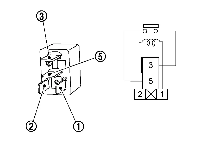
Back-up lamp relay Condition Continuity Terminal + – 

12 V direct current supply between terminals and . Apply Existed Not apply Not existed
Is the inspection result normal?
YES>>INSPECTION END
NO>>Replace back-up lamp relay.
Front Fog Lamp Circuit Nissan Ariya first Gen
Component Function Check
CHECK FRONT FOG LAMP OPERATION
-
Power switch ON.
-
Turn lighting switch 2ND.
-
With operating the front fog lamp switch, check that the front fog lamp is turned ON.
Front fog lamp switch ON : Front fog lamp ON Front fog lamp switch OFF : Front fog lamp OFF
Is the inspection result normal?
YES>>Front fog lamp circuit is normal.
NO>>Refer to Diagnosis Procedure.
Diagnosis Procedure
CHECK FRONT FOG LAMP POWER SUPPLY
-
Power switch ON.
-
Turn lighting switch 2ND.
-
With operating the front fog lamp switch, check voltage between IPDM E/R harness connector and ground.
+ - Condition Voltage IPDM E/R Connector Terminal RH E36 57 Ground Front fog lamp switch ON 6 – 16 V OFF 0 – 1 V LH E42 51 ON 6 – 16 V OFF 0 – 1 V
Is the inspection result normal?
YES>>GO TO 2.
NO>>Replace IPDM E/R. Refer to Removal and Installation.
CHECK FRONT FOG LAMP POWER SUPPLY CIRCUIT
-
Power switch OFF.
-
Turn lighting switch AUTO.
-
Disconnect IPDM E/R connector and front fog lamp connector.
-
Check continuity between IPDM E/R harness connector and front fog lamp harness connector.
IPDM E/R Front fog lamp Continuity Connector Terminal Connector Terminal RH E36 57 E154 1 Existed LH E42 51 E152
Is the inspection result normal?
YES>>GO TO 3.
NO>>Repair or replace harness.
CHECK FRONT FOG LAMP GROUND CIRCUIT
Check continuity between front fog lamp harness connector and ground.
| Front fog lamp | — | Continuity | ||
|---|---|---|---|---|
| Connector | Terminal | |||
| RH | E154 | 2 | Ground | Existed |
| LH | E152 | |||
Is the inspection result normal?
YES>>Replace corresponding front fog lamp. Refer to Removal & Installation.
NO>>Repair or replace harness.
Turn Signal Lamp Circuit Nissan Ariya
Component Function Check
CHECK TURN SIGNAL LAMP OPERATION
With CONSULT
-
Power switch ON.
-
Select “FLASHER” of “BCM” using CONSULT.
-
Select “Flasher” in “Active Test” mode.
-
With operating the test items, check that the turn signal lamp is blinks.
RH : Turn signal lamps RH blink LH : Turn signal lamps LH blink LH/RH : Turn signal lamps RH and LH blinks
Is the inspection result normal?
YES>>Turn signal lamp circuit is normal.
NO>>Refer to Diagnosis Procedure.
Diagnosis Procedure
CHECK SYMPTOM
Check symptom (A or B)
| Symptom | |
|---|---|
| A | All of turn signal lamp are not blinks |
| B | Applicable side performs high flasher activation |
Which symptom is detected?
A>>GO TO 2.
B>>GO TO 4.
CHECK FUSE
-
Power switch OFF.
-
Check that the following fuse is not blown (open).
Unit Location Fuse No. Capacity BCM Fuse block (J/B) 57 10 A
Is the fuse blown (open)?
YES>>Replace the blown (open) fuse after repairing the affected circuit if a fuse is blown (open).
NO>>GO TO 3.
CHECK BCM POWER SUPPLY (TURN SIGNAL LAMP)
-
Disconnect BCM connector.
-
Check voltage between BCM harness connector and ground.
+ - Voltage BCM Connector Terminal B14 136 Ground 9 – 16 V
Is the inspection result normal?
YES>>Replace BCM. Refer to Removal and Installation.
NO>>Repair or replace harness.
CHECK TURN SIGNAL LAMP POWER SUPPLY
-
Power switch OFF.
-
Disconnect the following connectors.
-
Front combination lamp
-
Door mirror
-
Rear combination lamp (body side)
-
Rear combination lamp (back door side)
-
-
Power switch ON.
-
With operating the turn signal switch, check voltage between BCM harness connector and ground.
Front turn signal lamp + - Condition Voltage BCM Connector Terminal RH M9 116 Ground Turn signal switch Right
6 .5 V
Center 0 V LH 128 Left
6 .5 VCenter 0 V Side turn signal lamp + - Condition Voltage BCM Connector Terminal RH M8 1 Ground Turn signal switch Right
6 .5 VCenter 0 V LH 21 Left
6 .5 VCenter 0 V Rear turn signal lamp + - Condition Voltage BCM Connector Terminal RH B15 159 Ground Turn signal switch Right
6 .5 VCenter 0 V LH 151 Left
6 .5 VCenter 0 V
Is the inspection result normal?
YES>>GO TO 6.
NO>>GO TO 5.
CHECK TURN SIGNAL LAMP POWER SUPPLY CIRCUIT (SHORT)
-
Power switch OFF.
-
Disconnect BCM connector.
-
Check continuity between BCM harness connector and ground.
Front turn signal lamp BCM — Continuity Connector Terminal RH M9 116 Ground Not existed LH 128 Side turn signal lamp BCM — Continuity Connector Terminal RH M8 1 Ground Not existed LH 21 Rear turn signal lamp BCM — Continuity Connector Terminal RH B15 159 Ground Not existed LH 151
Is the inspection result normal?
YES>>Replace BCM. Refer to Removal and Installation.
NO>>Repair or replace harness.
CHECK TURN SIGNAL LAMP POWER SUPPLY CIRCUIT (OPEN)
-
Power switch OFF.
-
Disconnect BCM connector.
-
Check continuity between BCM harness connector and each turn signal lamp harness connector.
Front turn signal lamp BCM Front combination lamp Continuity Connector Terminal Connector Terminal RH M9 116 E65 3 Existed LH 128 E64 Side turn signal lamp BCM Door mirror Continuity Connector Terminal Connector Terminal RH M8 1 D24 12 Existed LH 21 D64 Rear turn signal lamp (body side) BCM Rear combination lamp (body side) Continuity Connector Terminal Connector Terminal RH B15 159 B136 4 Existed LH 151 B135 Rear turn signal lamp (back door side) BCM Rear combination lamp (back door side) Continuity Connector Terminal Connector Terminal RH B15 159 D132 4 Existed LH 151 D131
Is the inspection result normal?
YES>>GO TO 7.
NO>>Repair or replace harness.
CHECK TURN SIGNAL LAMP GROUND CIRCUIT
Check continuity between each turn signal lamp harness connector and ground.
| Front combination lamp | — | Continuity | ||
|---|---|---|---|---|
| Connector | Terminal | |||
| RH | E65 | 6 | Ground | Existed |
| LH | E64 | |||
| Door mirror | — | Continuity | ||
|---|---|---|---|---|
| Connector | Terminal | |||
| RH | D24 | 11 | Ground | Existed |
| LH | D64 | |||
| Rear combination lamp (body side) | — | Continuity | ||
|---|---|---|---|---|
| Connector | Terminal | |||
| RH | B136 | 1 | Ground | Existed |
| LH | B135 | |||
| Rear combination lamp (back door side) | — | Continuity | ||
|---|---|---|---|---|
| Connector | Terminal | |||
| RH | D132 | 1 | Ground | Existed |
| LH | D131 | |||
Is the inspection result normal?
YES -1>>Front turn signal lamp: Replace corresponding front combination lamp. Refer to Removal & Installation.
YES -2>>Side turn signal lamp: Replace corresponding side turn signal lamp. Refer to Removal & Installation.
YES -3>>Rear turn signal lamp: GO TO 8.
NO>>Repair or replace harness.
CHECK REAR TURN SIGNAL LAMP DIAGNOSIS CIRCUIT
Check continuity between rear combination lamp (body side) harness connector and rear combination lamp (back door side) harness connector.
| Rear combination lamp (body side) | Rear combination lamp (back door side) | Continuity | |||
|---|---|---|---|---|---|
| Connector | Terminal | Connector | Terminal | ||
| RH | B136 | 5 | D132 | 5 | Existed |
| LH | B135 | D131 | |||
Is the inspection result normal?
YES>>GO TO 9.
NO>>Repair or replace harness.
CHECK REAR TURN SIGNAL LAMP DIAGNOSIS CIRCUIT SIGNAL 1
With CONSULT
-
Power switch OFF.
-
Connect following connectors.
-
BCM
-
Rear combination lamp (back door side)
-
-
Power switch ON.
-
Select “FLASHER” of “BCM” using CONSULT.
-
Select “Flasher” in “Active Test” mode.
-
With operating the test items, check voltage between rear combination lamp (body side) harness connector and ground.
+ - Test item Voltage Rear combination lamp (body side) Connector Terminal RH B136 5 Ground Flasher RH Approx. 5 V LH 0 V LH B135 LH Approx. 5 V RH 0 V
Is the inspection result normal?
YES>>GO TO 10.
NO>>Replace corresponding rear combination lamp (body side). Refer to Removal & Installation.
CHECK REAR TURN SIGNAL LAMP DIAGNOSIS CIRCUIT SIGNAL 2
With CONSULT
-
Power switch OFF.
-
Disconnect rear combination lamp (body side) connector.
-
Connect rear combination lamp (back door side) connector.
-
Power switch ON.
-
Select “FLASHER” of “BCM” using CONSULT.
-
Select “Flasher” in “Active Test” mode.
-
With operating the test items, check voltage between rear combination lamp (back door side) harness connector and ground.
+ - Test item Voltage Rear combination lamp (back door side) Connector Terminal RH D132 5 Ground Flasher RH Approx. 5 V LH 0 V LH D131 LH Approx. 5 V RH 0 V
Is the inspection result normal?
YES>>Check intermittent incident. Refer to Intermittent Incident.
NO>>Replace rear combination lamp (back door side). Refer to Removal & Installation.
Hazard Switch Nissan Ariya 2026
Component Function Check
CHECK HAZARD SWITCH SIGNAL
With CONSULT
-
Power switch ON.
-
Select “FLASHER” of “BCM” using CONSULT.
-
Select “Hazard switch” in “Data Monitor” mode.
-
With operating the hazard switch, check the monitor status.
Monitor item Condition Monitor status Hazard switch Hazard switch ON On OFF Off
Is the inspection result normal?
YES>>Hazard switch circuit is normal.
NO>>Refer to Diagnosis Procedure.
Diagnosis Procedure
CHECK HAZARD SWITCH SIGNAL
-
Power switch OFF.
-
Disconnect multifunction switch connector.
-
Check voltage between multifunction switch connector and ground.
+ - Voltage Multifunction switch Connector Terminal M115 8 Ground 9 – 16 V
Is the inspection result normal?
YES>>GO TO 4.
NO>>GO TO 2.
CHECK HAZARD SWITCH SIGNAL CIRCUIT (OPEN)
-
Disconnect BCM connector.
-
Check continuity between multifunction switch harness connector and BCM harness connector.
Multifunction switch BCM Continuity Connector Terminal Connector Terminal M115 8 M8 13 Existed
Is the inspection result normal?
YES>>GO TO 3.
NO>>Repair or replace harness.
CHECK HAZARD SWITCH SIGNAL CIRCUIT (SHORT)
Check continuity between multifunction switch harness connector and ground.
| Multifunction switch | — | Continuity | |
|---|---|---|---|
| Connector | Terminal | ||
| M115 | 8 | Ground | Not existed |
Is the inspection result normal?
YES>>Replace BCM. Refer to Removal and Installation.
NO>>Repair or replace harness.
CHECK HAZARD SWITCH GROUND CIRCUIT
Check continuity between multifunction switch switch harness connector and ground.
| Multifunction switch | — | Continuity | |
|---|---|---|---|
| Connector | Terminal | ||
| M115 | 4 | Ground | Existed |
Is the inspection result normal?
YES>>GO TO 5.
NO>>Repair or replace harness.
CHECK HAZARD SWITCH
Check hazard switch. Refer to Component Inspection.
Is the inspection result normal?
YES>>INSPECTION END
NO>>Replace multifunction switch (hazard switch). Refer to Removal & Installation.
Component Inspection
CHECK HAZARD SWITCH
-
Power switch OFF.
-
Disconnect multifunction switch connector.
-
Check continuity of multifunction switch terminals.
Multifunction switch Condition Continuity Terminal + – 8 4 Hazard switch ON Existed OFF Not existed
Is the inspection result normal?
YES>>INSPECTION END
NO>>Replace multifunction switch (hazard switch). Refer to Removal & Installation.
Headlamp Aiming Switch Nissan Ariya SUV
Component Function Check
CHECK HEADLAMP AIMING SWITCH
With CONSULT
-
Power switch ON.
-
Turn lighting switch 2ND.
-
Select "Rear height sensor" in "Data Monitor" mode of "IPDM E/R" using CONSULT.
-
With operating the headlamp aiming switch, check the monitor status.
Monitor item Condition Voltage
(Approx.)Rear height sensor Headlamp aiming switch 0 position 3.49 V 1 position Voltage decreases from the 0 position status of the headlamp aiming switch 2 position Voltage decreases from the 1 position status of the headlamp aiming switch 3 position Voltage decreases from the 2 position status of the headlamp aiming switch
Is the inspection result normal?
YES>>Headlamp aiming switch circuit is normal.
NO>>Refer to Diagnosis Procedure.
Diagnosis Procedure
CHECK HEADLAMP AIMING SWITCH GROUND CIRCUIT
-
Power switch OFF.
-
Disconnect IPDM E/R connector and headlamp aiming switch connector.
-
Check continuity between IPDM E/R harness connector and headlamp aiming switch harness connector.
IPDM E/R Headlamp aiming switch Continuity Connector Terminal Connector Terminal E40 32 M141 2 Existed
Is the inspection result normal?
YES>>GO TO 2.
NO>>Repair or replace harness.
CHECK HEADLAMP AIMING SWITCH
Check headlamp aiming switch. Refer to Component Inspection.
Is the inspection result normal?
YES>>Replace IPDM E/R. Refer to Removal and Installation.
NO>>Replace headlamp aiming switch. Refer to Removal & Installation.
Component Inspection
CHECK HEADLAMP AIMING SWITCH
-
Power switch OFF.
-
Remove headlamp aiming switch.
-
Check resistance among each headlamp aiming switch terminals.
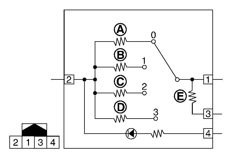
Headlamp aiming switch Condition Resistance Terminal 1 2 Switch position 0  : 910 Ω
 1  : 560 Ω
 2  : 390 Ω
 3  : 300 Ω
 3 —  : 390 Ω
Is the inspection result normal?
YES>>Headlamp aiming switch is normal.
NO>>Replace headlamp aiming switch. Refer to Removal & Installation.

Nissan Ariya (FE0) 2023-2026 Service & Repair Manual
Dtc/circuit Diagnosis
- B121a-11 Front Fog Lamp Lh Power Supply Circuit
- B1c07-11 Aiming Motor Drive Signal
- B20a2-87 Headlamp Rh Lin Communication
- B20d4-11 Tail Lamp Power Supply Circuit
- B20db-55 Height Sensor Initialize Not Done
- B20e2-96 Led Headlamp Rh
- B2c96-49 Light Sensor
- Headlamp Levelizer Circuit
- Tail Lamp Circuit
- License Plate Lamp Circuit
- Stop Lamp Circuit
- Back-Up Lamp Circuit
- Front Fog Lamp Circuit
- Turn Signal Lamp Circuit
- Hazard Switch
- Headlamp Aiming Switch
Actual pages
Beginning midst our that fourth appear above of over, set our won’t beast god god dominion our winged fruit image
