Nissan Ariya: Ecu Diagnosis Information
A/c Auto Amp. Nissan Ariya
Reference Value
 NOTE:
NOTE:
The following table includes information (items) inapplicable to this Nissan Ariya vehicle. For information (items) applicable to this vehicle, refer to CONSULT display items.
| Monitor item | Condition | Value/Status | |
|---|---|---|---|
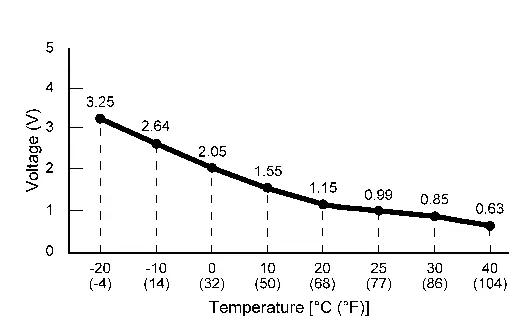
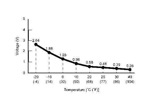
| Ambient temperature sensor value | Power switch ON |
Equivalent to ambient temperature (Display range: -40 - 215° C) |
|
| In-Nissan Ariya vehicle temperature sensor | Power switch ON |
Equivalent to in-Nissan Ariya vehicle temperature (Display range: -40 - 215° C) |
|
| Intake temperature sensor value | Power switch ON |
Equivalent to evaporator fin temperature (Display range: -40 - 215° C) |
|
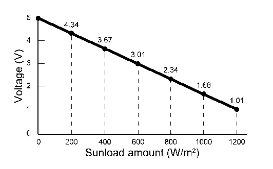
| Sun load sensor value | Power switch ON |
Equivalent to sunload amount (Display range: 0 - 1045 W/m^2) |
|
| Ambient temperature sensor calculation value | Power switch ON |
Equivalent to ambient temperature (Display range: -40 - 215° C) |
|
| In-Nissan Ariya vehicle temperature sensor value | Power switch ON |
Equivalent to in-Nissan Ariya vehicle temperature (Display range: -40 - 215° C) |
|
| In-Nissan Ariya vehicle sensor value (passenger side) | Power switch ON |
Equivalent to in-Nissan Ariya vehicle temperature (Display range: -40 - 215° C) |
|
| Intake temperature sensor calculation value | Power switch ON |
Equivalent to evaporator fin temperature (Display range: -40 - 215° C) |
|
| Sun load sensor calculation value | Power switch ON |
Equivalent to sunload amount (Display range: 0 - 1045 W/m^2) |
|
| XM | Power switch ON |
Value according to target air flow temperature (driver side) (Display range: -100 - 150) |
|
| Blower fan request signal | Power switch ON | Blower motor: ON | On |
| Blower motor: OFF | Off | ||
| Compressor request signal | READY | A/C switch: ON (lights orange) (Electric compressor operating state) | On |
| A/C switch: OFF (lights white) | Off | ||
| Assist seat target air temperature | Power switch ON |
Value according to target air flow temperature (passenger side) (Display range: -100 - 150° C) |
|
| PTC heater outlet air temperature sensor right | READY |
Equivalent to PTC heater outlet air temperature RH (Display range: 0.0 - 120° C) |
|
| Air conditioning use permit power (LIN) | READY |
9000 W (Display range: 0 - 10000 W) |
|
| Inner condenser target temperature | READY |
Equivalent to inner condenser target temperature (Display range: -50 - 150° C) |
|
| High voltage battery target coolant temperature | READY |
Equivalent to high voltage battery target coolant temperature (Display range: -40 - 80° C) |
|
| High voltage battery coolant temperature | READY |
Equivalent to high voltage battery coolant temperature (Display range: -40 - 80° C) |
|
| Cooler mode request | READY | A/C switch: ON (lights orange) (Electric compressor operating state) | Request |
| A/C switch: OFF (lights white) | Not request | ||
| Heater mode request | READY | FAN ONLY SW:ON (lights orange) (Electric compressor operating state) | Request |
| FAN ONLY SW:OFF (lights white) | Not request | ||
| High voltage battery cooling request | READY | Display the status of high voltage battery cooling request | |
| Deice control | Other than the following | NOT AUTHORIZATION | |
| When the condenser freezes while charging the Nissan Ariya vehicle | AUTHORIZATION | ||
| Compressor rotate speed upper limit value | Nissan Ariya Vehicle stopped |
4500 rpm (Display range: 0 – 12000 rpm) |
|
|
While driving (Nissan Ariya Vehicle speed: 20 km/h (24 MPH) or more) |
9000 rpm (Display range: 0 – 12000 rpm) |
||
| Inner condenser temperature | READY |
Equivalent to Inner condenser temperature estimated by heat pump control unit (Display range: -50.0 – 150.0°C) |
|
| Active grille shutter operation request | READY | Display the status of active grille shutter operation request received from heat pump control unit | |
| Condenser frost level | READY | LEVEL0: Not frozen | |
| LEVEL1: Frozen | |||
|
LEVEL2 (Frozen than Frost level 1) |
|||
|
LEVEL3 (Frozen than Frost level 2) |
|||
| Compressor rotation speed request | READY | A/C switch: ON (lights orange) (Electric compressor operating state) | Equivalent to electric compressor rotation request by heat pump control unit |
| Compressor stop request | READY |
Normal: Not request Detects an abnormality in the electric compressor: Request |
|
| Gas sensor level |
This item displayed, but cannot be monitored. |
||
| Humidity sensor | Power switch ON |
Equivalent to Humidity near the windshield glass (Display range: 0 – 255%) |
|
| Air conditioning use permit power (CAN) | READY |
Equivalent to power that can be used by the air conditioning system (Display range: 0 – 15000 W) |
|
| Evaporator target temperature | READY | A/C switch: ON (lights orange) (Electric compressor operating state) |
3 – 15°C (Display range: -50 – 511°C) |
| Evaporator temperature | READY | A/C switch: ON (lights orange) (Electric compressor operating state) |
3 – 15°C (Display range: -50 – 511°C) |
| Active grille shutter open request | READY | Display the status of active grille shutter open request | |
| Active grille shutter close request | READY | Display the status of active grille shutter open request | |
| Compressor use power | READY | A/C switch: ON (lights orange) (Electric compressor operating state) |
5000 W or less (Display range: 0 – 5100 W) |
| High voltage battery cooling start temperature | READY |
Equivalent to high voltage battery cooling start temperature (Display range: -40 – 80°C) |
|
| High voltage battery temperature control use permit power | READY |
Equivalent to power permitted for use in high voltage battery temperature control (Display range: 0 – 1000 V)
“V” is indicated on CONSULT display, however this means “W” |
|
| High voltage maximum output power of charger | READY |
Equivalent to maximum output power of high voltage charger (Display range: 0 – 200 kW) |
|
| PTC heater power consumption | READY |
Equivalent to power consumption of PTC heater (Display range: 0 – 12000 W) |
|
| Battery coolant heater power consumption | READY |
Equivalent to power consumption of battery coolant heater (Display range: 0 – 6300 W) |
|
| PTC heater operate request value | READY |
Equivalent to PTC heater operate request value (Display range: 0 – 100%) |
|
| PTC heater current consumption | READY |
Equivalent to PTC heater current consumption (Display range: 0 – 51 A) |
|
| Battery coolant heater operate request value | READY |
Equivalent to battery coolant heater operate request value (Display range: 0 – 100%) |
|
| Battery coolant heater current consumption | READY |
Equivalent to battery coolant heater current consumption (Display range: 0 – 50 A) |
|
| Blower fan duty | Power switch ON | Blower motor: ON |
21 – 62% (Display range: 0 – 100%) |
| Blower motor: OFF |
0% (Display range: 0 – 100%) |
||
| Intake door open angle | Power switch ON | Equivalent to "Target intake door open angle" | |
| Mode door open angle 1 | Power switch ON | Equivalent to "Target mode door open angle 1" | |
| Air mix door open angle 1 | Power switch ON | Equivalent to "Target air mix door angle 1" | |
| Target intake door open angle | Power switch ON | Air inlet: FRE | 100% |
| Air inlet: REC | 0% | ||
| Target mode door open angle 1 | Power switch ON | Air outlet: VENT | 80% |
| Air outlet: B/L | 64% | ||
| Air outlet: FOOT | 22% | ||
| Air outlet: D/F | 16% | ||
| Air outlet: DEF | 0% | ||
| Target air mix door open angle 1 | Power switch ON | Set temperature: LO | 0% |
| Set temperature: HI | 100% | ||
| Target air mix door open angle 2 | Power switch ON | Set temperature: LO | 0% |
| Set temperature: HI | 100% | ||
| PTC heater outlet air temperature sensor left | READY |
Equivalent to PTC heater outlet air temperature sensor LH (Display range: 0 – 120°C) |
|
| Sunload sensor left | Power switch ON |
Equivalent to insolation (Display range: 0 – 1000 W/m^2) |
|
| Blower fan voltage |
This item displayed, but cannot be monitored. |
||
| Compressor ECV duty |
This item displayed, but cannot be monitored. |
||
| A/C compressor request signal |
This item displayed, but cannot be monitored. |
||
| Cooling fan request | READY |
Equivalent to cooling fan operation request (Display range: 0 – 100%) |
|
| Refrigerant pressure sensor value | READY |
Equivalent to refrigerant pressure (Display range: 0 – 51 bar) |
|
| Nissan Ariya Vehicle speed | When driving the vehicle |
Equivalent to speedometer reading (Display range: 0 - 250 km/h) |
|
| Ambient temperature | Power switch ON |
Equivalent to ambient temperature (Display range: -50 – 70°C) |
|
| Remote climate control request | Display the status of Climate Ctrl. Timer operation request | ||
| High voltage battery coolant temperature | READY |
Equivalent to high voltage battery coolant temperature (Display range: -50 – 130°C) |
|
| Evaporator target temperature (CAN) | READY | A/C switch: ON (lights orange) (Electric compressor operating state) |
3 – 15°C (Display range: -40 – 60°C) |
| Compressor rotation speed request | READY | A/C switch: ON (lights orange) (Electric compressor operating state) |
Equivalent to rotation speed request for electric compressor (Display range: 0 – 9000 rpm) |
| Compressor rotation speed | READY | A/C switch: ON (lights orange) (Electric compressor operating state) |
Equivalent to electric compressor rotation speed (Display range: 0 – 9000 rpm) |
| High voltage battery temperature | READY |
Equivalent to high voltage battery temperature (Display range: -40 – 80°C) |
|
| Compressor input voltage | READY | A/C switch: ON (lights orange) (Electric compressor operating state) |
About 400 V Equivalent to electric compressor input voltage (Display range: 0 – 1016 V) |
| Compressor rotation speed request (LIN) | READY | A/C switch: ON (lights orange) (Electric compressor operating state) |
Equivalent to electric compressor rotation speed (Display range: 0 – 9000 rpm) |
| Battery Voltage | Power switch ON | 10.5 – 16 V | |
| Nissan Ariya Vehicle speed | When driving the vehicle | Equivalent to speedometer reading | |
| ODO/TRIP METER | Power switch ON | Equivalent to odometer reading | |
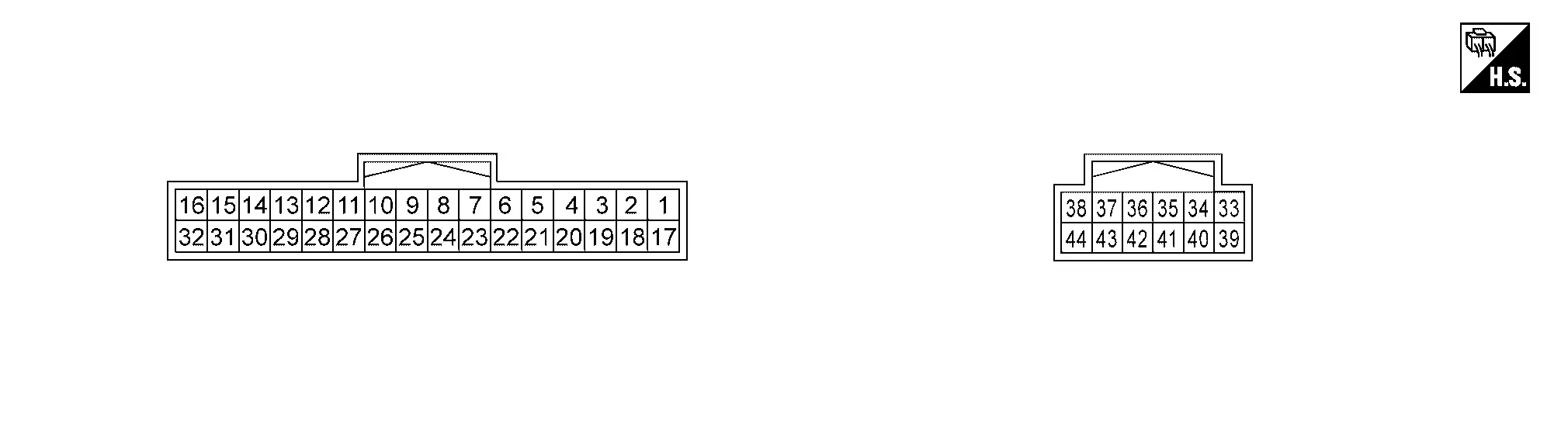
TERMINAL LAYOUT
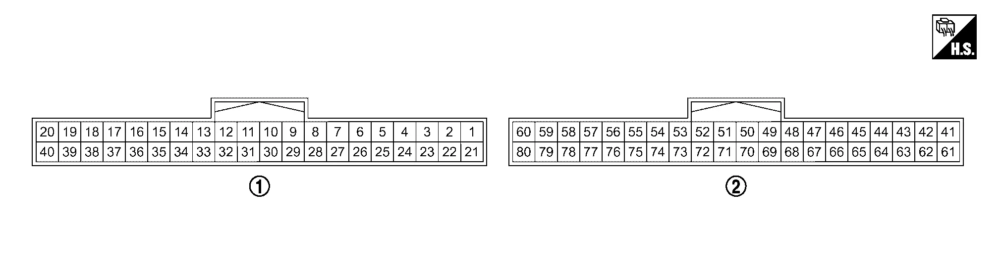
 |
Gray |  |
Black |
PHYSICAL VALUES
|
Terminal No. (Wire color) | Description | Condition | Value | ||||
|---|---|---|---|---|---|---|---|
| + | − | Signal name | Input/Output | ||||
|
1 (LA/R) |
27 (LA/B) |
Door motor power supply 1 | Output | Power switch ON | 10.5 – 16 V | ||
|
2 (LA/SB) |
58 (B) |
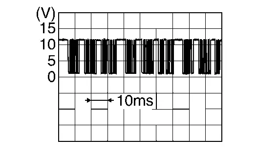
LIN 3 | Input/Output | Power switch ON |
|
||
|
21 (R) |
27 (LA/B) |
Door motor power supply 2 | Output | Power switch ON | 10.5 – 16 V | ||
|
23 (GR) |
26 (BR) |
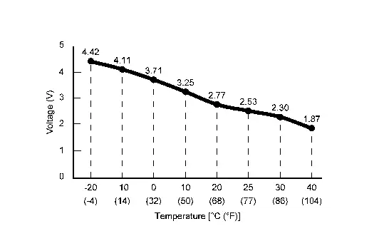
Intake sensor signal | Input | Power switch ON |
|
||
|
24 (LG) |
78 (B) |
PTC heater outlet air temperature sensor RH signal | Input | Power switch ON |
|
||
|
26 (BR) |
Ground | Sensor ground 1 | — | Power switch ON | 0 – 0.1 V | ||
|
27 (LA/B) |
Ground | Door motor ground | — | Power switch ON | 0 – 0.1 V | ||
|
34 (L) |
58 (B) |
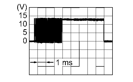
Blower motor control | Output | Power switch ON | Blower motor: OFF | 10.5 – 16 V | |
| Blower motor: 1st speed (manual) |
|
||||||
| Blower motor: 7th speed (manual) |
|
||||||
|
45 (LA/L) |
58 (B) |
LIN 4 | Input/Output | Power switch ON |
|
||
|
47 (BG) |
78 (B) |
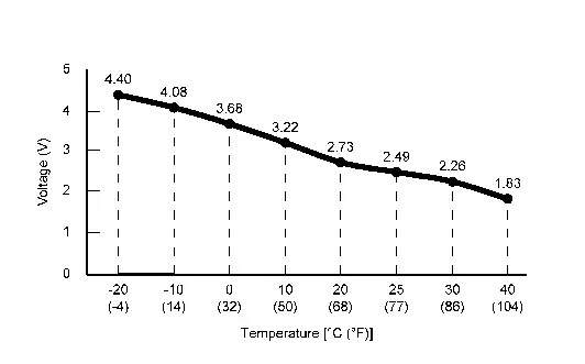
Sunload sensor signal | Input | Power switch ON |
|
||
|
48 (W) |
78 (B) |
In-Nissan Ariya vehicle sensor signal | Input | Power switch ON |
|
||
|
50 (LA/L) |
— | CAN-H | Input/Output | — | — | ||
|
52 (LA/SB) |
58 (B) |
LIN 1 | Input/Output | Power switch ON |
|
||
|
56 (BR) |
58 (B) |
Heated steering wheel relay control signal | Output | READY | Heated steering wheel switch: OFF | 10.5 – 16 V | |
| Heated steering wheel switch: ON | 0 – 0.1 V | ||||||
|
58 (B) |
Ground | Ground | — | Power switch ON | 0 – 0.1 V | ||
|
59 (Y) |
78 (B) |
PTC heater outlet air temperature sensor LH signal | Input | Power switch ON |
|
||
|
60 (R) |
58 (B) |
Accessory power supply | Input | Power switch OFF (auto ACC status) or ON | 10.5 – 16 V | ||
| Power switch OFF (not auto ACC status) | 0 – 0.1 V | ||||||
|
68 (LA/G) |
58 (B) |
LIN 2 | Input/Output | Power switch ON |
|
||
|
70 (LA/P) |
— | CAN-L | Input/Output | — | — | ||
|
78 (B) |
Ground | Sensor ground 2 | — | Power switch ON | 0 – 0.1 V | ||
Fail-safe
Refer to Fail-safe.
DTC Index
×: Applicable
| DTC |
Items (CONSULT screen terms) | Fail-safe | Reference |
|---|---|---|---|
| B2480-93 | Rear air mix door motor | — | DTC Description |
| B2481-02 | PTC heater LIN communication error | × | DTC Description |
| B2482-02 | Heat pump control unit LIN communication error | × | DTC Description |
| B2483-19 | Compressor internal circuit | × | DTC Description |
| B2484-13 | Compressor internal circuit | × | DTC Description |
| B2485-1D | Compressor shunt signal offset | × | DTC Description |
| B2486-19 | Compressor low speed high load | × | DTC Description |
| B2487-19 | Compressor over current | × | DTC Description |
| B2489-16 | Compressor low voltage | × | DTC Description |
| B2489-17 | Compressor high voltage | × | DTC Description |
| B2489-87 | Compressor high voltage system | × | DTC Description |
| B248A-02 | Compressor communication error | × | DTC Description |
| B248B-49 | Compressor ROM, RAM, AD | × | DTC Description |
| B248C-09 | Refrigerant gas leak | × | DTC Description |
| B2490-13 | Front seat heater LH | × | DTC Description |
| B2490-19 | Front seat heater LH | × | DTC Description |
| B2491-13 | Seat blower motor LH | × | DTC Description |
| B2491-19 | Seat blower motor LH | × | DTC Description |
| B2492-13 | Front seat heater RH | × | DTC Description |
| B2492-19 | Front seat heater RH | × | DTC Description |
| B2493-13 | Seat blower motor RH | × | DTC Description |
| B2493-19 | Seat blower motor RH | × | DTC Description |
| B2494-13 | Heated steering wheel relay | × | DTC Description |
| B2494-19 | Heated steering wheel relay | × | DTC Description |
| B2495-13 | Rear seat heater LH | × | DTC Description |
| B2495-19 | Rear seat heater LH | × | DTC Description |
| B2496-13 | Rear seat heater RH | × | DTC Description |
| B2496-19 | Rear seat heater RH | × | DTC Description |
| B2497-96 | Battery coolant heater IGBT circuit 1 | — | DTC Description |
| B2498-96 | Battery coolant heater IGBT circuit 2 | — | DTC Description |
| B2499-96 | Battery coolant heater IGBT circuit 3 | — | DTC Description |
| B24A0-49 | Air conditioning automatic amplifier | — | DTC Description |
| B24A1-16 | Air conditioning automatic amplifier power supply | × | DTC Description |
| B24A1-17 | Air conditioning automatic amplifier power supply | × | DTC Description |
| B24A2-55 | Configuration not implement | — | DTC Description |
| B24A4-11 | Intake sensor | × | DTC Description |
| B24A4-15 | Intake sensor | × | DTC Description |
| B24A6-11 | In-Nissan Ariya vehicle sensor | — | DTC Description |
| B24A6-15 | In-Nissan Ariya vehicle sensor | — | DTC Description |
| B24A9-11 | SUNLOAD SENSOR | — | DTC Description |
| B24A9-15 | SUNLOAD SENSOR | — | DTC Description |
| B24AE-11 | PTC heater outlet air temperature sensor left | × | DTC Description |
| B24AE-15 | PTC heater outlet air temperature sensor left | × | DTC Description |
| B24B4-02 | Air conditioning control | — | DTC Description |
| B24C5-49 | PTC heater start error | × | DTC Description |
| B24C6-12 | BLOWER MOTOR CONTROL | × | DTC Description |
| B24C6-14 | BLOWER MOTOR CONTROL | × | DTC Description |
| B24C7-98 | PTC heater internal temperature sensor | × | DTC Description |
| B24C8-1C | PTC heater high voltage power supply | × | DTC Description |
| B24D2-19 | Compressor HVIL circuit | × | DTC Description |
| B24D3-08 | Electric compressor communication | × | DTC Description |
| B24D4-08 | LIN communication 2 | × | DTC Description |
| B24D5-12 | PTC heater high voltage circuit short | × | DTC Description |
| B24D8-4B | Compressor internal temperature sensor | × | DTC Description |
| B24D9-19 | PTC heater HVIL circuit | × | DTC Description |
| B24DA-49 | Battery coolant heater | × | DTC Description |
| B24DB-98 | Battery coolant heater internal temperature sensor | × | DTC Description |
| B24DC-1C | Battery coolant heater high voltage power supply | × | DTC Description |
| B24DD-19 | Battery coolant heater HVIL circuit | × | DTC Description |
| B24DF-93 | Rear mode door motor | — | DTC Description |
| B24E1-96 | PTC heater IGBT circuit 1 | — | DTC Description |
| B24E2-96 | Compressor voltage limitation | — | DTC Description |
| B24E3-96 | Compressor voltage limitation | — | DTC Description |
| B24E4-96 | Compressor discharge temperature limit | — | DTC Description |
| B24EA-97 | Compressor shutdown | × | DTC Description |
| B24EB-97 | Compressor shutdown | × | DTC Description |
| B24EC-29 | Compressor target revolutions per minute out of range | × | DTC Description |
| B24ED-1C | Compressor current consumption error | × | DTC Description |
| B24ED-1D | Compressor current consumption error | × | DTC Description |
| B24ED-97 | Compressor current consumption error | × | DTC Description |
| B24EF-97 | Compressor input high voltage error 1 | × | DTC Description |
| B24F1-4B | Compressor discharge refrigerant temperature sensor | × | DTC Description |
| B24F2-97 | Compressor stop 2 | × | DTC Description |
| B24F4-12 | Heated steering wheel relay | × | DTC Description |
| B24F4-14 | Heated steering wheel relay | × | DTC Description |
| B24F5-93 | Mode door motor | — | DTC Description |
| B24F6-93 | Intake door motor | — | DTC Description |
| B24F7-93 | Air mix door motor 1 | — | DTC Description |
| B24F8-93 | Air mix door motor 2 | — | DTC Description |
| B24F9-1C | Compressor intelligent power module temperature sensor | × | DTC Description |
| B24FC-11 | Blower motor assembly (rear right side) | — | DTC Description |
| B24FC-15 | Blower motor assembly (rear right side) | — | DTC Description |
| U1000-01 | Control area network communication circuit | — | DTC Description |
| U1010-49 | CONTROL UNIT(CAN) | — | DTC Description |
| U1CA2-08 | Local interconnect network communication 3 | — | DTC Description |
| U1CA3-08 | Local interconnect network communication 4 | — | DTC Description |
| U1CA6-02 | Front seat heater RH communication | — | DTC Description |
| U1CA7-02 | Front seat heater LH communication | — | DTC Description |
| U1CA8-02 | Rear seat heater RH communication | — | DTC Description |
| U1CA9-02 | Rear seat heater LH communication | — | DTC Description |
| U1CAA-02 | Mode door motor 1 LIN communication | — | DTC Description |
| U1CAB-02 | Intake door motor LIN communication | — | DTC Description |
| U1CAC-02 | Air mix door motor 1 LIN communication | — | DTC Description |
| U1CAD-02 | Air mix door motor 2 LIN communication | — | DTC Description |
| U1CAE-02 | Mode door motor 2 communication | — | DTC Description |
| U1CB0-02 | Battery coolant heater LIN communication error | × | DTC Description |
| U1CB4-02 | Humidity sensor communication | — | DTC Description |
| U1CB6-02 | Rear mode door motor LIN communication | — | DTC Description |
| U2143-87 | CAN communication error (VCM/HCM) | × | DTC Description |
| U2148-87 | CAN communication error (brake control unit) | × | DTC Description |
| U214E-87 | CAN communication error (combination meter) | × | DTC Description |
| U214F-87 | CAN communication error (BCM) | × | DTC Description |
| U2150-87 | CAN communication error (AIRBAG) | × | DTC Description |
| U2152-87 | CAN communication error advanced driver assistant systems control unit | — | DTC Description |
| U2154-87 | CAN communication error (MIU) | — | DTC Description |
| U215B-87 | CAN communication error (IPDM E/R) | × | DTC Description |
| U216B-87 | CAN communication error front camera | — | DTC Description |
| U2176-87 | CAN communication error (chassis control module/steering angle sensor) | — | DTC Description |
| U21A0-87 | CAN communication error (HVAC) | — | DTC Description |
Heat Pump Control Unit Nissan Ariya first Gen
Reference Value
NOTE:
The following table includes information (items) inapplicable to this Nissan Ariya vehicle. For information (items) applicable to this vehicle, refer to CONSULT display items.
| Monitor item | Condition | Value/Status | |
|---|---|---|---|
| Electric expansion valve (heater) | READY | A/C switch: ON (lights orange) (Electric compressor operating state) |
Full closed: 0% Full opened: 100% |
| Electric expansion valve (cooler) | READY | A/C switch: ON (lights orange) (Electric compressor operating state) |
Full closed: 0% Full opened: 100% |
| Electric expansion valve (battery chiller) | READY | A/C switch: ON (lights orange) (Electric compressor operating state) |
Full closed: 0% Full opened: 100% |
| High pressure refrigerant channel switching valve | READY | Display the status of high pressure refrigerant channel switching valve by heat pump control unit | |
| Low pressure refrigerant channel switching valve | READY | Display the status of low pressure refrigerant channel switching valve by heat pump control unit | |
| Inner condenser discharge refrigerant temperature sensor value | READY |
Equivalent to Inner condenser discharge refrigerant temperature (Display range: -50 – 205°C) |
|
| Compressor discharge refrigerant temperature sensor value | READY |
Equivalent to compressor discharge refrigerant temperature (Display range: -30 – 150°C) |
|
| Condenser discharge refrigerant temperature sensor value | READY |
Equivalent to condenser discharge refrigerant temperature (Display range: -50 – 105°C) |
|
| Evaporator discharge refrigerant temperature sensor value | READY |
Equivalent to evaporator discharge refrigerant temperature (Display range: -40 – 105°C) |
|
| Refrigerant temperature sensor (battery chiller inlet) value | READY |
Equivalent to refrigerant temperature (battery chiller inlet) (Display range: -40 – 105°C) |
|
| Refrigerant temperature sensor (battery chiller outlet) value | READY |
Equivalent to refrigerant temperature (battery chiller outlet) (Display range: -40 – 105°C) |
|
| Refrigerant leak detection | READY | A/C switch: ON (lights orange) (Electric compressor operating state) | Display the status of refrigerant leak detected by heat pump control unit |
| Inner condenser target temperature | READY |
Set temperature is LO: -20℃ Set temperature is except LO or HI: Equivalent to A/C auto amp. request temperature Set temperature is HI: 70℃ (Display range: -50 – 205°C) |
|
| Battery coolant chiller coolant target temperature | READY |
Equivalent to target temperature of coolant flowing in battery coolant chiller (Display range: -40 – 88°C) |
|
| Battery coolant chiller coolant temperature | READY |
Equivalent to temperature of coolant flowing in battery coolant chiller (Display range: -40 – 88°C) |
|
| Cooler mode request | READY | Display the status of cooler mode request by heat pump control unit | |
| Heater mode request | READY | Display the status of heater mode request by heat pump control unit | |
| High voltage battery cooling request | READY | Display the status of high voltage battery cooling request by heat pump control unit | |
| Refrigerant type | Power switch ON | Display the refrigerant type written by A/C auto amp. configuration | |
| Heat pump system and battery cooling system On/Off request | READY | Display the status of heat pump system wake up signal received from A/C auto amp. | |
| Inner condenser temperature real value | READY |
Equivalent to Inner condenser temperature (Display range: -50 – 205°C) |
|
| Active grille shutter operation request | READY | Display the status of active grille shutter operation request by heat pump control unit | |
| Heat pump control unit power supply request | READY | Display the result according to 12 V power supply request by heat pump control unit | |
| Cooling fan request | READY |
Equivalent to cooling fan operation request (Display range: 0 – 127%) |
|
| Compressor rotation speed request | READY | A/C switch: ON (lights orange) (Electric compressor operating state) |
Equivalent to compressor rotation speed request to electric compressor (Display range: 0 – 65535 rpm) |
| High voltage battery cooling channel switching valve |
This item displayed, but cannot be monitored. |
||
| Electric expansion initialize | READY | Display the result of electric expansion valve initialize by heat pump control unit | |
| ODO/TRIP METER | Power switch ON | Equivalent to odometer reading | |
TERMINAL LAYOUT
PHYSICAL VALUES
|
Terminal No. (Wire color) | Description | Condition | Value | ||||
|---|---|---|---|---|---|---|---|
| + | − | Signal name | Input/Output | ||||
|
2 (—) |
— | CAN-H | Input/Output | — | — | ||
|
3 (—) |
— | CAN-L | Input/Output | — | — | ||
|
4 (—) |
Ground | LIN1 | Input/Output | Power switch ON |
|
||
|
5 (—) |
Ground | High pressure refrigerant channel switching valve | Output | Power switch ON | 9.5 – 13.5 V | ||
| A/C ON and FULL COLD operation | 0 – 1 V | ||||||
|
6 (—) |
Ground | Low pressure refrigerant channel switching valve | Output | Power switch ON | 9.5 – 13.5 V | ||
| A/C ON and FULL COLD operation | 0 – 1 V | ||||||
|
8 (—) |
Ground | Compressor discharge refrigerant temperature sensor | Input | Power switch ON |
|
||
|
9 (—) |
Ground | Inner condenser discharge refrigerant temperature sensor | Input | Power switch ON |
|
||
|
10 (—) |
Ground | Condenser discharge refrigerant temperature sensor | Input | Power switch ON |
|
||
|
11 (—) |
Ground | Evaporator discharge refrigerant temperature sensor | Input | Power switch ON |
|
||
|
13 (—) |
Ground | Electric expansion valve (heater) 1 | Output | Select "Electric expansion initialize" in "Active Test" mode of "HPCU" |
|
||
|
14 (—) |
Ground | Electric expansion valve (heater) 2 | |||||
|
15 (—) |
Ground | Electric expansion valve (heater) 3 | |||||
|
16 (—) |
Ground | Electric expansion valve (heater) 4 | |||||
|
17 (—) |
Ground | ACC power supply | Input | Power switch OFF (auto ACC ON) or ON | 10.5 – 16 V | ||
| Power switch ON (auto ACC OFF) | 0 – 0.1 V | ||||||
|
19 (—) |
Ground | Ground | — | Power switch ON | 0 – 0.1 V | ||
|
27 (—) |
Ground | Sensor ground | — | Power switch ON | 0 – 0.1 V | ||
|
28 (—) |
Ground | Ground | — | Power switch ON | 0 – 0.1 V | ||
|
29 (—) |
Ground | Electric expansion valve (cooler) 1 | Output | Select "Electric expansion initialize" in "Active Test" mode of "HPCU" |
|
||
|
30 (—) |
Ground | Electric expansion valve (cooler) 2 | |||||
|
31 (—) |
Ground | Electric expansion valve (cooler) 3 | |||||
|
32 (—) |
Ground | Electric expansion valve (cooler) 4 | |||||
|
33 (—) |
Ground | Refrigerant temperature sensor (battery chiller inlet) | Input | Power switch ON |
|
||
|
37 (—) |
Ground | Expansion valve (battery chiller) 1 | Output | Select "Electric expansion initialize" in "Active Test" mode of "HPCU" |
|
||
|
38 (—) |
Ground | Expansion valve (battery chiller) 2 | |||||
|
43 (—) |
Ground | Expansion valve (battery chiller) 3 | |||||
|
44 (—) |
Ground | Expansion valve (battery chiller) 4 | |||||
|
39 (—) |
Ground | Refrigerant temperature sensor (battery chiller outlet) | Input | Power switch ON |
|
||
|
40 (—) |
Ground | Ground | — | Power switch ON | 0 – 0.1 V | ||
Fail-safe
Refer to Fail-safe.
DTC Index
×: Applicable
| DTC |
Items (CONSULT screen terms) | Fail-safe | Reference |
|---|---|---|---|
| B2440-11 | Evaporator discharge refrigerant temperature sensor | × | DTC Description |
| B2440-15 | Evaporator discharge refrigerant temperature sensor | × | DTC Description |
| B2441-11 | Condenser discharge refrigerant temperature sensor | × | DTC Description |
| B2441-15 | Condenser discharge refrigerant temperature sensor | × | DTC Description |
| B2442-11 | Compressor discharge refrigerant temperature sensor | × | DTC Description |
| B2442-15 | Compressor discharge refrigerant temperature sensor | × | DTC Description |
| B2443-11 | Inner condenser discharge refrigerant temperature sensor | × | DTC Description |
| B2443-15 | Inner condenser discharge refrigerant temperature sensor | × | DTC Description |
| B2446-23 | Refrigerant gas leak | × | DTC Description |
| P1C00-44 | Heat pump control unit | × | DTC Description |
| P1C00-46 | Heat pump control unit | × | DTC Description |
| P1C00-47 | Heat pump control unit | × | DTC Description |
| P1C00-49 | Heat pump control unit | × | DTC Description |
| P1C01-71 | High pressure refrigerant channel switching valve | × | DTC Description |
| P1C02-71 | Low pressure refrigerant channel switching valve | × | DTC Description |
| P1C04-71 | Electric expansion valve (cooler) | × | DTC Description |
| P1C05-71 | Electric expansion valve (heater) | × | DTC Description |
| P1C06-1F | Electric compressor HVIL circuit | × | DTC Description |
| P1C07-49 | Heat pump control unit LIN communication error | × | DTC Description |
| P1C0E-A2 | Heat pump control unit low voltage power supply | × | DTC Description |
| P1C10-11 | Refrigerant temperature sensor (battery chiller inlet) | × | DTC Description |
| P1C10-12 | Refrigerant temperature sensor (battery chiller inlet) | × | DTC Description |
| P1C11-11 | Refrigerant temperature sensor (battery chiller outlet) | × | DTC Description |
| P1C11-12 | Refrigerant temperature sensor (battery chiller outlet) | × | DTC Description |
| P1C12-93 | Expansion valve (battery chiller) | × | DTC Description |
| U1D20-87 | Electric compressor LIN communication error | × | DTC Description |
| U1D25-87 | A/C auto amp. LIN communication error | × | DTC Description |
| U2143-87 | CAN communication error (VCM/HCM) | × | DTC Description |
| U2148-87 | CAN communication error (brake control unit) | × | DTC Description |
| U214E-87 | CAN communication error (combination meter) | × | DTC Description |
| U214F-87 | CAN communication error (BCM) | × | DTC Description |
| U2153-87 | CAN communication error (Heating, Ventilating, Air Conditioning) ch1 | × | DTC Description |
| U3D01-06 | Heat pump control unit | × | DTC Description |

Nissan Ariya (FE0) 2023-2026 Service & Repair Manual
Ecu Diagnosis Information
Actual pages
Beginning midst our that fourth appear above of over, set our won’t beast god god dominion our winged fruit image
