Nissan Ariya: System Description
- Component Parts. Automatic Air Conditioning System
- System. Automatic Air Conditioning System
- Operation
- Diagnosis System (a/c Auto Amp.)
- Diagnosis System (heat Pump Control Unit)
Component Parts. Automatic Air Conditioning System Nissan Ariya: FE0
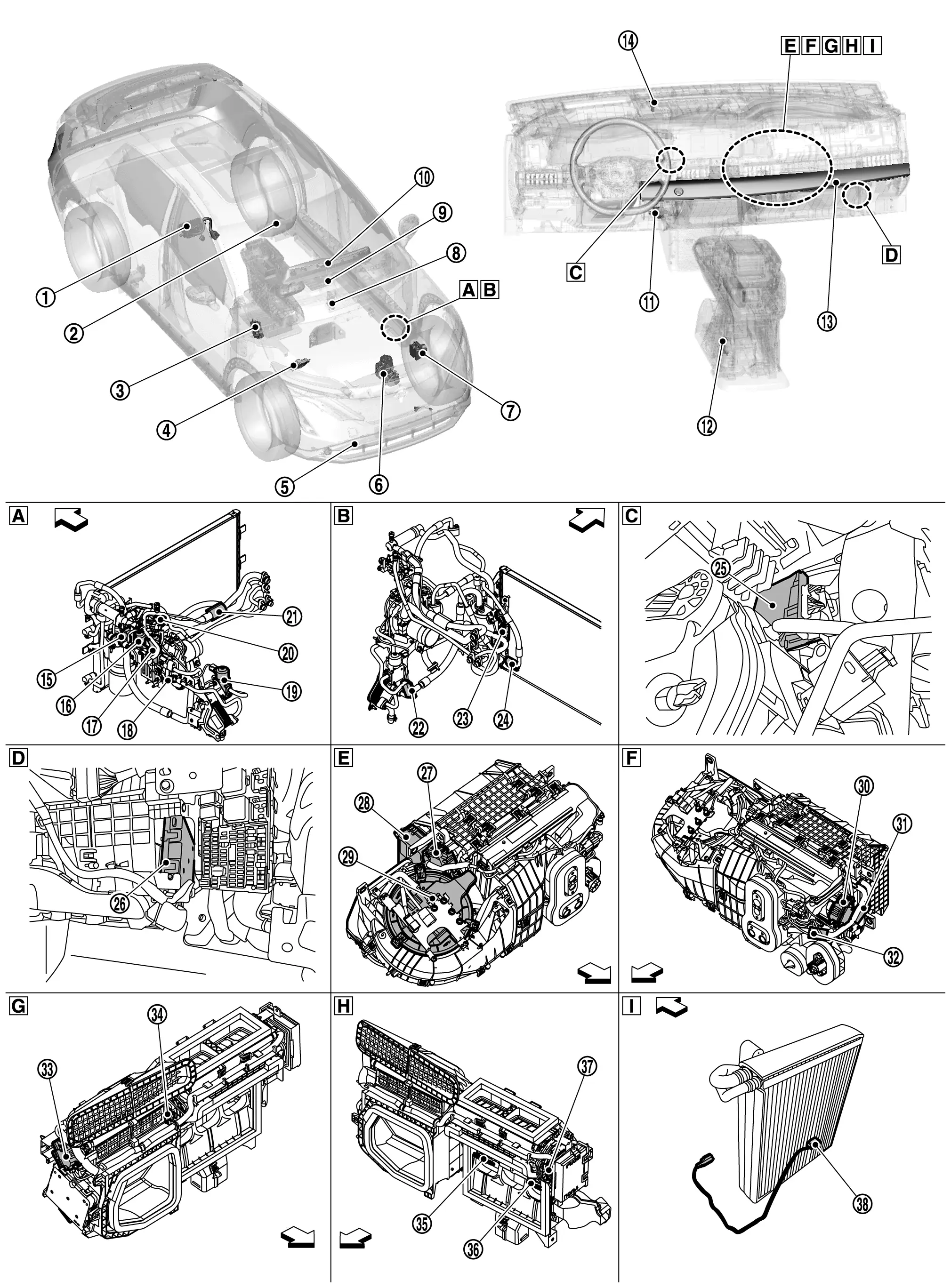
Component Parts Location
 |
Battery coolant heater |  |
Humidity sensor |  |
BCM Refer to Component Parts Location for detailed installation location. |
 |
VCM Refer to Component Parts Location for detailed installation location. |
 |
Ambient sensor |  |
Electric compressor |
 |
ABS actuator and electric unit (control unit) Refer to Component Parts Location for detailed installation location. |
 |
TCU Refer to Component Parts Location for detailed installation location. |
 |
AV control unit Refer to Component Parts Location for detailed installation location. |
 |
Combination meter |  |
In-Nissan Ariya vehicle sensor |  |
Rear mode door motor |
 |
A/C control |  |
Sunload sensor |  |
High pressure refrigerant channel switching valve |
 |
Electric expansion valve (cooler) |  |
Electric expansion valve (heater) |  |
Refrigerant temperature sensor (battery chiller outlet) |
 |
Expansion valve (battery chiller) |  |
Refrigerant pressure sensor |  |
Evaporator discharge refrigerant temperature sensor |
 |
Refrigerant temperature sensor (battery chiller inlet) |  |
Low pressure refrigerant channel switching valve |  |
Condenser discharge refrigerant temperature sensor |
 |
Heat pump control unit |  |
A/C auto amp. |  |
Air mix door motor (passenger side) |
 |
PTC heater |  |
Blower motor |  |
Air mix door motor (driver side) |
 |
Compressor discharge refrigerant temperature sensor |  |
Inner condenser discharge refrigerant temperature sensor |  |
Intake door motor |
 |
Front mode door motor (passenger side) |  |
PTC heater outlet air temperature sensor (passenger side) |  |
PTC heater outlet air temperature sensor (driver side) |
 |
Front mode door motor (driver side) |  |
Intake sensor | ||
 |
Left side of cooler pipe and hose |  |
Right side cooler pipe and hose |  |
Instrument lower cover is removed |
 |
Glove box is removed |  |
Right side of A/C unit assembly |  |
Left side of A/C unit assembly |
 |
Right side of intake & distribution box |  |
Left side of intake & distribution box |  |
Evaporator |
 |
Nissan Ariya Vehicle front |
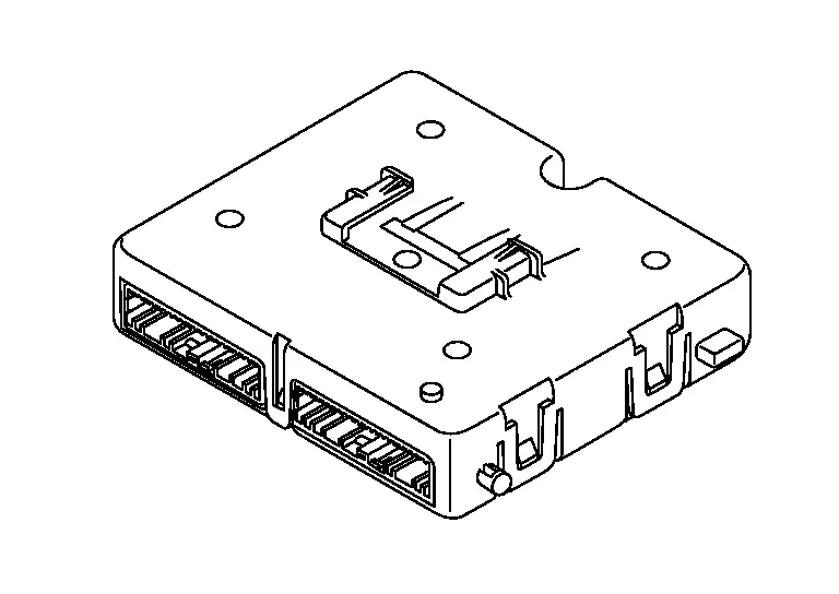
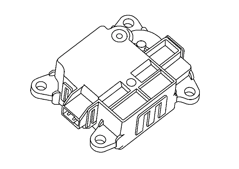
A/C Auto Amp.
COMPONENT FUNCTION WITHIN SYSTEM
A/C auto amp. controls the automatic air conditioning system by inputting and calculating signals from each sensor and each switch.
INDIVIDUAL COMPONENT FUNCTION
-
The A/C auto amp. consists of a microcomputer and input/output connectors for signals and power supply.
-
It has a CAN communications function, and it transmits and receives the necessary signals from each control module via CAN communication.
-
It has a LIN communications function, and transmits and receives signals to/from the each unit and each parts.
-
A/C auto amp. has self-diagnosis function. Diagnosis of automatic air conditioning system can be performed quickly.
COMPONENT OPERATION
Refer to System Description.
COMPONENT PARTS LOCATION
The A/C auto amp. is installed to the intake & distribution box.
Refer to Component Parts Location.
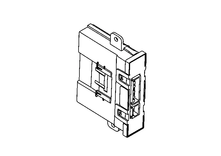
Heat Pump Control Unit
COMPONENT FUNCTION WITHIN SYSTEM
The heat pump control unit performs LIN communication with A/C auto amp.
INDIVIDUAL COMPONENT FUNCTION
-
The heat pump control unit consists of a microcomputer and input/output connectors for signals and power supply.
-
It has a CAN communications function, and it transmits and receives the necessary signals from each control module via CAN communication.
-
It has a LIN communications function, and transmits and receives signals to/from the A/C auto amp., PTC heater, electric compressor and battery coolant heater.
-
Converts the voltage values that are input from the each sensor to the temperature values, and transmits the temperature values to the A/C auto amp.
-
Controls the each valve and the each electric expansion valve by the request signal from A/C auto amp.
COMPONENT OPERATION
Refer to Heat Pump System Control.
COMPONENT PARTS LOCATION
The heat pump control unit is installed to the intake & distribution box.
Refer to Component Parts Location.
A/C Control
COMPONENT FUNCTION WITHIN SYSTEM
-
The A/C control
operates by LIN communication with the A/C auto amp., and the operation of the automatic air conditioning system can be arbitrarily set by the operate part  .
.
-
Indicates operation state of the automatic air conditioning system by the each switch indicator lamp color.
Switch Operating status Illumination state of the switch indicator color Intake switch Recirculation Orange Fresh air intake White AUTO switch Automatic control Orange Other then above White DEF switch DEF mode ON Orange DEF mode OFF White Rear window defogger switch Rear window defogger ON Orange Rear window defogger OFF White ON·OFF SW White illumination only
INDIVIDUAL COMPONENT FUNCTION
-
Detects that the finger touched switch panel surface of the A/C control.
-
When the pressure is detected on each switch, it is determined that the each switch has been operated.
-
The A/C control recognizes the operation status of each switch and sends it as an operate signal to the A/C auto amp. via LIN communication signal.
-
The operating status of the automatic air conditioning system is transmitted from the A/C auto amp. via LIN communication.
COMPONENT OPERATION
-
Detects A/C control operation then give a feedback by vibration.
-
Indicates the each switch on the surface of the A/C control by the power switch ON.
-
The operation status of each switch is detected by the control and is transmitted as an operation signal to the A/C auto amp. via LIN communication.
-
For details the function of each switch. Refer to Switch Name and Function.
COMPONENT PARTS LOCATION
The A/C control is installed to the instrument panel assembly.
Refer to Component Parts Location.
Ambient Sensor
COMPONENT FUNCTION WITHIN SYSTEM
-
The ambient sensor detects the temperature of the ambient air, and transmits the ambient sensor signal to the combination meter.
-
This signal is transmitted from the combination meter to the A/C auto amp. via CAN communication and is used in air conditioning system.
INDIVIDUAL COMPONENT FUNCTION
The ambient sensor measures the ambient air temperature.
COMPONENT OPERATION
The ambient sensor measures the ambient air temperature, and transmits the ambient sensor signal to the combination meter. This sensor uses a thermistor with electrical resistance that decreases as the temperature increases.

COMPONENT PARTS LOCATION
The ambient sensor is installed to the active grille shutter.
Refer to Component Parts Location.
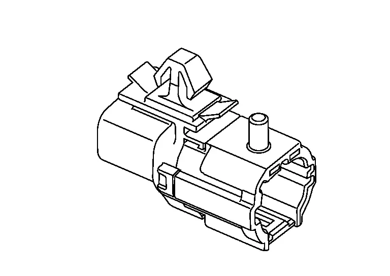
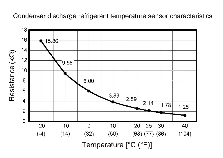
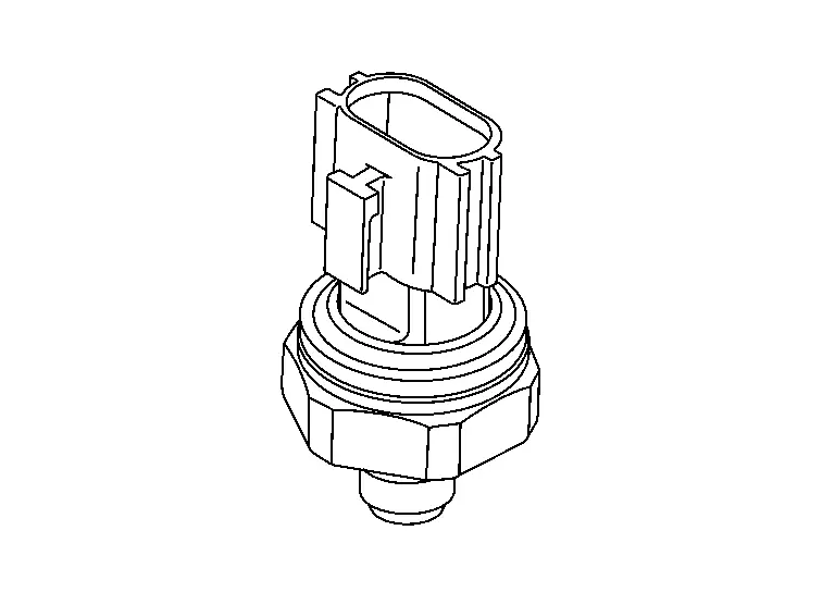
Condenser Discharge Refrigerant Temperature Sensor
COMPONENT FUNCTION WITHIN SYSTEM
The condenser discharge refrigerant temperature sensor converts the refrigerant temperature detected with thermistor into the voltage, and the heat pomp control unit inputs this voltage.
INDIVIDUAL COMPONENT FUNCTION
Condenser discharge refrigerant temperature sensor measures the temperature of refrigerant that is discharged from the condenser between the condenser and the evaporator and battery coolant chiller.
COMPONENT OPERATION
The sensor uses a thermistor which is sensitive to the change in temperature. The electrical resistance of the thermistor decreases as temperature increases.
COMPONENT PARTS LOCATION
Condenser discharge refrigerant temperature sensor is located on the pipe part of the condenser outlet.
Refer to Component Parts Location.
Compressor Discharge Refrigerant Temperature Sensor
COMPONENT FUNCTION WITHIN SYSTEM
The compressor discharge refrigerant temperature sensor converts the refrigerant temperature detected with thermistor into the voltage, and the heat pomp control unit inputs this voltage.
INDIVIDUAL COMPONENT FUNCTION
Compressor discharge refrigerant temperature sensor measures the temperature of refrigerant that is discharged from the compressor between the compressor and the inner condenser.
COMPONENT OPERATION
The sensor uses a thermistor which is sensitive to the change in temperature. The electrical resistance of the thermistor decreases as temperature increases.

COMPONENT PARTS LOCATION
Compressor discharge refrigerant temperature sensor is located on the pipe part of the compressor outlet.
Refer to Component Parts Location.
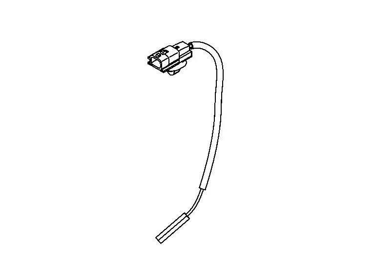
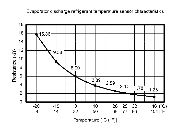
Evaporator Discharge Refrigerant Temperature Sensor
COMPONENT FUNCTION WITHIN SYSTEM
The evaporator discharge refrigerant temperature sensor converts the refrigerant temperature detected with thermistor into the voltage, and the heat pomp control unit inputs this voltage.
INDIVIDUAL COMPONENT FUNCTION
Evaporator discharge refrigerant temperature sensor measures the temperature of refrigerant that is discharged from the evaporator between the evaporator and the compressor.
COMPONENT OPERATION
The sensor uses a thermistor which is sensitive to the change in temperature. The electrical resistance of the thermistor decreases as temperature increases.
COMPONENT PARTS LOCATION
Evaporator discharge refrigerant temperature sensor is located on the pipe part of the evaporator outlet.
Refer to Component Parts Location.
Humidity Sensor
COMPONENT FUNCTION WITHIN SYSTEM
Humidity sensor measures windshield temperature and passenger room humidity so that fogging on windshield is judged.
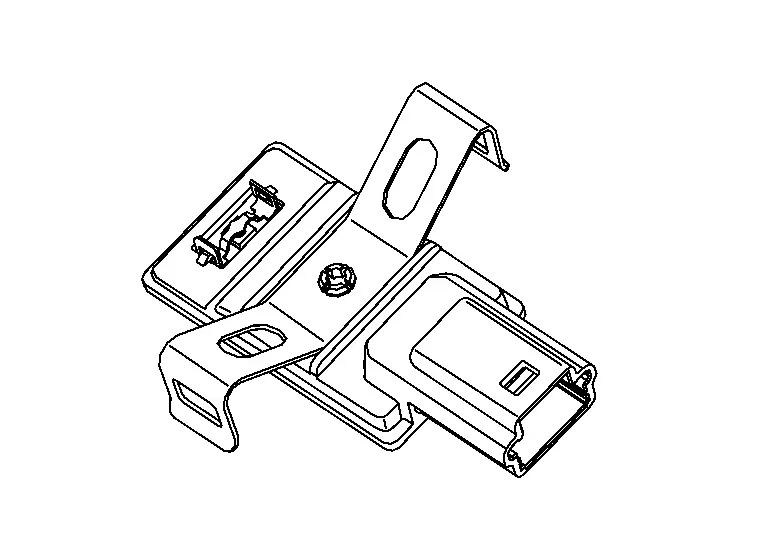
INDIVIDUAL COMPONENT FUNCTION
Humidity sensor detect windshield temperature and passenger room humidity.
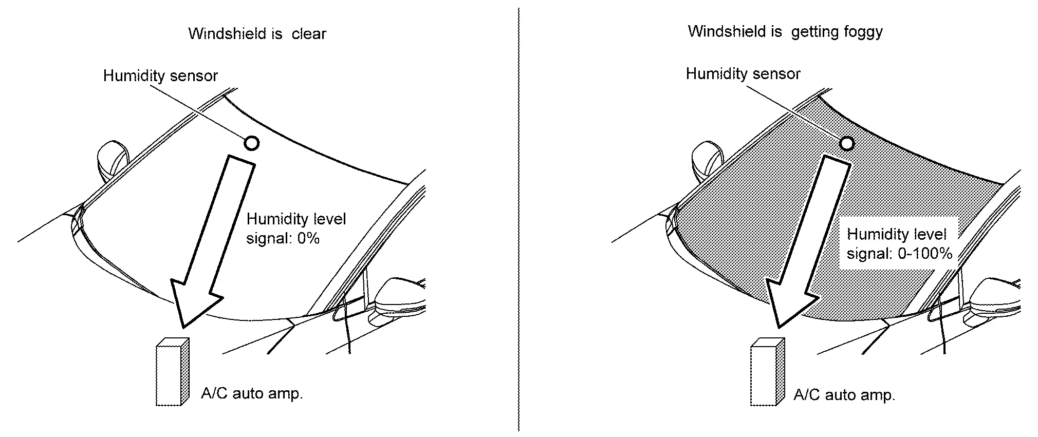
COMPONENT OPERATION
Humidity sensor changes the output of the humidity level signal from 0% to 100% according to the fogged up of the windshield glass and sends it to the A/C auto amp. via LIN communication. When there is no fogging on the windshield glass, it is transmitted at 0% output signal, and when fogging is detected, it is transmitted at 10% to 100% output signals depending on the degree of fogging. A/C auto amp. controls the fogging prevention mode (fresh air intake and ALL mode position the air outlets shift to ventilation, and when the humidity becomes higher, it becomes DEF mode position) automatically operates when fogging is detected.
COMPONENT PARTS LOCATION
The humidity sensor is installed to the windshield glass.
Refer to Component Parts Location.
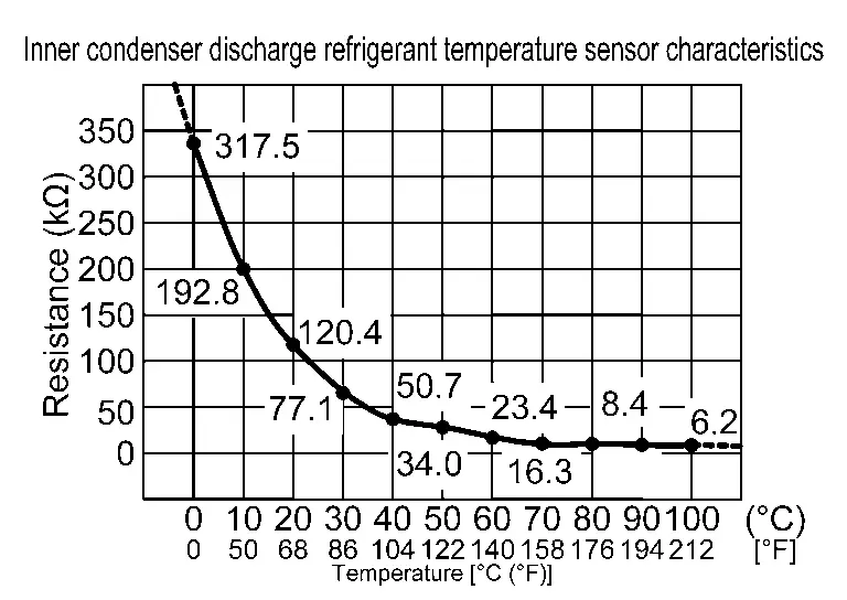
Inner Condenser Discharge Refrigerant Temperature Sensor
COMPONENT FUNCTION WITHIN SYSTEM
The inner condenser discharge refrigerant temperature sensor converts the refrigerant temperature detected with thermistor into the voltage, and the heat pomp control unit inputs this voltage.
INDIVIDUAL COMPONENT FUNCTION
Inner condenser discharge refrigerant temperature sensor measures the temperature of refrigerant that is discharged from the inner condenser between the inner condenser and the condenser.
COMPONENT OPERATION
The sensor uses a thermistor which is sensitive to the change in temperature. The electrical resistance of the thermistor decreases as temperature increases.
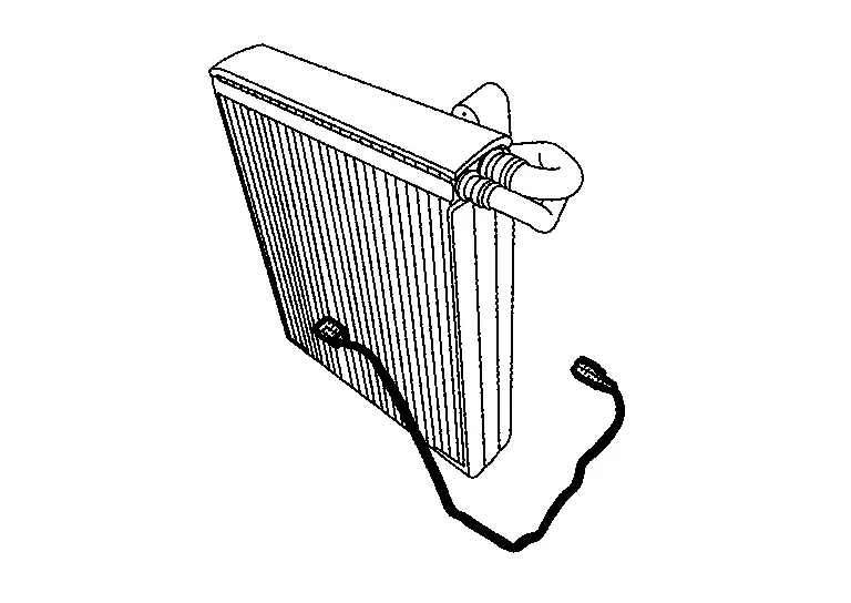
COMPONENT PARTS LOCATION
Inner condenser discharge refrigerant temperature sensor is located on the pipe part of the inner condenser outlet.
Refer to Component Parts Location.
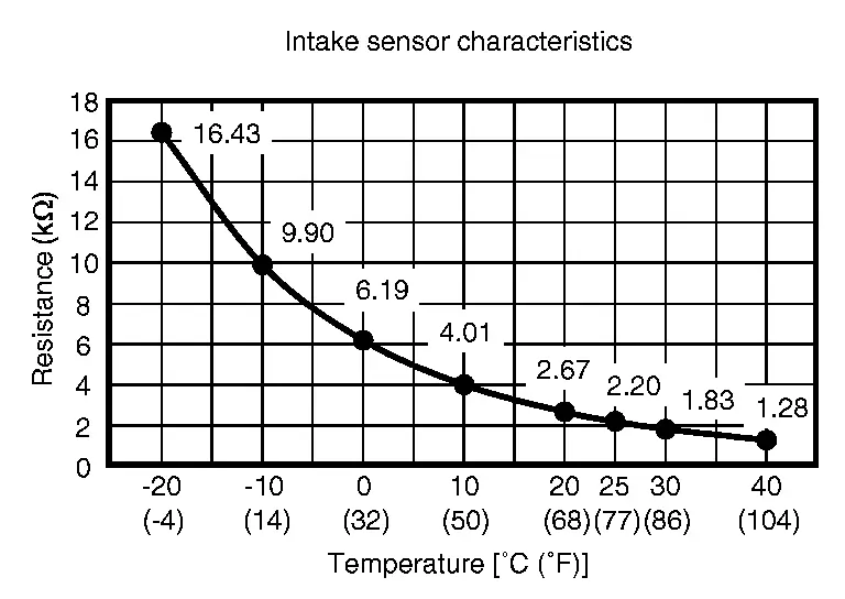
Intake Sensor
COMPONENT FUNCTION WITHIN SYSTEM
The intake sensor converts the evaporator surface temperature detected with thermistor into the voltage, and the A/C auto amp. inputs this voltage.
INDIVIDUAL COMPONENT FUNCTION
Intake sensor measures evaporator temperature (through air temperature).
COMPONENT OPERATION
The sensor uses a thermistor which is sensitive to the change in temperature. The electrical resistance of the thermistor decreases as temperature increases.
COMPONENT PARTS LOCATION
Intake sensor is located on the evaporator.
Refer to Component Parts Location.
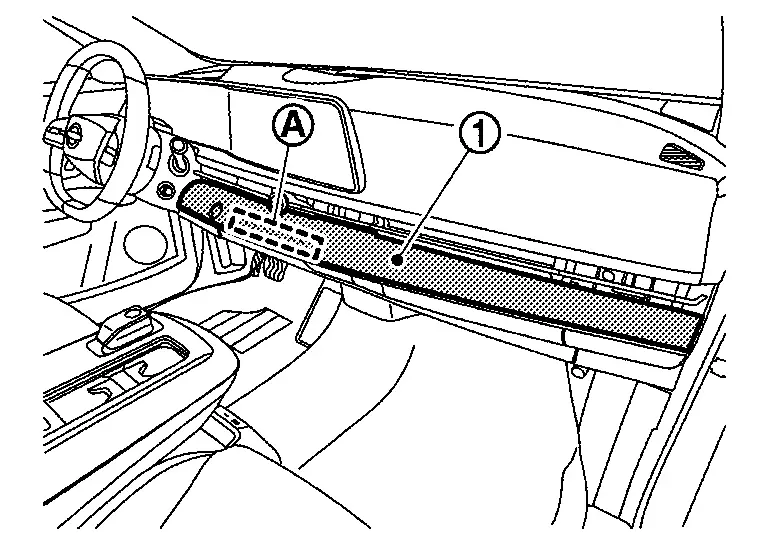
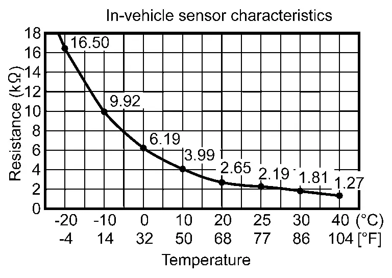
In-vehicle Sensor
COMPONENT FUNCTION WITHIN SYSTEM
The in-vehicle sensor detects the temperature of the in-vehicle air that is taken in by the built-in fan motor, and transmits the in-Nissan Ariya vehicle sensor signal to the A/C auto amp.
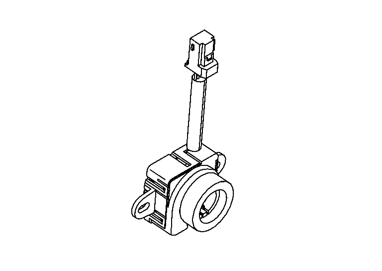
INDIVIDUAL COMPONENT FUNCTION
The in-vehicle sensor measures the temperature of the in-vehicle air taken in by the built-in fan motor.
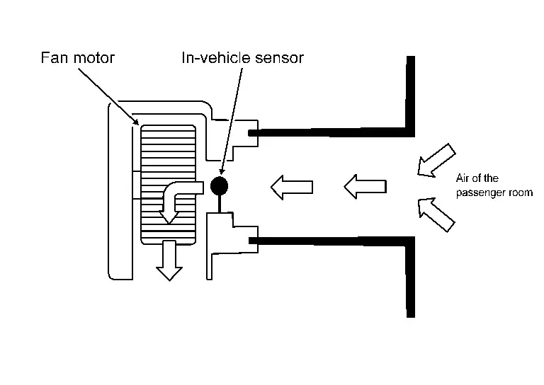
COMPONENT OPERATION
The in-vehicle sensor measures the temperature of the in-vehicle air that is taken in by the built-in fan motor, and transmits the in-Nissan Ariya vehicle sensor signal to the A/C auto amp. This sensor uses a thermistor with electrical resistance that decreases as the temperature increases.
 NOTE:
NOTE:
The built-in fan motor constantly sucks the air of the passenger room into the in-Nissan Ariya vehicle sensor.
COMPONENT PARTS LOCATION
The in-vehicle sensor is installed to the instrument lower panel.
Refer to Component Parts Location.
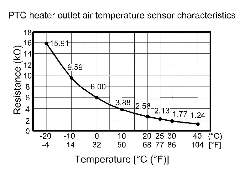
PTC Heater Outlet Air Temperature Sensor
COMPONENT FUNCTION WITHIN SYSTEM
PTC heater outlet air temperature sensor (driver side / passenger side) converts the air temperature immediately after the air passes the PTC heater core detected with thermistor into the voltage, and the A/C auto amp. inputs this voltage.
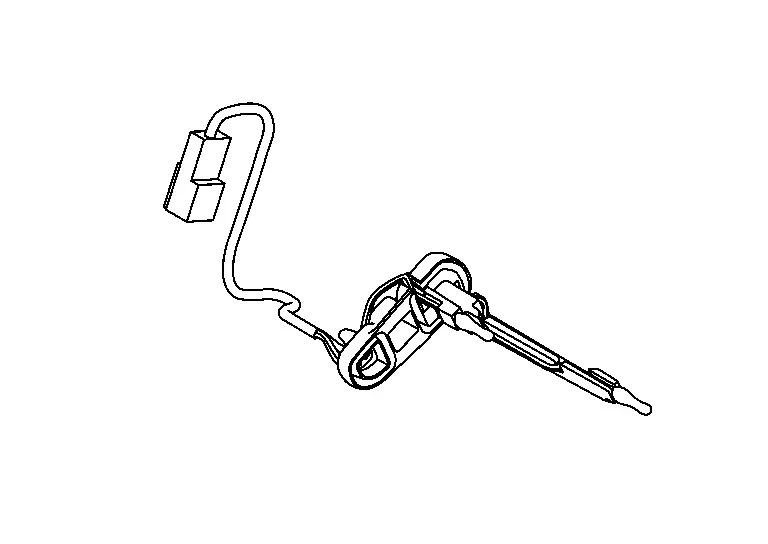
INDIVIDUAL COMPONENT FUNCTION
PTC heater outlet air temperature sensor (driver side / passenger side) measures the air temperature immediately after the air passes the PTC heater core.
COMPONENT OPERATION
The sensor uses a thermistor which is sensitive to the change in temperature. The electrical resistance of the thermistor decreases as temperature increases.
COMPONENT PARTS LOCATION
PTC heater outlet air temperature sensor (driver side / passenger side) is installed to the intake & distribution box.
Refer to Component Parts Location.
Refrigerant Pressure Sensor
COMPONENT FUNCTION WITHIN SYSTEM
-
The refrigerant pressure sensor converts high-pressure side refrigerant pressure into voltage and outputs it to VCM.
-
This value is transmitted from the VCM to the A/C auto amp. via CAN communication and is used in electric compressor control and cooling fan operation request control.
INDIVIDUAL COMPONENT FUNCTION
The refrigerant pressure sensor converts refrigerant pressure into voltage.
COMPONENT OPERATION
-
The refrigerant pressure sensor is a capacitance type sensor. It consists of a pressure detection area and a signal processing area.
-
The pressure detection area, which is a variable capacity condenser, changes internal static capacitance according to pressure force.
-
The signal processing area detects the static capacitance of the pressure detection area, converts the static capacitance into a voltage value, and transmits the voltage value to VCM.
-
The output voltage increases as the refrigerant pressure rises.

COMPONENT PARTS LOCATION
The refrigerant pressure sensor is installed to the high-pressure cooler pipe assembly.
Refer to Component Parts Location.
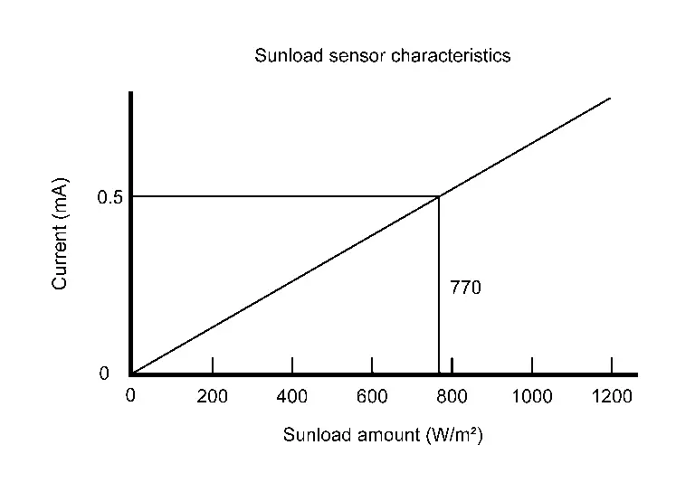
Sunload Sensor
COMPONENT FUNCTION WITHIN SYSTEM
Sunload sensor converts sunload amount to voltage signal by photodiode and transmits to A/C auto amp.
INDIVIDUAL COMPONENT FUNCTION
Sunload sensor measures sunload amount.
COMPONENT OPERATION
The sunload sensor measures the sunload and outputs the sunload sensor signal to the A/C auto amp. This sensor uses a photodiode with an electrical current that increases as the sunload increases.
COMPONENT PARTS LOCATION
The sunload sensor is installed to the instrument garnish.
Refer to Component Parts Location.
Air Mix Door Motor
COMPONENT FUNCTION WITHIN SYSTEM
It operates by multiplex communication control (LIN) with the A/C auto amp. and controls the position of the air mix door (drive side / passenger side).
INDIVIDUAL COMPONENT FUNCTION
Rotation of motor is transmitted to air mix door (drive side / passenger side). Air flow temperature is switched.
COMPONENT OPERATION
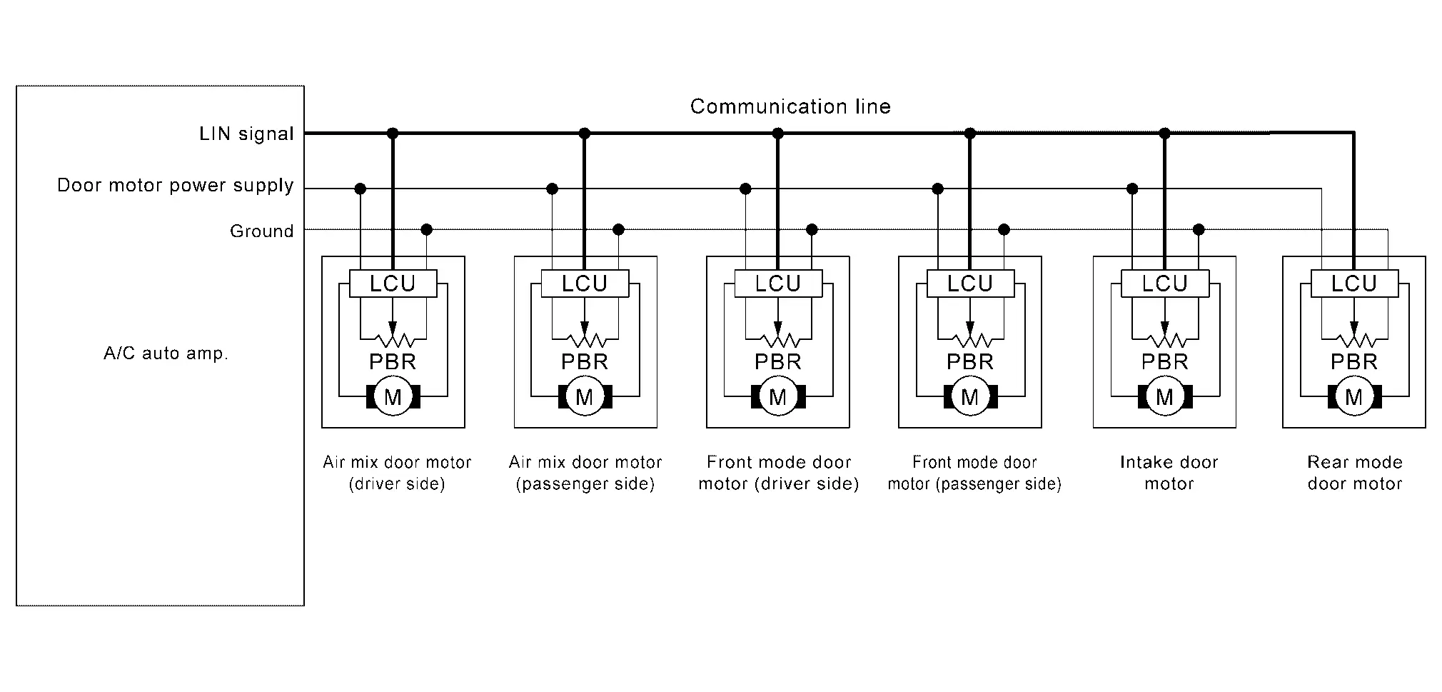
-
LCU (Local Control Unit) is built into air mix door motor (drive side / passenger side). And detects door position by PBR (Potentio Balance Resistor).
-
A/C auto amp. communicates with each LCU via LIN communication line. And receives air mix door (drive side / passenger side) position feedback signal from LCU.
-
Rotation of motor is transmitted to air mix door (drive side / passenger side). Air flow temperature is switched.
-
LCU transmits the signal of door movement completion to A/C auto amp., when the door movement is completed.
COMPONENT PARTS LOCATION
The air mix door motor (drive side / passenger side) is installed to the A/C unit assembly.
Refer to Component Parts Location.
Intake Door Motor
COMPONENT FUNCTION WITHIN SYSTEM
It operates by multiplex communication control (LIN) with the A/C auto amp. and controls the position of the intake door.
INDIVIDUAL COMPONENT FUNCTION
Rotation of motor is transmitted to intake door. Air inlet is switched.
COMPONENT OPERATION
-
LCU (Local Control Unit) is built into intake door motor. And detects door position by PBR (Potentio Balance Resistor).
-
A/C auto amp. communicates with each LCU via communication line. And receives intake door position feedback signal from LCU.
-
Rotation of motor is transmitted to intake door. Air inlet is switched.
-
LCU transmits the signal of door movement completion to A/C auto amp., when the door movement is completed.
COMPONENT PARTS LOCATION
The intake door motor is installed to the intake & distribution box.
Refer to Component Parts Location.
Front Mode Door Motor
COMPONENT FUNCTION WITHIN SYSTEM
It operates by multiplex communication control (LIN) with the A/C auto amp. and controls the position of the each front mode door.
INDIVIDUAL COMPONENT FUNCTION
Rotation of motor is transmitted to each front mode door. Air outlet is switched.
COMPONENT OPERATION
-
LCU (Local Control Unit) is built into front mode door motor (drive side / passenger side). And detects door position by PBR (Potentio Balance Resistor).
-
A/C auto amp. communicates with each LCU via communication line. And receives each front mode door position feedback signal from LCU.
-
Rotation of motor is transmitted to each front mode door. Air outlet is switched.
-
LCU transmits the signal of door movement completion to A/C auto amp., when the door movement is completed.
COMPONENT PARTS LOCATION
The front mode door motor (drive side / passenger side) is installed to the intake & distribution box.
Refer to Component Parts Location.
Rear Mode Door Motor
COMPONENT FUNCTION WITHIN SYSTEM
It operates by multiplex communication control (LIN) with the A/C auto amp. and controls the position of the rear mode door.
INDIVIDUAL COMPONENT FUNCTION
Rotation of motor is transmitted to rear mode door. Air outlet is switched.
COMPONENT OPERATION
-
LCU (Local Control Unit) is built into rear mode door motor. And detects door position by PBR (Potentio Balance Resistor).
-
A/C auto amp. communicates with each LCU via communication line. And receives rear mode door position feedback signal from LCU.
-
Rotation of motor is transmitted to rear mode door. Air outlet is switched.
-
LCU transmits the signal of door movement completion to A/C auto amp., when the door movement is completed.
COMPONENT PARTS LOCATION
The rear mode door motor is installed to the rear ventilator duct.
Refer to Component Parts Location.
Blower Motor
COMPONENT FUNCTION WITHIN SYSTEM
The rotation speed is changed according to the voltage controlled by the A/C auto amp. and the air flow rate is controlled.
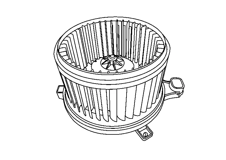
INDIVIDUAL COMPONENT FUNCTION
The motor with the sirocco fan rotates, taking in-vehicle or ambient air and sending it into the passenger room.
COMPONENT OPERATION
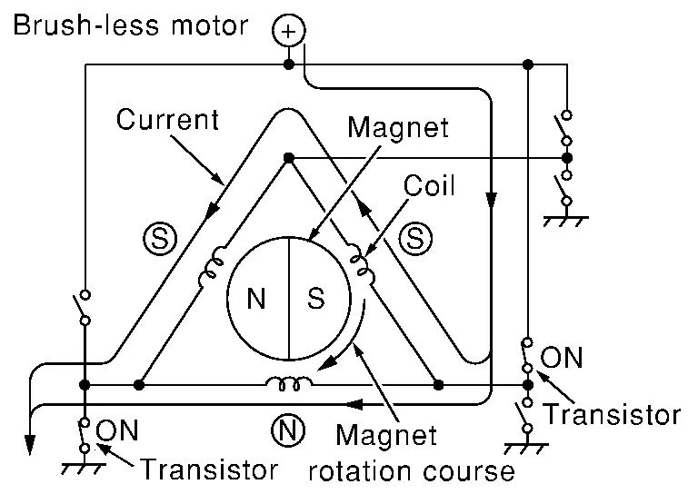
The blower motor adopts the brush-less.
NOTE:
-
Brush motor rotates the coil while the brush functions as contact point.
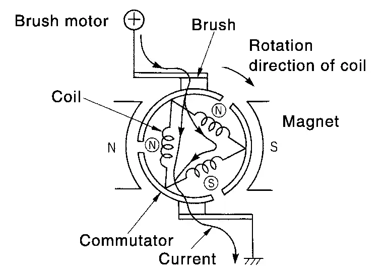
-
Brush-less motor, the magnet part rotates.
COMPONENT PARTS LOCATION
The blower motor is installed to the A/C unit assembly.
Refer to Component Parts Location.
Electric Compressor
COMPONENT FUNCTION WITHIN SYSTEM
Inverter controls the motor according to the requests from the A/C auto amp. or VCM, and changes the compressor drive and refrigerant discharge amount.
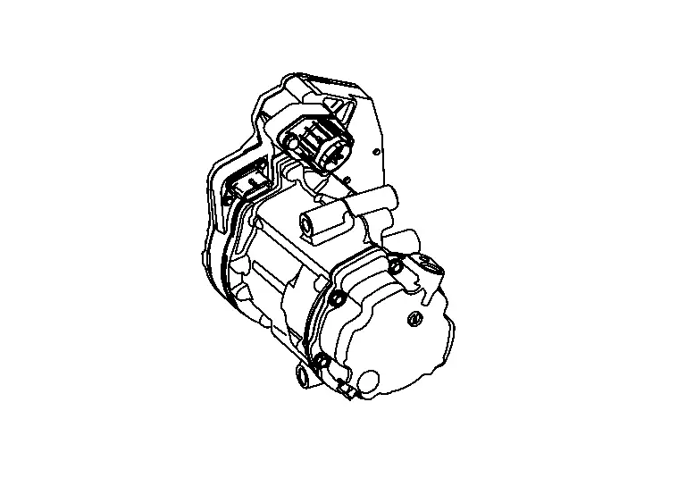
INDIVIDUAL COMPONENT FUNCTION
-
An electric scroll compressor is used.
-
A 3-phase output inverter with IPMNote is used.
-
The inverter is adopted to IPMNote for smaller size and improved reliability.
NOTE:
-
IPM (Intelligent Power Module) is the element which delivered power device equivalent to IGBT and the protection feature of the circuit to one package.
-
IGBT (Insulated Gate Bipolar Transistor) is a transistor which is suitable for high voltages and large currents and which can control large electrical power using a small gate voltage.
-
COMPONENT OPERATION
The structure integrates the inverter, compressor, and motor, allowing compressor to operate at any speed.
Inverter
-
The inverter communicates with A/C auto amp., and uses PWM controlNote to control the motor speed via the drive circuit.
NOTE:
-
PWM (Pulse Width Modulation) is a system that controls current and voltage by changing the duty ratio of a constant frequency pulse wave.
-
PWM is used as the adjustment method of output voltage when inverter is used as a power supply for controlling motor speed.
-
PWM changes voltage application time (pulse width) using a semiconductor element and controls motor speed.
-
-
The IPM contains an internal protection circuit, and uses the inverter control circuit to monitor for an increase in motor drive circuit temperature in order to prevent circuit overheating.
-
Adopts the HVIL (High-Voltage Interlock Loop) circuit inside the electric compressor, and CPU monitors the HVIL circuit.
NOTE:
HVIL is composed of the loop circuit in the electric compressor and the high pressure system connector, and detects connector poor connection, etc. due to open circuit.
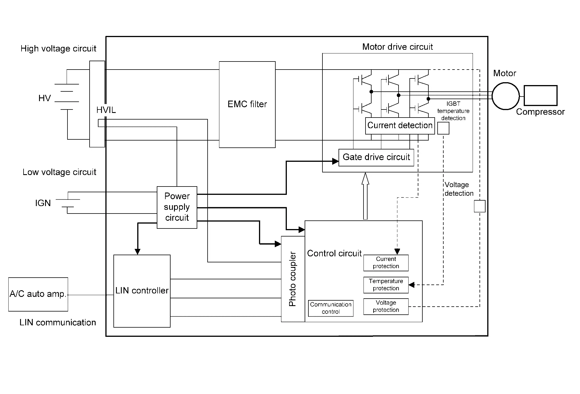
Motor
The motor uses a DC brush-less motor, with speed control performed by the inverter drive circuit.
NOTE:
-
Brush motor rotates the coil while the brush functions as contact point.
-
Brush-less motor, the magnet part rotates.
COMPONENT PARTS LOCATION
The electric compressor is installed to the left side of front traction motor.
Refer to Component Parts Location.
PTC Heater
COMPONENT FUNCTION WITHIN SYSTEM
-
A PTC heater is used as the heat source for heating.
-
Provides internal control circuit and performs LIN communication with A/C auto amp.
INDIVIDUAL COMPONENT FUNCTION
Heat element is heated and air flow temperature is increased.
COMPONENT OPERATION
-
The PTC heater utilizes a PTC element is adopted.
-
Based on the signals from A/C auto amp., the microcomputer inside PTC heater controls the heater output by PWM.
NOTE:
-
PWM (Pulse Width Modulation) is a system that controls current and voltage by changing the duty ratio of a constant frequency pulse wave.
-
PWM is used as the adjustment method of output voltage when inverter is used as a power supply for controlling motor speed.
-
PWM changes voltage application time (pulse width) using a semiconductor element and controls PTC heater.
-
-
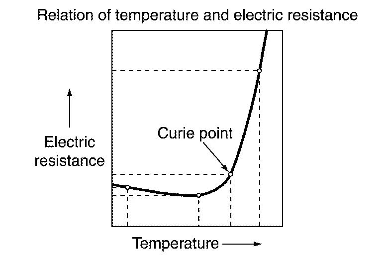
PTC stands for "Positive Temperature Coefficient", and is a ceramic material with barium titanate as the primary component.
-
When current is applied, it heats up. Upon reaching a certain temperature (curie temperature) the resistance suddenly increases, limiting the current, and maintaining a constant amount of heating.
COMPONENT PARTS LOCATION
The PTC heater is installed to the A/C unit assembly.
Refer to Component Parts Location.
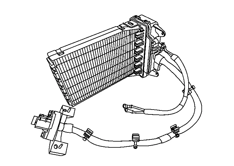
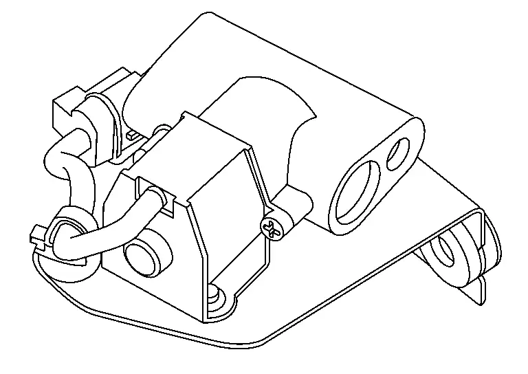
Electric Expansion Valve (Cooler)
NOTE:
The electronic expansion valve is an expansion valve that open or close the refrigerant flow path by an electric signal.
COMPONENT FUNCTION WITHIN SYSTEM
When the drive signal from the heat pump control unit is input into the motor, the motor rotates corresponding to the drive signal and control at the electric expansion valve open or close.
INDIVIDUAL COMPONENT FUNCTION
Rotate the motor to open or close the expansion valve.
COMPONENT OPERATION
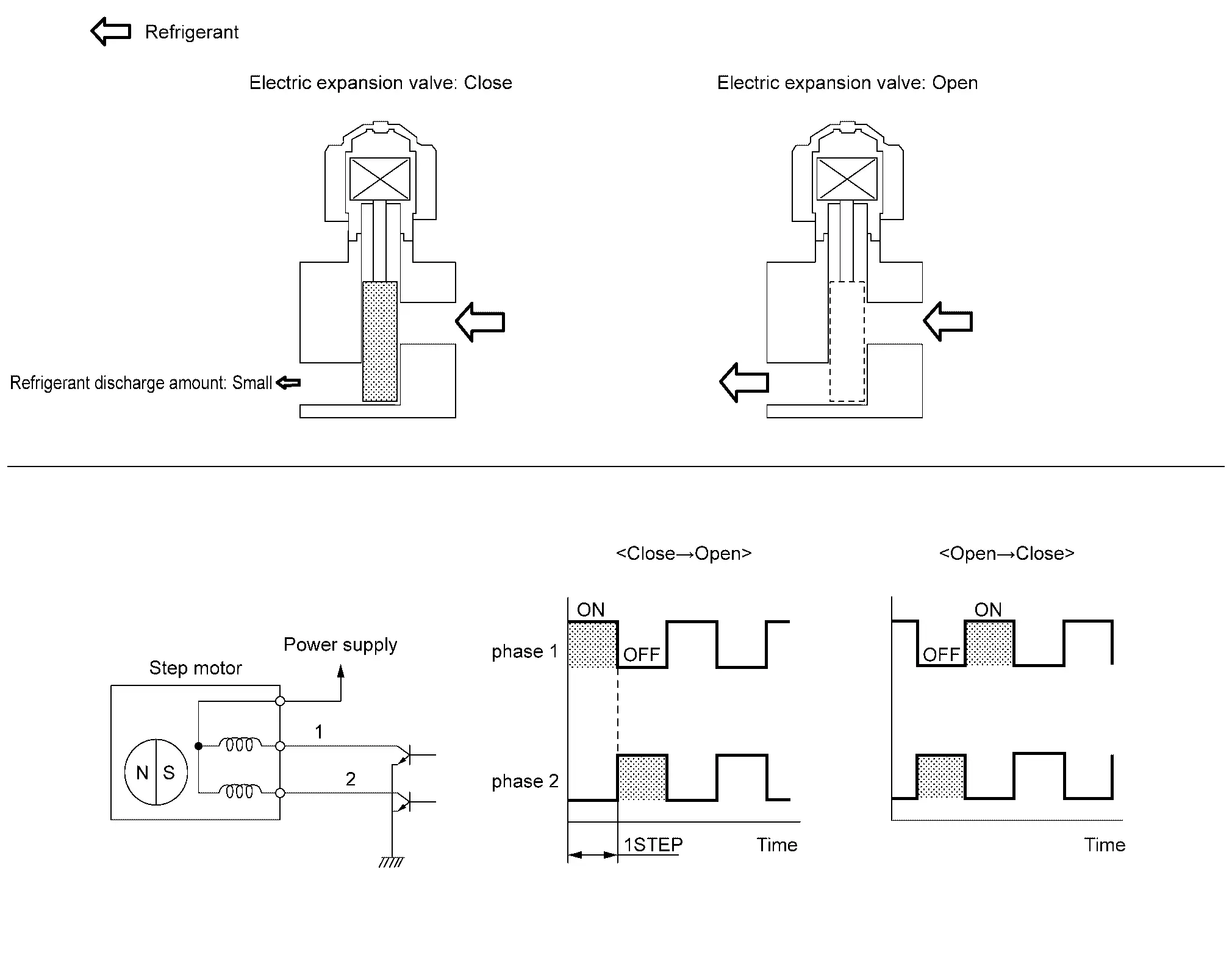
The expansion valve is open or close by the control signal from the heat pump control unit to control the refrigerant flow rate.
COMPONENT PARTS LOCATION
Electronic expansion valve (cooler) is installed to the high-pressure cooler pipe assembly.
Refer to Component Parts Location.
Electric Expansion Valve (Heater)
NOTE:
The electronic expansion valve is an expansion valve that open or close the refrigerant flow path by an electric signal.
COMPONENT FUNCTION WITHIN SYSTEM
When the drive signal from the heat pump control unit is input into the motor, the motor rotates corresponding to the drive signal and control at the electric expansion valve open or close.
INDIVIDUAL COMPONENT FUNCTION
Rotate the motor to open or close the expansion valve.
COMPONENT OPERATION
The expansion valve is open or close by the control signal from the heat pump control unit to control the refrigerant flow rate.
COMPONENT PARTS LOCATION
Electronic expansion valve (heater) is installed to the high-pressure cooler pipe assembly.
Refer to Component Parts Location.
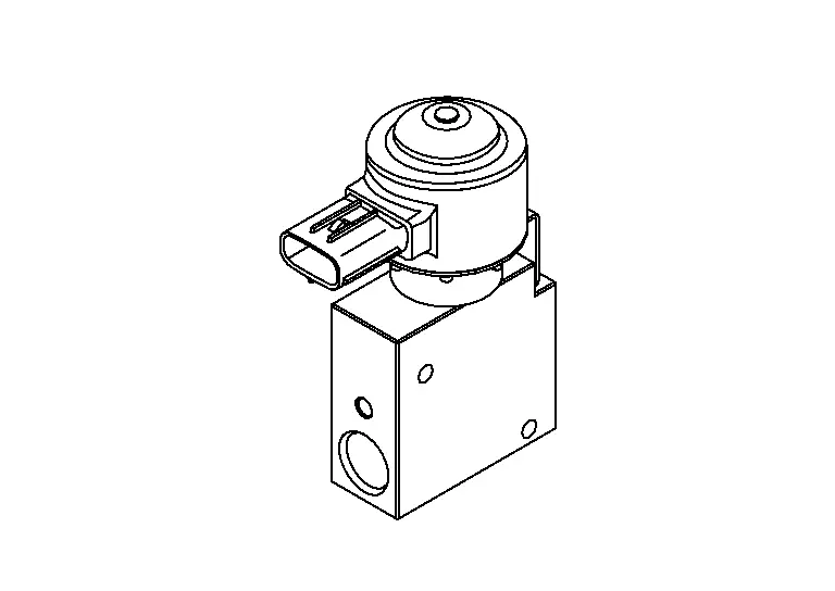
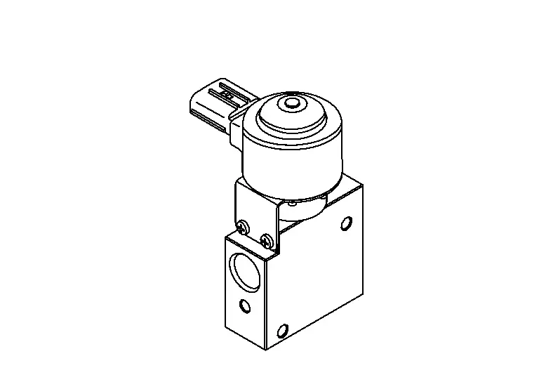
High Pressure Refrigerant Channel Switching Valve
COMPONENT FUNCTION WITHIN SYSTEM
It operates by the drive signal from the heat pump control unit and controls the open or close of the valve.
INDIVIDUAL COMPONENT FUNCTION
Turn the solenoid valve on/off to open or close the valve.
COMPONENT OPERATION
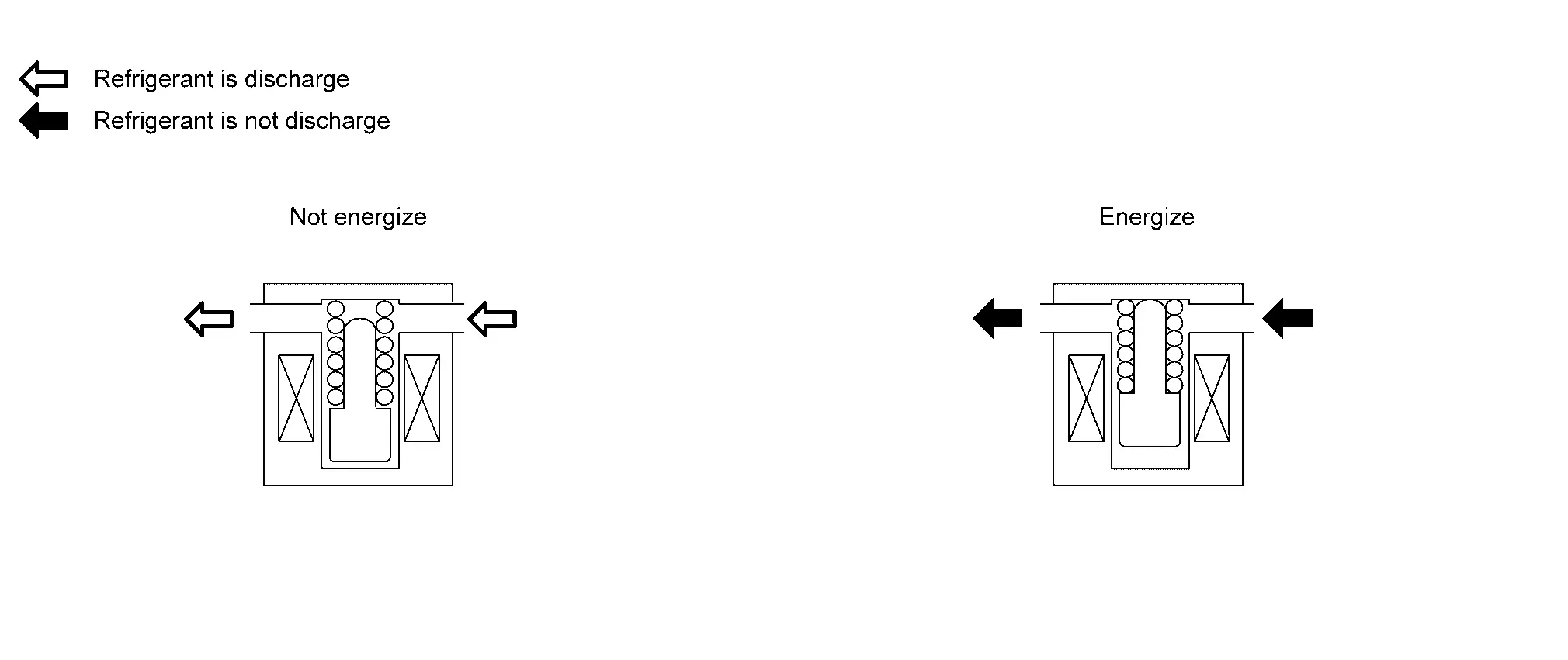
The valve is open or close by the control signal from heat pump control unit to control the refrigerant flow path from inner condenser to evaporator and battery coolant chiller.
COMPONENT PARTS LOCATION
High pressure refrigerant channel switching valve is installed to the high-pressure cooler pipe assembly.
Refer to Component Parts Location.
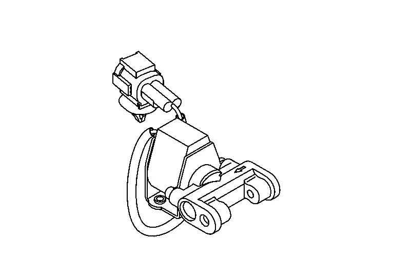
Low Pressure Refrigerant Channel Switching Valve
COMPONENT FUNCTION WITHIN SYSTEM
It operates by the drive signal from the heat pump control unit and controls the open or close of the valve.
INDIVIDUAL COMPONENT FUNCTION
Turn the solenoid valve on/off to open or close the valve.
COMPONENT OPERATION
The valve is open or close by the control signal from heat pump control unit to control the refrigerant flow path from condenser to electric compressor.
COMPONENT PARTS LOCATION
Low pressure refrigerant channel switching valve is installed to the accumulator assembly.
Refer to Component Parts Location.
System. Automatic Air Conditioning System Nissan Ariya 2023
System Description
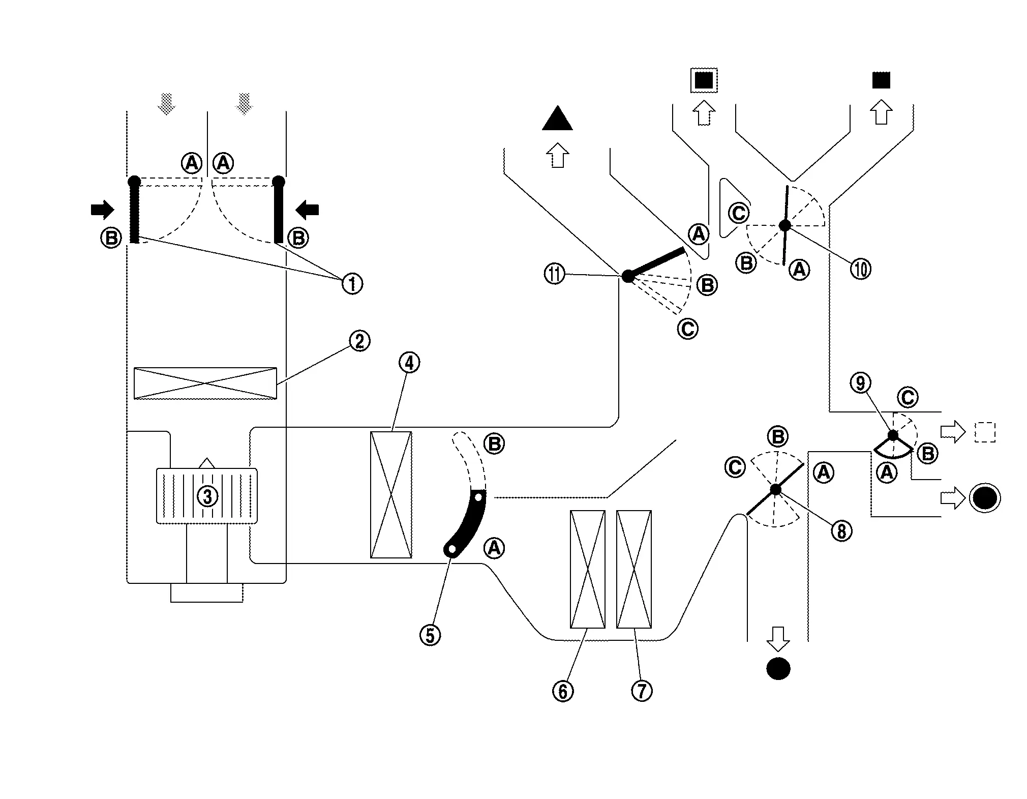
SYSTEM DIAGRAM
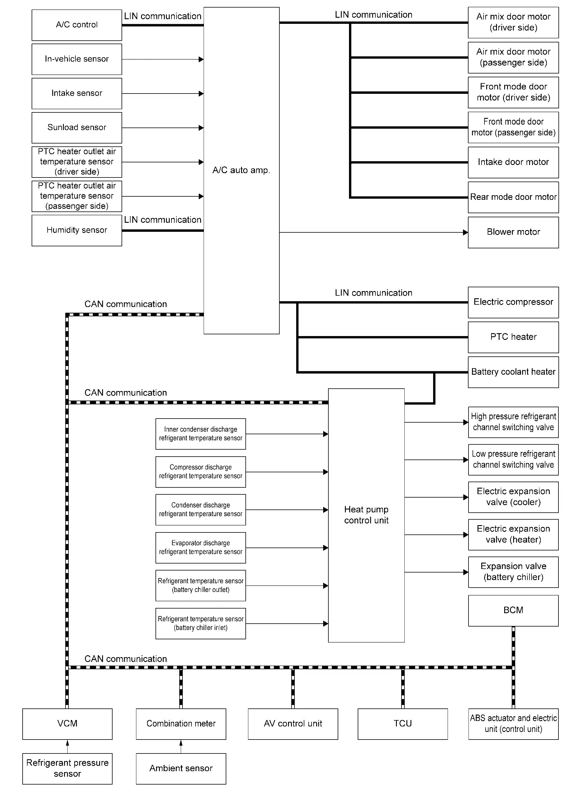
| Component | Function |
|---|---|
| ABS actuator and electric unit (control unit) | ABS actuator and electric unit (control unit) transmits Nissan Ariya vehicle speed signal to A/C auto amp. via CAN communication line. |
| AV control unit |
|
| BCM |
|
| TCU | Transmits a remote climate control request signal and remote climate control setting signal that is received by the Telematics system to BCM via CAN communication line. |
| VCM |
|
| Combination meter | Combination meter transmits ambient temperature signal to A/C auto amp. via CAN communication line. |
| A/C auto amp. | A/C Auto Amp. |
| Heat pump control unit | Heat Pump Control Unit |
| A/C control | A/C Control |
| Ambient sensor | Ambient Sensor |
| Condenser discharge refrigerant temperature sensor | Condenser Discharge Refrigerant Temperature Sensor |
| Compressor discharge refrigerant temperature sensor | Compressor Discharge Refrigerant Temperature Sensor |
| Evaporator discharge refrigerant temperature sensor | Evaporator Discharge Refrigerant Temperature Sensor |
| Humidity sensor | Humidity Sensor |
| Inner condenser discharge refrigerant temperature sensor | Inner Condenser Discharge Refrigerant Temperature Sensor |
| Intake sensor | Intake Sensor |
| In-Nissan Ariya vehicle sensor | In-vehicle Sensor |
| PTC heater outlet air temperature sensor (driver side) | PTC Heater Outlet Air Temperature Sensor |
| PTC heater outlet air temperature sensor (passenger side) | PTC Heater Outlet Air Temperature Sensor |
| Refrigerant pressure sensor | Refrigerant Pressure Sensor |
| Sunload sensor | Sunload Sensor |
| Air mix door motor (driver side) | Air Mix Door Motor |
| Air mix door motor (passenger side) | Air Mix Door Motor |
| Intake door motor | Intake Door Motor |
| Front mode door motor (driver side) | Front Mode Door Motor |
| Front mode door motor (passenger side) | Front Mode Door Motor |
| Rear mode door motor | Rear Mode Door Motor |
| Blower motor | Blower Motor |
| Electric compressor | Electric Compressor |
| PTC heater | PTC Heater |
| Electric expansion valve (cooler) | Electric Expansion Valve (Cooler) |
| Electric expansion valve (heater) | Electric Expansion Valve (Heater) |
| High pressure refrigerant channel switching valve | High Pressure Refrigerant Channel Switching Valve |
| Low pressure refrigerant channel switching valve | Low Pressure Refrigerant Channel Switching Valve |
| Refrigerant temperature sensor (battery chiller inlet) | Component Description |
| Refrigerant temperature sensor (battery chiller outlet) | Component Description |
| Expansion valve (battery chiller) | Component Description |
| Battery coolant heater | Component Description |
INPUT/OUTPUT SIGNAL
| Component | Signal status |
|---|---|
| ABS actuator and electric unit (control unit) | Transmits the Nissan Ariya vehicle speed signal to A/C auto amp. via CAN communication. |
| AV control unit |
|
| BCM |
|
| VCM |
|
| TCU |
|
| Combination meter | Transmits the ambient temperature signal to A/C auto amp. via CAN communication. |
| Heat pump control unit |
|
| Humidity sensor | Transmits the humidity level signal to A/C auto amp. via LIN communication. |
| PTC heater |
|
| Battery coolant heater |
|
| Each door motor |
|
DESCRIPTION
-
Automatic air conditioning system is controlled by each function of A/C auto amp., VCM, heat pump control unit, TCU, AV control unit and BCM.
-
Each operation of air conditioning system can be controlled by the A/C control via LIN communication and AV control unit (display unit operation or voice control) via CAN communication.
-
Voice control is cannot be used unless it is updated to the latest firmware.
-
A/C auto amp. transmits each display information to the AV control unit via CAN communication.
-
AV control unit displays the status of the air conditioning on the display based on the information received from the A/C auto amp.
-
A/C auto amp. sends each request signals to each door motor, PTC heater, electric compressor, and heat pump control unit via LIN communication to control each door motor, PTC heater, electric compressor, and heat pump control unit.
CONTROL BY A/C AUTO AMP.
-
Temperature Control
-
Air Outlet Control
-
Air Inlet Control
-
Door Control
-
Air Flow Control
-
Electric Compressor Control
-
Cooling Fan Operation Request Control
-
Heat Pump System Control
-
Climate Ctrl. Timer (A/C-Heater Timer)
-
Remote Climate Control
-
Automatic Defogging Control
-
PTC Heater Control
CORRECTION FOR INPUT VALUE
-
Ambient temperature correction
-
A/C auto amp. inputs the temperature detected by ambient temperature signal received from combination meter via CAN communication as the ambient temperature.
-
A/C auto amp. performs the correction of the temperature detected by ambient sensor for air conditioning control.
-
When the Nissan Ariya vehicle speed is 30 km/h or less, if the effects of radiator heat and other factors result in a sudden increase in detected ambient temperature, the A/C auto amp. performs delay correction so that the recognized temperature rises slowly. Correction is performed so that the change is recognized quickly when the ambient temperature drops.
-
When the temperature detected by the ambient sensor is less than approximately –20°C (–4°F), no correction is performed for the data for air conditioning control.
-
When the temperature detected by the ambient sensor is less than approximately –29°C (–20°F), no correction is performed for the data for ambient temperature display.
-
-
In-Nissan Ariya vehicle temperature correction
-
A/C auto amp. inputs the temperature detected by in-vehicle sensor as the in-Nissan Ariya vehicle temperature.
-
A/C auto amp. performs the correction of the temperature detected by in-Nissan Ariya vehicle sensor for air conditioning control.
-
A/C auto amp. performs the correction so that the recognition passenger room temperature changes depending on the difference between the detected passenger room temperature and the recognition passenger room temperature. If the difference is large, the changing is early. The changing becomes slow as the difference becomes small.
-
-
Intake temperature correction
-
A/C auto amp. inputs the temperature detected by intake sensor as the intake temperature (evaporator temperature).
-
A/C auto amp. performs the correction of the temperature detected by intake sensor for air conditioning control.
-
A/C auto amp. performs the correction so that the recognition intake temperature changes depending on the difference between the detected intake temperature and the recognition intake temperature. If the difference is large, the changing is early. The changing becomes slow as the difference becomes small.
-
-
Sunload amount correction
-
The A/C auto amp. inputs the sunload detected by the sunload sensor.
-
A/C auto amp. performs the correction of the sunload amount detected by sunload sensor for air conditioning control.
-
When the sunload amount suddenly changes, for example when entering a tunnel, perform the correction so that the recognition sunload amount of the A/C auto amp. changes slowly.
-
-
Set temperature correction
-
A/C auto amp. performs the correction to the target temperature set by the A/C control and display so as to match the temperature felt by the passengers depending on the ambient temperature detected by ambient sensor and controls it so that the in-Nissan Ariya vehicle temperature is always the most suitable.
-
CONTROL BY VCM
Operate the cooling fan according to the air conditioning request.
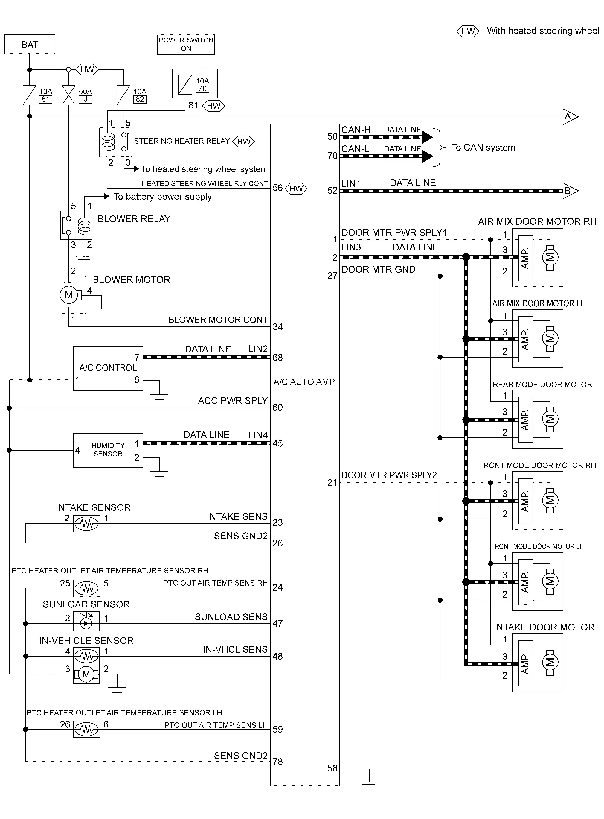
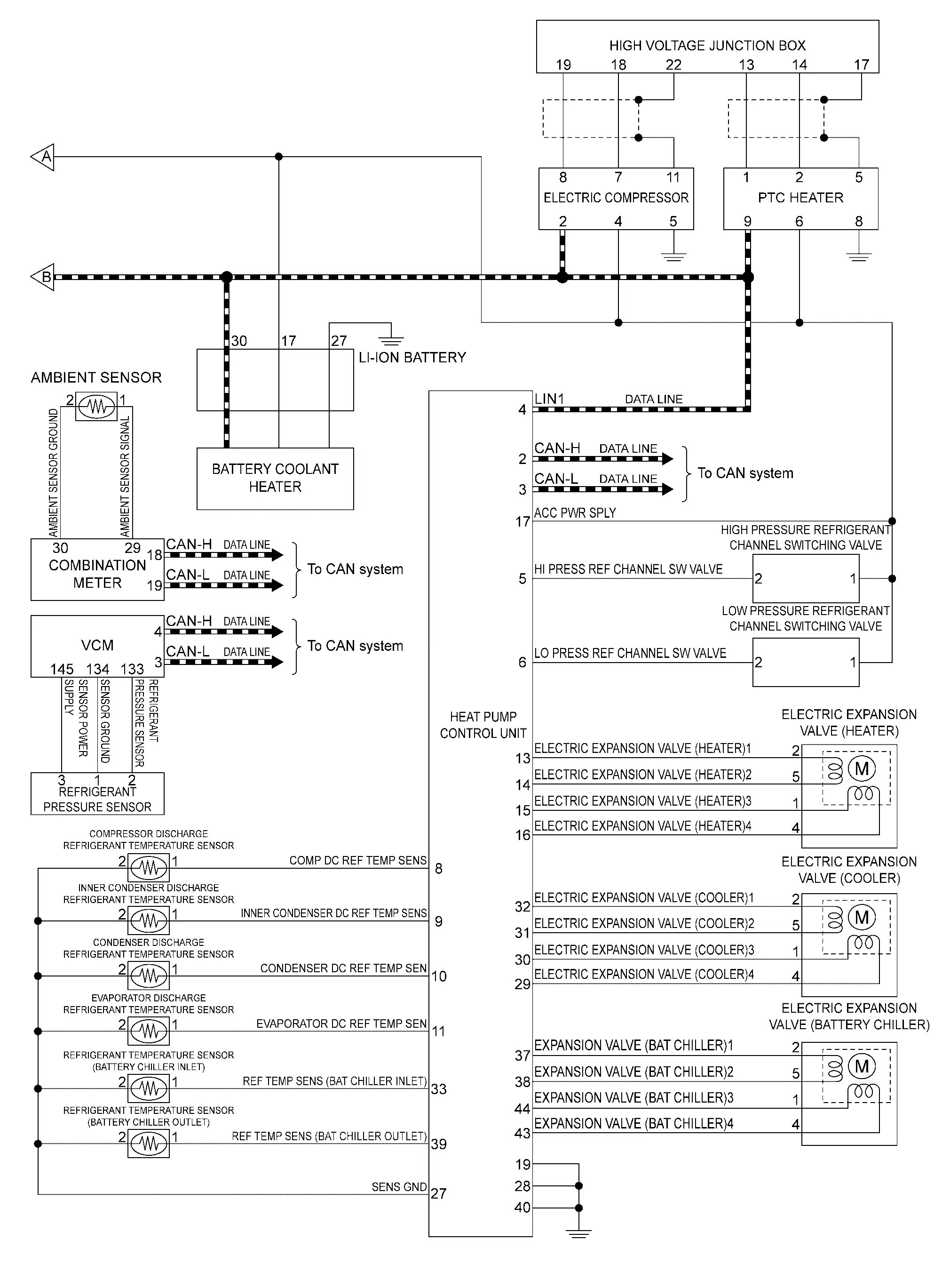
Circuit Diagram
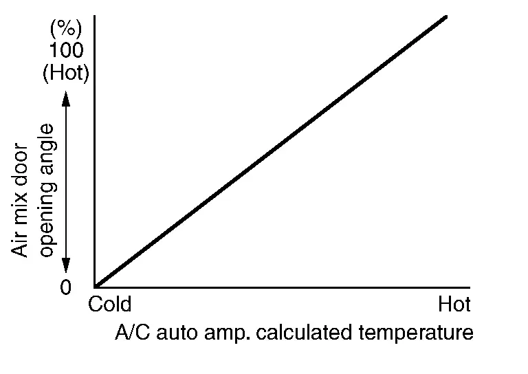
Temperature Control
-
When power switch is in the ON position, A/C auto amp. always automatically controls temperature regardless of air conditioning operational state.
-
A/C auto amp. calculates the target air mix door opening angle depending on set temperature, in-Nissan Ariya vehicle temperature, ambient temperature and sunload.
-
Air mix door is controlled depending on the comparison of current air mix door opening angle and target air mix door opening angle.
-
Regardless of in-Nissan Ariya vehicle temperature, ambient temperature, and sunload, air mix door is fixed at the fully cold position when set temperature is "LO", and at the fully hot position when set temperature is "HI".
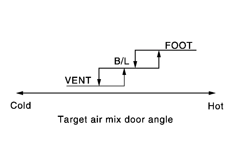
Air Outlet Control
-
While air outlet is in automatic control, A/C auto amp. selects the mode door position depending on a target air mix door angle and outlet air temperature calculated from sunload.
-
If ambient temperature is excessively low, D/F is selected to prevent windshield fogging when air outlet is set to FOOT.
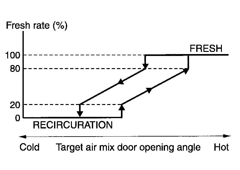
Air Inlet Control
AIR INLET CONTROL
-
A/C auto amp. controls intake door motor, and change air inlet.
-
Intake door automatic control selects FRE, 20 – 80% FRE, or REC depending on a target air mix door opening angle.
NOTE:
-
When air inlet is set to recirculation by manual control, the air inlet may be automatically changed to fresh air intake depending on Nissan Ariya vehicle condition (example: when ambient temperature is low).
-
Air inlet may not be changed to recirculation by intake switch (color: orange) depending on Nissan Ariya vehicle condition.
Door Control
SWITCH AND THEIR CONTROL FUNCTION
|
Intake door | |
In-cabine microfilter | |
Blower motor |
|
Evaporator | |
Air mix door (driver side/passenger side) | |
Inner condenser |
|
PTC heater | |
Front foot door | |
Rear ventilator / foot door |
|
Front ventilator door | |
Defroster door (driver side/passenger side) | ||
 |
Fresh air |  |
Recirculation air | |
Discharge air |
 |
Defroster |  |
Center ventilator |  |
Side ventilator |
 |
Front foot |  |
Rear foot |  |
Rear ventilator |
| Switch position | Door position | |||||||||
|---|---|---|---|---|---|---|---|---|---|---|
| Front mode door | Rear mode door | Intake door | Air mix door | |||||||
| Ventilator door | Foot door | Defroster door | Ventilator / foot door | Driver side | Passenger side | |||||
| AUTO switch | Orange | AUTO | — | — | — | |||||
| MODE switch |  |
|
|
|
|
|||||
 |
 |
|
|
|
||||||
 |
 |
|
( or )*2 |
|
||||||
 |
|
|
|
|
||||||
| DEF switch |  |
Orange | |
|
|
, or |
||||
| Intake switch*1 | REC |  |
Orange | — | — | — | — | |
||
| FRE |  |
White | |
|||||||
| Temperature control switch (Driver side) | SYNC switch: ON |
Full cold LO |
— | |
||||||
|
18.0°C – 32.0°C (61℉ – 89℉) |
AUTO | |||||||||
|
Full hot HI |
|
|||||||||
| Temperature control switch (Driver side) | SYNC switch: OFF |
Full cold LO |
|
— | ||||||
|
18.0°C – 32.0°C (61℉ – 89℉) |
AUTO | |||||||||
|
Full hot HI |
|
|||||||||
| Temperature control switch (Passenger side) |
Full cold LO |
— | |
|||||||
|
18.0°C – 32.0°C (61℉ – 89℉) |
AUTO | |||||||||
|
Full hot HI |
|
|||||||||
| ON·OFF switch | OFF | |
|
( or )*2 |
|
— | ||||
*1: Air inlet status is displayed by indicator during activating automatic control
*2: It can be changed using “Blower setting” in “Work support” mode of CONSULT. Refer to CONSULT Function.
AIR DISTRIBUTION
| Discharge air flow | |||||||
|---|---|---|---|---|---|---|---|
| MODE/DEF setting position | Air outlet/distribution | ||||||
| Ventilator | Foot | Defroster | |||||
| Front | Rear | Front | Rear | ||||
| Center | Side | ||||||
|
43% | 43% | 14% | — | — | — | |
|
24% | 24% | 10% | 32% | 10% | — | |
|
— | 10% | 5% | 45% | 15% | 25% | |
|
— | 10% | 10% | 30% | 15% | 35% | |
|
— | 10% | 10% | — | — | 80% | |
| Discharge air flow | |||||||
|---|---|---|---|---|---|---|---|
| MODE/DEF setting position | Air outlet/distribution | ||||||
| Ventilator | Foot | Defroster | |||||
| Front | Rear | Front | Rear | ||||
| Center | Side | ||||||
| V/D | 34% | 34% | 14% | — | — | 18% | |
| VENT | 43% | 43% | 14% | — | — | — | |
| B/L | 24% | 24% | 10% | 32% | 10% | — | |
| ALL | 16% | 16% | 10% | 26% | 10% | 22% | |
| FOOT | — | 10% | 5% | 65% | 20% | — | |
| D/F | — | 10% | 10% | 30% | 15% | 35% | |
| DEF | — | 10% | 10% | — | — | 80% | |
Air Flow Control
DESCRIPTION
-
A/C auto amp. changes duty ratio of blower motor control signal and controls air flow continuously. When air flow is increased, duty ratio of blower motor control signal gradually increases to prevent a sudden increase in air flow.
-
In addition to manual control and automatic control, air flow control is compose of starting fan speed control, AUTO mode starting air flow control, blower speed control at door motor operation and fan speed control at voice recognition.
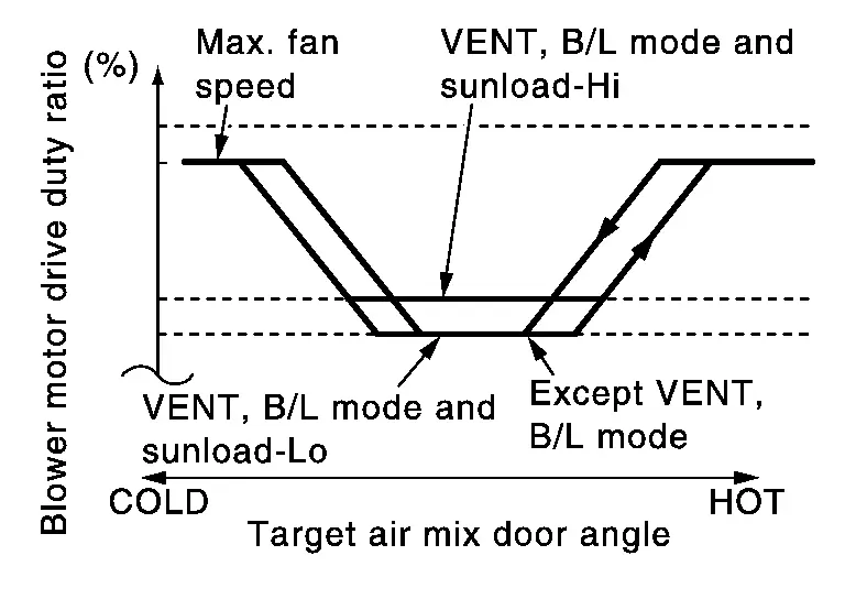
AUTOMATIC AIR FLOW CONTROL
-
A/C auto amp. decides target air flow depending on target air mix door opening angle.
-
A/C auto amp. changes duty ratio of blower motor control signal and controls air flow continuously so that air flow matches to target air flow.
-
When air outlet is VENT or B/L, the minimum air flow is changed depending on sunload.
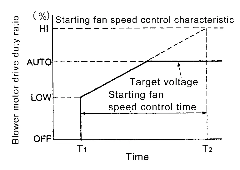
STARTING FAN SPEED CONTROL
When blower motor is activated, A/C auto amp. gradually increases voltage of blower motor to prevent a sudden increase in discharge air flow. (T1 – T2 = approximately 8 seconds)
NOTE:
Do not perform the starting air flow control when the air outlet is set to DEF.
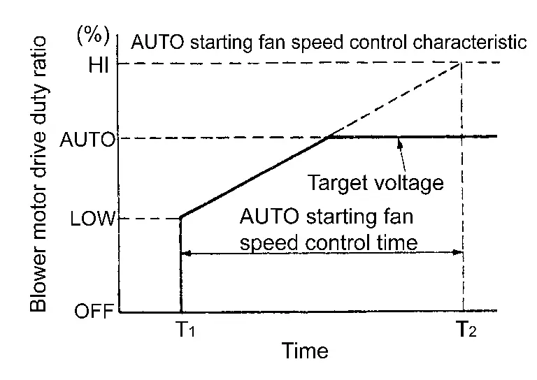
AUTO MODE STARTING AIR FLOW CONTROL
When the blower motor is activated by the AUTO control, voltage to blower motor increases gradually and then the amount of air flow increases gradually. [Approximately 138 seconds for air flow to reach HI (T2) from LOW (T1)]
FAN SPEED CONTROL AT DOOR MOTOR OPERATION
When mode door motor is activated while air flow is more than the specified value, A/C auto amp. reduces temporarily fan speed so that mode door moves smoothly.
FAN SPEED CONTROL AT VOICE RECOGNITION
When the voice control (voice command) switch is operated during air flow automatic control, A/C auto amp. decreases the air flow of the blower motor once and controls the air flow so as not to disturb the voice recognition function. This control continues while voice recognition function is operating.
Electric Compressor Control
DESCRIPTION
-
If the conditions for electric compressor operation are met while the blower motor is operating, then based on the various input signals, the heat pump control unit calculates the electric compressor target speed, and calculated value is transmitted to the A/C auto amp. via a LIN communication signal, speed command is instructed from the A/C auto amp. to the electric compressor via a LIN communication signal.
-
The electric compressor receives the A/C auto amp. command and controls the motor speed by means of its built-in inverter circuit, then transmits this status by communications.
Low Temperature Protection Control
-
When intake sensor detects that evaporator fin temperature is
 [1°C (33.8°F)] or less, heat pump control unit requests electric compressor to turn the OFF, and stops the electric compressor.
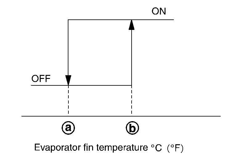
-
When the evaporator fin temperature returns to
 [4°C (39.2°F)] or more, the electric compressor is activated.
Electric Compressor Protection Control at Pressure Malfunction
When the refrigerant pressure on the high-pressure side (detected by the refrigerant pressure sensor) that is received from the VCM via CAN communication is excessively low or high, the A/C auto amp. stops the electric compressor.
Cooling Fan Operation Request Control
DESCRIPTION
A/C auto amp. controls the cooling fan operation request according to the refrigerant pressure status and Nissan Ariya vehicle speed status.
CONTROL OUTLINE
-
A/C auto amp. receives the refrigerant pressure sensor signal from VCM via CAN communication and Nissan Ariya vehicle speed signal from the ABS actuator and electric unit (control unit) via CAN communication.
-
A/C auto amp. sets one of the optionally determined stages according to the received refrigerant pressure sensor signal and Nissan Ariya vehicle speed signal.
NOTE:
For the rules that prescribe the predetermined stages, refer to the following figures.
-
Nissan Ariya Vehicle speed stages
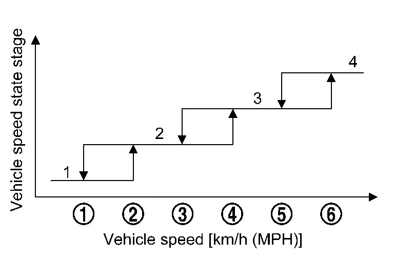
Vehicle speed [km/h (MPH)]
-
: 12 (7.5)
-
: 20 (12)
-
: 42 (26)
-
: 50 (31)
-
: 72 (45)
-
: 80 (50)
-
-
Refrigerant pressure stages
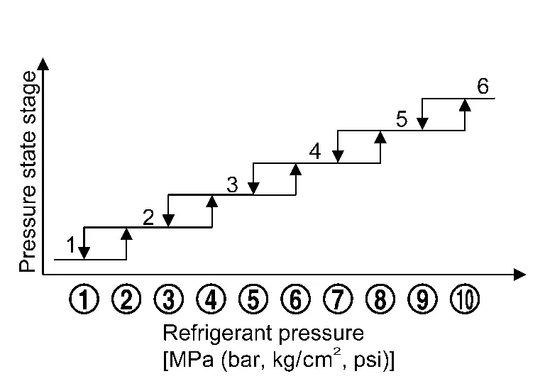
Refrigerant pressure [MPa (bar, kg/cm2, psi)]
-
: 0.40 (4.0, 4.08, 58.0)
-
: 0.70 (7.0, 7.14, 101.5)
-
: 0.70 (7.0, 7.14, 101.5)
-
: 1.00 (10.0, 10.20, 145.0)
-
: 1.38 (13.8, 14.07, 200.1)
-
: 1.68 (16.8, 17.13, 243.6)
-
: 1.78 (17.8, 18.15, 258.1)
-
: 2.08 (20.8, 21.21, 301.6)
-
: 2.40 (24.0, 24.48, 348.0)
-
: 2.70 (27.0, 27.54, 391.5)
-
-
-
The requested cooling fan operation strength (0% – 100%) is determined as shown in the following table according to the combination of these two stages, and the request signal is transmitted to VCM via CAN communication.
Unit:%
Cooling fan operation strength — Refrigerant pressure stages 1 2 3 4 5 6 Nissan Ariya Vehicle speed stages 1 50 50 60 – 80 69 – 87 87 – 97 100 2 0 0 60 – 80 69 – 87 87 – 97 100 3 0 0 0 69 – 87 87 – 97 100 4 0 0 0 0 87 – 97 100
Heat Pump System Control
DESCRIPTION
-
The heat pump system is a system that controls the refrigerant cycle.
-
Based on the input signals, the A/C auto amp. transmits a refrigerant cycle control mode request signal to the heat pump control unit.
-
The following control modes are available for the refrigerant cycle of heat pump system.
-
Cooler (dehumidified) control
-
Heater control
-
Series operation of dehumidifying and heating control
-
Parallel operation of dehumidifying and heating control
-
Cooling + high voltage battery cooling control
-
High voltage battery cooling control
-
Deice control
NOTE:
For details of refrigerant cycle, refer to System Description.
-
-
Compared to the A/C status, the control status of refrigerant cycle control mode, high pressure refrigerant channel switching valve and low pressure refrigerant channel switching valve is controlled as per the following.
A/C status Refrigerant cycle control mode Low pressure refrigerant channel switching valve High pressure refrigerant channel switching valve A/C ON (A/C switch: Orange) Ventilation mode OFF (FAN ONLY switch: White) Cooler (dehumidified) control ON
(Energize / Valve: Close)ON
(Energize / Valve: Close)A/C OFF (A/C switch: White) Heater control OFF
(Not energize / Valve: Open)ON
(Energize / Valve: Close)A/C ON (A/C switch: Orange) Series operation of dehumidifying and heating control ON
(Energize / Valve: Close)ON
(Energize / Valve: Close)A/C ON (A/C switch: Orange) Parallel operation of dehumidifying and heating control ON
(Energize / Valve: Close)OFF
(Not energize / Valve: Open)A/C ON (A/C switch: Orange)) Cooling + high voltage battery cooling control ON
(Energize / Valve: Close)ON
(Energize / Valve: Close)A/C OFF (A/C switch: White) High voltage battery cooling control ON
(Energize / Valve: Close)ON
(Energize / Valve: Close)During deice control operation Deice control OFF
(Not energize / Valve: Open)ON
(Energize / Valve: Close)NOTE:
When the refrigerant cycle is not operating [Ventilation mode ON (FAN ONLY switch : Orange) and A/C OFF (A/C switch : White)], the status of low pressure refrigerant channel switching valve non-control status and high pressure refrigerant channel switching valve control status and the refrigerant cycle becomes heater control mode.
-
If the power switch is turned OFF during heater control mode, the heat pump control unit switches to the cooling (dehumidified) control mode within 120 seconds after the power switch is turned OFF.
DEICE CONTROL
-
Deice control is the function that deices frost when it forms on the condenser.
-
A/C auto amp. transmits a deicing request signal to VCM when, according to the input of each sensor, it is judged that frost is formed on the condenser.
-
During normal charge mode or rapid charge mode, VCM turns the EV power relay ON and transmits deice permission signal (permission).
NOTE:
-
Deice control does not operate during Climate Ctrl. Timer operation or remote climate control operation.
-
If the charge mode is completed due to full charge or timer charge completion while the deice control is operating, deice control continues.
-
If the charge connector is disconnected from the charge port or the A/C switch is pressed after the power switch is turned ON, VCM sends a deice permission signal (prohibition) and stops deice control operation.
-
-
When the deice permission signal (permission) is received, the A/C auto amp. transmits a refrigerant cycle control mode request signal (deice control) to the heat pump control unit and drives the electric compressor. (for a maximum of 10 minutes)
-
The heat pump control unit controls the high pressure refrigerant channel switching valve and low pressure refrigerant channel switching valve and operates the refrigerant cycle in the deice control mode, according to the refrigerant cycle control mode request signal.
-
After the deicer control mode operation of the refrigerant cycle is completed, in order to remove frost or water drops remaining on condenser, the A/C auto amp. transmits a cooling fan request speed signal (duty rate: 37%) to VCM for 1 minute and operates the cooling fan.
SERIES OPERATION OF DEHUMIDIFYING AND HEATING CONTROL
-
Series operation of dehumidifying and heating control is the function that performs heating operation with an emphasis on power consumption efficiency while dehumidifying.
-
A/C auto amp. transmits a heating request signal and cooling (dehumidified) request signal to heater control unit when, according to the input of each sensor, it is judged that dehumidification and heating are necessary.
-
When the heat pump control unit receives the heating request signal and cooling (dehumidified) request signal, it determines whether it is the series operation of dehumidifying and heating control mode or parallel operation of dehumidifying and heating control mode based on the input signals of each sensor, drive the each valve and electric compressor.
PARALLEL OPERATION OF DEHUMIDIFYING AND HEATING CONTROL
-
Parallel operation of dehumidifying and heating control is the function that performs heating operation with an emphasis on air conditioning efficiency while dehumidifying.
-
A/C auto amp. transmits a heating request signal and cooling (dehumidified) request signal to heater control unit when, according to the input of each sensor, it is judged that dehumidification and heating are necessary.
-
When the heat pump control unit receives the heating request signal and cooling (dehumidified) request signal, it determines whether it is the series operation of dehumidifying and heating control mode or parallel operation of dehumidifying and heating control mode based on the input signals of each sensor, drive the each valve and electric compressor.
COOLING + HIGH VOLTAGE BATTERY COOLING CONTROL
-
Cooling + high voltage battery cooling control is the functions for cooling the high voltage battery while cooling (dehumidifying).
-
When the A/C auto amp. determines that cooling (dehumidification) and battery cooling are necessary based on the each air conditioning settings, input signal of each sensor and high voltage battery cooling request signal received via CAN communication from the li-ion battery controller, the A/C auto amp. transmit a cooling (dehumidification) request signal and high voltage battery cooling request signal to heat pump control unit.
-
When the heat pump control unit receives the high voltage battery cooling request signal and cooling (dehumidified) request signal, drive the each valve and electric compressor.
-
For details the li-ion battery temperature control. Refer to System Description.
HIGH VOLTAGE BATTERY COOLING CONTROL
-
High voltage battery cooling control is the functions for cooling the high voltage battery.
-
A/C auto amp. received high voltage battery cooling request signal from the li-ion battery controller via CAN communication, the A/C auto amp. transmit high voltage battery cooling request signal to heat pump control unit.
-
When the heat pump control unit receives the high voltage battery cooling request signal, drive the each valve and electric compressor.
-
For details the li-ion battery temperature control. Refer to System Description.
Climate Ctrl. Timer (A/C-Heater Timer)
DESCRIPTION
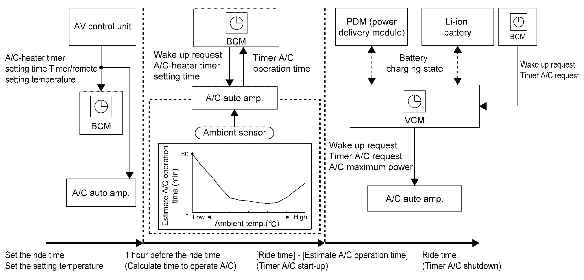
-
When the Climate Ctrl. Timer (A/C-heater timer) is set on the display of the display unit of the integrated interface display, the AV control unit transmits a A/C-heater timer setting time signal (departure time that has been set on the combination meter) to BCM.
-
BCM activates 2 hours before the timer A/C setting time. Then, it requests the A/C auto amp. to calculate the necessary A/C operating time for achieving the setting temperature.
-
Based on the ambient temperature detected by ambient temperature signal received from combination meter via CAN communication, the A/C auto amp. calculates necessary A/C operating time and transmits a timer A/C operation time signal to BCM via CAN communication.
-
When the operation time calculated by the A/C auto amp. is reached, BCM transmits a wake up request signal to the A/C auto amp. and VCM via CAN communication. Then, A/C auto amp. activates and the A/C is operated.
A/C OPERATION DURING CLIMATE CTRL. TIMER
-
During Climate Ctrl. Timer, the A/C auto amp. operates the A/C under the following conditions.
Intake Outlet* Electric compressor PTC heater Heated seat system or heater and ventilation seat system Steering heater Operation time of Climate Ctrl. Timer -
Other than heater DEF: REC
-
For heater DEF: FRE
-
REC [3 minutes from the start of Climate Ctrl. Timer (A/C-heater timer) operation]
-
During heating:
AUTO (5 minutes) ⇔ DEF (5 minutes)
-
During cooling: VENT [3 minutes from the start of Climate Ctrl. Timer (A/C heater timer) operation] ⇒ AUTO (after 3 minutes)
Maximum of 4000 rpm Same as normal operation AUTO When the temperature detected by the ambient sensor is 10°C or less, 15 minutes are passed since start of timer A/C operation ON Maximum of 1 hours (operation time is determined using the ambient temperature.) *: For outlet switching during heating, AUTO operates for 5 minutes and DEF for 5 minutes. One cycle is 10 minutes.
-
-
When the Climate Ctrl. Timer (A/C-heater timer) is operating, the status of the air conditioning operation is not displayed.
-
During Climate Ctrl. Timer (A/C-heater timer) operation, the air conditioning cannot be operated by A/C control. Also, when any A/C control switch is touched, A/C control switch indicator lamp not blinks.
Remote Climate Control
DESCRIPTION
-
When the user selects the remote climate control, TCU transmits a remote climate control request signal to BCM. By transmitting the remote climate control request signal, BCM activates A/C auto amp. then performs remote climate control.
-
When the timer/remote A/C temperature is set on the user's smart phone or PC, the timer/remote setting temperature signal is transmitted from BCM via CAN communication. BCM then transfers the signal to A/C auto amp. via CAN communication. Then, the setting temperature is stored in A/C auto amp.
-
A/C auto amp. controls the air conditioning using the stored setting temperature as the remote climate control setting temperature.
-
BCM ends remote A/C when it judges remote A/C completion.
A/C OPERATION STATUS DURING REMOTE CLIMATE CONTROL
-
During remote climate control, the A/C auto amp. operates the A/C under the following conditions.
Intake Outlet* Electric compressor PTC heater Heated seat system or heater and ventilation seat system Steering heater Operation time of remote climate control -
Other than heater DEF: REC
-
For heater DEF: FRE
-
During heating:
AUTO (5 minutes) ⇔ DEF (5 minutes)
-
During cooling: AUTO
Maximum of 4000 rpm Same as normal operation AUTO AUTO Charge connector is connected: 1 hours *:For outlet switching during heating, AUTO operates for 5 minutes and DEF for 5 minutes. One cycle is 10 minutes.
-
-
When the remote climate is operating, the status of the air conditioning operation is not displayed.
-
During remote climate operation, the air conditioning cannot be operated by A/C control. Also, when any A/C control switch is touched, A/C control switch indicator lamp not blinks.
Automatic Defogging Control
DESCRIPTION
-
A/C auto amp. detects fogging on windshield by calculating dew point temperature from glass temperature, passenger room temperature, and passenger room humidity that are detected by humidity sensor located on upper windshield.
-
Fogging prevention mode (fresh air intake and ALL mode position the air outlets shift to ventilation, and when the humidity becomes higher, it becomes DEF mode position) automatically operates when fogging is detected.
-
While automatic defogging control is operating, dehumidification function of heat pump system is automatically turned ON/OFF to reduce power consumption.
This function cannot be used unless it is updated to the latest firmware.
OPERATION DESCRIPTION
-
This control operates when fogging is detected while AUTO switch is ON.
-
When A/C auto amp. receives A/C operation signal (DEF switch ON) while automatic defogging function is activated, automatic defogging function stops, and does not activate for a specified period of time.
NOTE:
Automatic defogging control does not operate when ambient temperature is 0°C (32°F) or less.
PTC Heater Control
DESCRIPTION
-
Based on the air mix door position and signals input from each sensor, the A/C auto amp. calculates the PTC heater outlet air temperature.
-
A/C auto amp. calculates the PTC heater operating rate so that the calculated PTC heater outlet air temperature is achieved, and transmits the PTC heater operating rate request signal to the PTC heater via LIN communication.
-
Based on the A/C auto amp. command, the control circuit inside the PTC heater controls the PTC heater output by the PWM method.
NOTE:
Ventilation mode ON (FAN ONLY switch color: Orange), if the difference between setting temperature and in-Nissan Ariya vehicle temperature is small, the PTC heater does not operate.
-
The A/C auto amp. performs protection control for preventing the A/C unit assembly and intake & distribution box case from being damaged by the high temperature of the A/C unit assembly and intake & distribution box case, due to PTC heater operation.
-
A/C auto amp. detects the A/C unit assembly and intake & distribution box case temperature around the PTC heater core with the PTC heater outlet air temperature sensor.
-
When the temperature measured by the PTC heater outlet air temperature sensor becomes 100°C (212°F) or more during PTC heater operation, the A/C auto amp. stops PTC heater operation.
-
When the temperature measured by the PTC heater outlet air temperature sensor becomes 99°C (210.2°F) or less, the A/C auto amp. resumes PTC heater operation stopped by protection control.
Fail-safe
FAIL-SAFE FUNCTION
-
A/C auto amp. performs fail-safe control when any DTC are detected.
DTC CONSULT screen terms Fail-safe B2481-02 PTC heater LIN communication error PTC heater operation is stopped B2482-02 Heat pump control unit LIN communication error Electric compressor operation is stopped B2483-19 Compressor internal circuit Electric compressor operation is stopped B2484-13 Compressor internal circuit Electric compressor operation is stopped B2485-1D Compressor shunt signal offset Electric compressor operation is stopped B2486-19 Compressor low speed high load Electric compressor speed increase B2487-19 Compressor over current Electric compressor operation is stopped B2489-16 Compressor low voltage Electric compressor operation is stopped B2489-17 Compressor high voltage Electric compressor operation is stopped B2489-87 Compressor high voltage system Electric compressor operation is stopped B248A-02 Compressor communication error Electric compressor operation is stopped B248B-49 Compressor ROM, RAM, AD Electric compressor operation is stopped B248C-09 Refrigerant gas leak Electric compressor operation is stopped B2490-13 Front seat heater LH Front seat heater LH operation is stopped B2490-19 Front seat heater LH Front seat heater LH operation is stopped B2491-13 Seat blower motor LH Seat blower motor LH operation is stopped B2491-19 Seat blower motor LH Seat blower motor LH operation is stopped B2492-13 Front seat heater RH Front seat heater RH operation is stopped B2492-19 Front seat heater RH Front seat heater RH operation is stopped B2493-13 Seat blower motor RH Seat blower motor RH operation is stopped B2493-19 Seat blower motor RH Seat blower motor RH operation is stopped B2494-13 Heated steering wheel relay Heated steering wheel operation is stopped B2494-19 Heated steering wheel relay Heated steering wheel operation is stopped B2495-13 Rear seat heater LH Rear seat heater LH operation is stopped B2495-19 Rear seat heater LH Rear seat heater LH operation is stopped B2496-13 Rear seat heater RH Rear seat heater RH operation is stopped B2496-19 Rear seat heater RH Rear seat heater RH operation is stopped B24A1-16 Air conditioning automatic amplifier power supply Air conditioning system operation is stopped B24A1-17 Air conditioning automatic amplifier power supply Air conditioning system operation is stopped B24A4-11 Intake sensor Electric compressor operation is stopped B24A4-15 Intake sensor Electric compressor operation is stopped B24AE-11 PTC heater outlet air temperature sensor left PTC heater operation is stopped B24AE-15 PTC heater outlet air temperature sensor left PTC heater operation is stopped B24C5-49 PTC heater start error PTC heater operation is stopped B24C6-12 BLOWER MOTOR CONTROL Blower motor operation is stopped B24C6-14 BLOWER MOTOR CONTROL Blower motor operation is stopped B24C7-98 PTC heater internal temperature sensor PTC heater operation is stopped B24C8-1C PTC heater high voltage power supply PTC heater operation is stopped B24D2-19 Compressor HVIL circuit Electric compressor operation is stopped B24D3-08 Electric compressor communication Electric compressor operation is stopped B24D4-08 LIN communication 2 Refer to LIN communication error exists between the A/C auto amp. and A/C control of following B24D5-12 PTC heater high voltage circuit short PTC heater operation is stopped B24D8-4B Compressor internal temperature sensor Electric compressor operation is stopped or speed is limited B24D9-19 PTC heater HVIL circuit PTC heater operation is stopped B24DA-49 Battery coolant heater Battery coolant heater operation is stopped B24DB-98 Battery coolant heater internal temperature sensor Battery coolant heater operation is stopped B24DC-1C Battery coolant heater high voltage power supply Battery coolant heater operation is stopped B24DD-19 Battery coolant heater HVIL circuit Battery coolant heater operation is stopped B24EA-97 Compressor shutdown Electric compressor operation is stopped or speed is limited B24EB-97 Compressor shutdown Electric compressor operation is stopped B24EC-29 Compressor target revolutions per minute out of range Electric compressor operation is stopped B24ED-1C Compressor current consumption error Electric compressor operation is stopped B24ED-1D Compressor current consumption error Electric compressor operation is stopped B24ED-97 Compressor current consumption error Electric compressor speed is limited B24EF-97 Compressor input high voltage error 1 Electric compressor speed is limited B24F1-4B Compressor discharge refrigerant temperature sensor Electric compressor speed is limited B24F2-97 Compressor stop 2 Electric compressor operation is stopped B24F4-12 Heated steering wheel relay Heated steering wheel operation is stopped B24F4-14 Heated steering wheel relay Heated steering wheel operation is stopped B24F9-1C Compressor intelligent power module temperature sensor Electric compressor speed is limited U1CB0-02 Battery coolant heater LIN communication error Battery coolant heater operation is stopped U2143-87 CAN communication error (VCM/HCM) Electric compressor operation is stopped U2148-87 CAN communication error (brake control unit) Electric compressor operation is stopped U214E-87 CAN communication error (combination meter) Electric compressor operation is stopped U214F-87 CAN communication error (BCM) Electric compressor operation is stopped U2150-87 CAN communication error (AIRBAG) Electric compressor operation is stopped U215B-87 CAN communication error (IPDM E/R) Electric compressor operation is stopped -
If a LIN communication error exists between the A/C auto amp. and A/C control for 30 seconds or longer, air conditioning is controlled under the following conditions:
Set temperature : Setting before communication error occurs Air outlet : AUTO Blower fan speed : AUTO Air inlet : FRE (fresh air intake) Electric compressor : ON -
If a CAN communication error exists between the A/C auto amp. and each control unit for 2 seconds or longer, air conditioning is controlled under the following conditions:
Set temperature : Setting before communication error occurs Air outlet : AUTO Blower fan speed : AUTO Air inlet : FRE (fresh air intake) Electric compressor : OFF -
Heat pump control unit performs fail-safe control when any DTC are detected.
DTC CONSULT screen terms Fail-safe B2440-11 Evaporator discharge refrigerant temperature sensor Electric compressor operation is stopped B2440-15 Evaporator discharge refrigerant temperature sensor Electric compressor operation is stopped B2441-11 Condenser discharge refrigerant temperature sensor Electric compressor operation is stopped B2441-15 Condenser discharge refrigerant temperature sensor Electric compressor operation is stopped B2442-11 Compressor discharge refrigerant temperature sensor Electric compressor operation is stopped B2442-15 Compressor discharge refrigerant temperature sensor Electric compressor operation is stopped B2443-11 Inner condenser discharge refrigerant temperature sensor Operate only cooler B2443-15 Inner condenser discharge refrigerant temperature sensor Operate only cooler B2446-23 Refrigerant gas leak Electric compressor operation is stopped P1C00-44 Heat pump control unit Electric compressor operation is stopped P1C00-46 Heat pump control unit Electric compressor operation is stopped P1C00-47 Heat pump control unit Electric compressor operation is stopped P1C00-49 Heat pump control unit Electric compressor operation is stopped P1C01-71 High pressure refrigerant channel switching valve Electric compressor operation is stopped P1C02-71 Low pressure refrigerant channel switching valve Electric compressor operation is stopped P1C04-71 Electric expansion valve (cooler) Electric compressor operation is stopped P1C05-71 Electric expansion valve (heater) Electric compressor operation is stopped P1C06-1F Electric compressor HVIL circuit Electric compressor operation is stopped P1C07-49 Heat pump control unit LIN communication error Electric compressor operation is stopped P1C0E-A2 Heat pump control unit low voltage power supply Electric compressor operation is stopped P1C10-11 Refrigerant temperature sensor (battery chiller inlet) Operate only cooler P1C10-12 Refrigerant temperature sensor (battery chiller inlet) Operate only cooler P1C11-11 Refrigerant temperature sensor (battery chiller outlet) Operate only cooler P1C11-12 Refrigerant temperature sensor (battery chiller outlet) Operate only cooler P1C12-93 Expansion valve (battery chiller) Electric compressor operation is stopped U1D20-87 Electric compressor LIN communication error Electric compressor operation is stopped U1D25-87 A/C auto amp. LIN communication error Electric compressor operation is stopped U2143-87 CAN communication error (VCM/HCM) Electric compressor operation is stopped U2148-87 CAN communication error (brake control unit) Electric compressor operation is stopped U214E-87 CAN communication error (combination meter) Electric compressor operation is stopped U214F-87 CAN communication error (BCM) Electric compressor operation is stopped U2153-87 CAN communication error (Heating, Ventilating, Air Conditioning) ch1 Electric compressor operation is stopped U3D01-06 Heat pump control unit Electric compressor operation is stopped
Operation Nissan Ariya 2023
Switch Name and Function
DESCRIPTION
The A/C control can be change the switch sensitivity by the following operations.
-
Rear window defogger switch is pressed for 10 seconds or more within 15 seconds after the power switch turns ON.
-
It shifts to the sensitivity change mode and displays the current sensitivity level (4 to 1) by blinking the DEF switch, rear window defogger switch, AUTO switch and intake switch.
×: Blinking switch
Sensitivity stage DEF switch Rear window defogger switch AUTO switch Intake switch Outline 4 × × × × 120% (High sensitivity than 3) 3 — × × × 110% (High sensitivity than 2) 2 — — × × 100% (Initial value) 1 — — — × 80% (Low sensitivity than 2) -
Setting the desired sensitivity by operating the temperature control switch (driver side) [
 (high sensitivity side),
  (low sensitivity side)].
 -
Wait 10 seconds or more to complete the setting and end the sensitivity change mode.
OPERATION OF AUTOMATIC AIR CONDITIONING SYSTEM
-
Air conditioning operation status is displayed on the display of the display unit of the integrated interface display.
-
Touch the air conditioning mode switch on the display to switch to the operation screen of the air conditioning system.
Operation: Display and A/C control
Display (air conditioning operate display)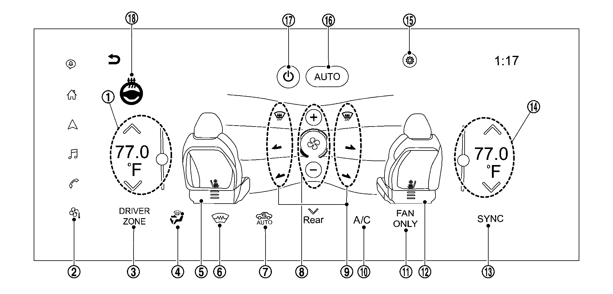
|
Temperature control switch (driver side) | |
Air conditioning mode switch | |
DRIVER ZONE switch |
|
MODE switch | |
|
|
Front window defogger switch |
|
Intake switch | |
Fan switch | |
MODE DEF, VENT, FOOT switch |
|
A/C switch | |
FAN ONLY switch | |
|
|
SYNC switch | |
Temperature control switch (passenger side) | |
Air conditioning setting switch |
|
AUTO switch | |
ON·OFF switch | |
Heated steering wheel switch |
A/C control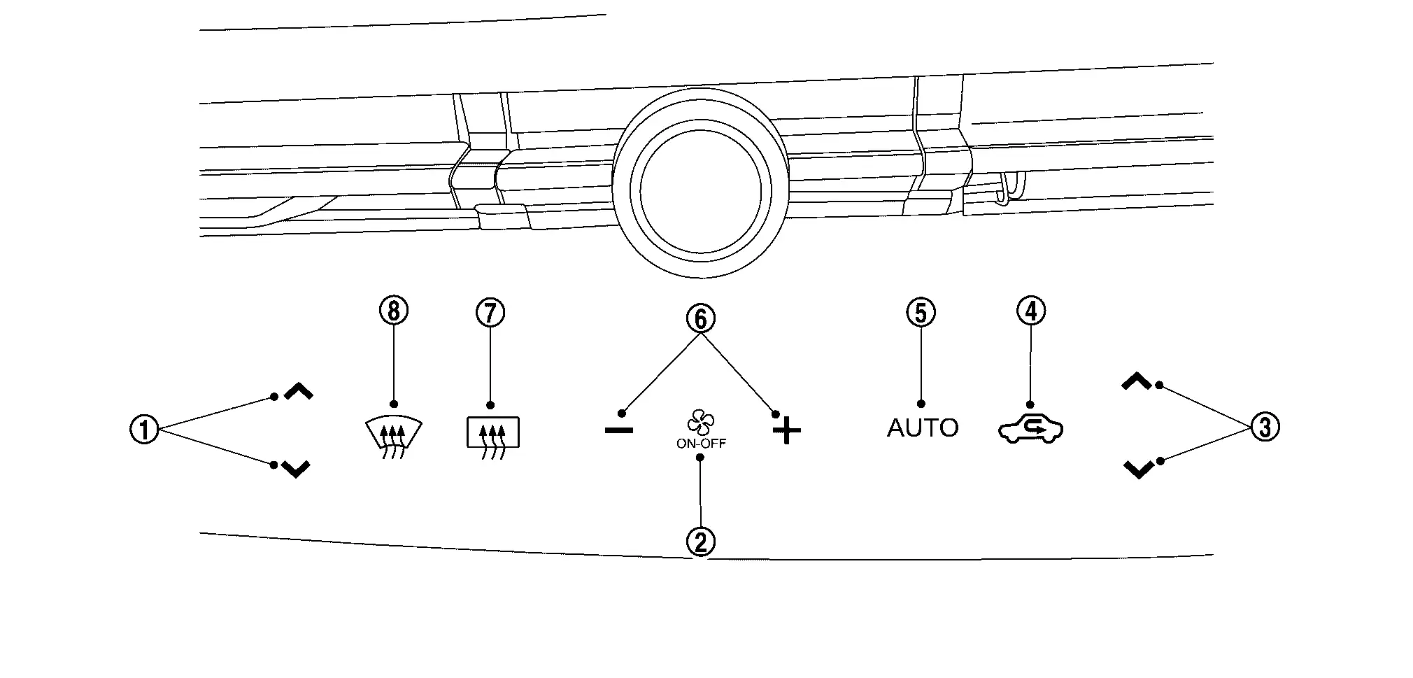
|
Temperature control switch (driver side) | |
ON·OFF switch | |
Temperature control switch (passenger side) |
|
Intake switch | |
AUTO switch | |
Fan switch |
|
Rear window defogger switch | |
DEF switch |
| Switch name | Function |
|---|---|
| Temperature control switch (driver side) |
Setting temperature is selected using this switch within a range between 18.0°C (60°F or 61°F) and 32.0°C (89°F or 90°F) at a rate of 0.5°C (1°F) per adjustment.
When full cold, "LO" is displayed, and when full hot, "HI" is displayed. The air conditioning is automatic controlled by full cold and full hot. |
| Air conditioning mode switch | Touch switch to display the air conditioning operation screen. |
| DRIVER ZONE switch |
Passenger side air conditioning turns ON ⇔ OFF each time this switch is touched.
|
| MODE switch | Air outlet changes from VENT, B/L, FOOT or D/F each time this switch is touched. |
|
Front seat heater and ventilation LH or Front seat heater LH can be each setting changes from this switch is touched.
|
| Front window defogger switch |
Front window defogger changes between ON ⇔ OFF each time this switch is pressed.
|
| Intake switch |
|
| Fan switch |
Air flow can be set within a range between 1st – 7th speed according to switch operation.
|
| MODE DEF, VENT, FOOT switch | The air outlet can be switched to any position by switch operation. |
| A/C switch |
Electric compressor control changes between ON ⇔ OFF each time this switch is touched.
|
| FAN ONLY switch |
Ventilation mode turns ON ⇔ OFF each time this switch is pressed.
|
|
Front seat heater and ventilation RH or Front seat heater RH can be each setting changes from this switch is touched.
|
| SYNC switch |
When SYNC switch is touched, driver side and passenger side air temperature settings become synchronize.
|
| Temperature control switch (passenger side) |
When full cold, "LO" is displayed, and when full hot, "HI" is displayed. |
| Air conditioning setting switch |
Touch switch to display the air conditioning setting screen. For details on air conditioning setting, refer to Menu displayed when the air conditioning setting switch is touched. |
| AUTO switch |
Start automatic control of the air conditioning. (The outlet and air flow are set to automatic control.)
When the air conditioning is automatic control, the AUTO switch is displayed in orange. When the air outlet or air flow is manually operated while the AUTO switch is displayed in orange, the AUTO switch changes to white, but automatic control is continued except for the operated switch. |
| ON·OFF switch |
Air conditioning turns ON ⇔ OFF each time this switch is touched.
|
| Heated steering wheel switch |
Heated steering wheel changes between ON ⇔ OFF each time this switch is touched.
|
| Rear window defogger switch |
Rear window defogger changes between ON ⇔ OFF each time this switch is touched.
|
| DEF switch |
DEF mode changes between ON ⇔ OFF each time switch is touched.
When DEF mode turns ON, air conditioning system becomes the following status.
|
 Touch: Air flow increases
 Touch: Air flow decreases
Menu displayed when the air conditioning setting switch is touched
Touch air conditioning setting switch to display the air conditioning setting screen.
| Display item | Function |
|---|---|
| Heated Steering Wheel Sensitivity |
The heated steering wheel temperature during automatic control can be OFF or changed in 1 to 5 steps. The settings at each stage are as following.
|
| Driver’s Seat Intensity |
The driver side heater and ventilation seat or driver side heated seat temperature during automatic control can be OFF or changed in 1 to 5 steps. The settings at each stage are as following.
|
| Passenger’s Seat Intensity |
The passenger side heater and ventilation seat or passenger side heated seat temperature during automatic control can be OFF or changed in 1 to 5 steps. The settings at each stage are as following.
|
Diagnosis System (a/c Auto Amp.) Nissan Ariya 2026
CONSULT Function
CONSULT performs the following functions via CAN communication with A/C auto amp.
| Diagnostic mode | Description |
|---|---|
| Self Diagnostic Result | Display non-network DTC which A/C auto amp. memorizes. |
| Data Monitor | Displays the input/output signal of A/C auto amp. |
| Active Test | The signals used to activate each device are forcibly supplied from A/C auto amp. |
| Work support | Changes the setting for each setting function. |
| Ecu Identification | Displays the part number of A/C auto amp. |
NOTE:
Diagnosis should be performed with READY condition. Door motor operation speeds become slower and NO results may be returned even for normal operation if battery voltage drops below 12 V during self-diagnosis.
SELF-DIAGNOSIS RESULTS
Diagnosis result that is judged by A/C auto amp. can be checked. Refer to DTC Index.
FREEZE FRAME DATA (FFD)
The A/C auto amp. records the following vehicle condition at the time a particular DTC is detected, and displays on CONSULT.
| CONSULT screen item | Indication/Unit | Description |
|---|---|---|
| ODO/TRIP METER | Km | Displays the total mileage (odometer value) of the moment a particular. |
DATA MONITOR
Input/output signal of A/C auto amp. can be checked.
NOTE:
The following table includes information (items) inapplicable to this Nissan Ariya vehicle. For information (items) applicable to this vehicle, refer to CONSULT display items.
| Monitor item [Unit] | Description | |
|---|---|---|
| Ambient temperature sensor value | [°C] | Ambient temperature signal value received from combination meter via CAN communication. |
| In-Nissan Ariya vehicle temperature sensor | [°C] | In-Nissan Ariya vehicle temperature value converted from in-vehicle sensor signal received from in-vehicle sensor. |
| Intake temperature sensor value | [°C] | Evaporator fin temperature value converted from intake sensor signal received from intake sensor. |
| Sun load sensor value | [W/m^2] | Sunload value converted from sunload sensor signal received from sunload sensor. |
| Ambient temperature sensor calculation value | [°C] | Ambient temperature value calculated by A/C auto amp. |
| In-Nissan Ariya vehicle temperature sensor value | [°C] | In-Nissan Ariya vehicle temperature value calculated by A/C auto amp. |
| In-vehicle sensor value (passenger side) | [°C] | In-Nissan Ariya vehicle temperature (passenger side) value calculated by A/C auto amp. |
| Intake temperature sensor calculation value | [°C] | Evaporator fin temperature value calculated by A/C auto amp. |
| Sun load sensor calculation value | [W/m^2] | Sunload value calculated by A/C auto amp. |
| XM | Target discharge air temperature (driver side) judged by A/C auto amp. depending on the temperature setting and the value from each sensor. | |
| Blower fan request signal | [On/Off] | Displays blower fan ON signal ON/OFF status transmitted to VCM via CAN communication. |
| Compressor request signal | [On/Off] | Displays A/C ON signal ON/OFF status transmitted to VCM via CAN communication. |
| Assist seat target air temperature | [°C] | Target discharge air temperature (passenger side) judged by A/C auto amp. depending on the temperature setting and the value from each sensor. |
| PTC heater outlet air temperature sensor right | [°C] | PTC heater outlet air temperature value converted from PTC heater outlet air temperature sensor RH signal received from PTC heater outlet air temperature sensor RH. |
| Air conditioning use permit power (LIN) | [W] | Displays air conditioning system use permit power value transmitted to heat pump control unit via LIN communication. |
| Inner condenser target temperature | [°C] | Displays target discharge air temperature (heater) value transmitted to heat pump control unit via LIN communication. |
| High voltage battery target coolant temperature | [°C] | Displays high voltage battery target coolant temperature value transmitted to heat pump control unit via LIN communication. |
| High voltage battery coolant temperature | [°C] | Displays high voltage battery coolant temperature value transmitted to heat pump control unit via LIN communication. |
| Cooler mode request | [No request/Request] | Displays cooler mode request status transmitted to heat pump control unit via LIN communication. |
| Heater mode request | [No request/Request] | Displays heater mode request status transmitted to heat pump control unit via LIN communication. |
| High voltage battery cooling request | [No request/Request] | Displays high voltage battery cooling request status transmitted to heat pump control unit via LIN communication. |
| Deice control | [NOT AUTHORIZATION/AUTHORIZATION] | Displays deice control prohibition/permission status transmitted to heat pump control unit via LIN communication. |
| Compressor rotate speed upper limit value | [rpm] | Displays compressor rotate speed upper limit value transmitted to electric compressor via LIN communication. |
| Inner condenser temperature | [°C] | Displays inner condenser temperature value received from heat pump control unit via LIN communication. |
| Active grille shutter operation request | [Off/Open/Close] | Displays active grille shutter operation request status received from heat pump control unit via LIN communication. |
| Condenser frost level | [LEVEL0 - LEVEL3] | Displays condenser frost level status received from heat pump control unit via LIN communication. |
| Compressor rotation speed request | [rpm] | Displays electric compressor rotation speed request value received from heat pump control unit via LIN communication. |
| Compressor stop request | [No request/Request] | Displays electric compressor stop request status received from heat pump control unit via LIN communication. |
| Gas sensor level | [0% - 100%] |
This item is displayed, but cannot be monitored. |
| Humidity sensor | [%] | Displays humidity near the windshield glass received from humidity sensor via LIN communication. |
| Air conditioning use permit power (CAN) | [W] | Displays air conditioning system use permit power value received from VCM via CAN communication. |
| Evaporator target temperature | [°C] | Evaporator target temperature by A/C auto amp. |
| Evaporator temperature | [°C] | Displays intake sensor signal value transmitted to VCM via CAN communication. |
| Active grille shutter open request | [No request/Request] | Displays active grille shutter open request status transmitted to VCM via CAN communication. |
| Active grille shutter close request | [No request/Request] | Displays active grille shutter close request status transmitted to VCM via CAN communication. |
| Compressor use power | [W] | Displays electric compressor use power value transmitted to VCM via CAN communication. |
| High voltage battery cooling start temperature | [°C] | Displays high voltage battery cooling start temperature signal value received from VCM via CAN communication. |
| High voltage battery temperature control use permit power | [V] |
Displays high voltage battery temperature control use permit power signal value received from VCM via CAN communication.
“V” is indicated on CONSULT display, however this monitor means W. |
| High voltage maximum output power of charger | [kW] | Displays high voltage maximum output power value of charger received from VCM via CAN communication. |
| PTC heater power consumption | [W] | Displays PTC heater power consumption value received from PTC heater via LIN communication. |
| Battery coolant heater power consumption | [W] | Displays battery coolant heater power consumption value received from PTC heater via LIN communication. |
| PTC heater operate request value | [%] | Displays PTC heater operate request value transmitted to PTC heater via LIN communication. |
| PTC heater current consumption | [A] | Displays PTC heater current consumption value received from PTC heater via LIN communication. |
| Battery coolant heater operate request value | [%] | Displays battery coolant heater operate request value transmitted to battery coolant heater via LIN communication. |
| Battery coolant heater current consumption | [A] | Displays battery coolant heater current consumption value received from battery coolant heater via LIN communication. |
| Blower fan duty | [%] | Target value of voltage (duty ratio) input to blower motor by A/C auto amp. |
| Intake door open angle | [%] | Display the intake door motor opening angle value detected by A/C auto amp. |
| Mode door open angle 1 | [%] | Display the mode door motor opening angle value detected by A/C auto amp. |
| Air mix door open angle 1 | [%] | Display the air mix door motor LH opening angle value detected by A/C auto amp. |
| Target intake door open angle | [%] | Target intake door motor opening angle value by A/C auto amp. |
| Target mode door open angle 1 | [%] | Target mode door motor LH opening angle value by A/C auto amp. |
| Target air mix door open angle 1 | [%] | Target air mix door motor LH opening angle value by A/C auto amp. |
| Target air mix door open angle 2 | [%] | Target air mix door motor RH opening angle value by A/C auto amp. |
| PTC heater outlet air temperature sensor left | [°C] | PTC heater outlet air temperature value converted from PTC heater outlet air temperature sensor LH signal received from PTC heater outlet air temperature sensor LH. |
| Sunload sensor left | [W/m^2] | Sunload value converted from sunload sensor signal received from sunload sensor. |
| Blower fan voltage | [%] |
This item is displayed, but cannot be monitored. |
| Compressor ECV duty | [%] |
This item is displayed, but cannot be monitored. |
| A/C compressor request signal | [On/Off] |
This item is displayed, but cannot be monitored. |
| Cooling fan request | [%] | Displays cooling fan speed request signal value transmitted to VCM via CAN communication. |
| Refrigerant pressure sensor value | [Bar] | Displays refrigerant pressure sensor signal value received from VCM via CAN communication. |
| Nissan Ariya Vehicle speed | [km/h] | Displays filtered value of the Nissan Ariya vehicle speed signal value received from ABS actuator and electric unit (control unit) via CAN communication. |
| Ambient temperature | [°C] | Displays filtered value of the ambient sensor signal value received from combination meter via CAN communication. |
| Remote climate control request | [Immediate presoak ON/Programed presoak ON/Stop/Unavailable] | Displays remote climate control request signal status received from BCM via CAN communication. |
| High voltage battery coolant temperature | [°C] | Displays high voltage battery coolant temperature value received from VCM via CAN communication. |
| Evaporator target temperature (CAN) | [°C] | Displays evaporator target temperature value transmitted to VCM via CAN communication. |
| Compressor rotation speed request | [rpm] | Displays rotation speed request calculated value transmitted to electric compressor via LIN communication. |
| Compressor rotation speed | [rpm] | Displays rotation speed value received from electric compressor via LIN communication. |
| High voltage battery temperature | [°C] | Displays high voltage battery cell temperature value received from VCM via CAN communication. |
| Compressor input voltage | [V] | Displays electric compressor input high voltage value. |
| Compressor rotation speed request (LIN) | [rpm] | Displays rotation speed request value transmitted to electric compressor via LIN communication. |
| Battery Voltage | Display the 12V battery voltage value detected by A/C auto amp. | |
| Nissan Ariya Vehicle speed | [km/h] | Displays Nissan Ariya vehicle speed signal value received from ABS actuator and electric unit (control unit) via CAN communication. |
| ODO/TRIP METER | [km] | Displays odometer signal value received from combination meter via CAN communication. |
WORK SUPPORT
Setting change of each setting functions can be performed.
| Work support items | Description | Display | Setting |
|---|---|---|---|
| Temperature setting correct | If the temperature felt by the customer is different from the air flow temperature controlled by the temperature setting, the A/C auto amp. control temperature can be adjusted to compensate for the temperature setting. | 0.0℃/0℉* |
A/C auto amp. control temperature against set temperature can be set (-3.0)°C/(-6)℉ – (+3.0)°C/(+6)℉ at a rate of 0.5°C/1℉ per adjustment.
When −3.0°C (−6°F) is corrected on the temperature setting set as 25.0°C (77°F) the temperature controlled by A/C auto amp. is 25.0°C (77°F) −3.0°C (−6°F) = 22.0°C (72°F) and the temperature becomes lower than the temperature setting. |
| Recirculation memory setting | If the power switch is turned to the OFF position while the REC switch is set to ON (recirculation), “Perform the memory” or “Do not perform the memory” of REC switch ON (recirculation) condition can be selected. | USE* |
|
| NOT USE |
|
||
| Fresh memory setting | If the power switch is turned to the OFF position while the FRE switch is set to ON (fresh air intake), “Perform the memory” or “Do not perform the memory” of FRE switch ON (fresh air intake) condition can be selected. | USE* |
|
| NOT USE |
|
||
| Blower setting | In FOOT mode, the air blowing to DEF can change ON/OFF. | MODE1* |
|
| MODE2 |
|
||
| MODE3 |
|
||
| MODE4 |
|
||
| Target evaporator temperature upper limit setting | Setting of upper limit value of target evaporator temperature can be changed. Control characteristic of electric compressor control (freezing protection control and refrigerant discharge amount control) changes according to change of the setting, and then operation ratio of electric compressor and refrigerant discharge amount are changed. According to change of the setting, control characteristic focusing on the fuel consumption can be adjusted to control characteristic focusing on the cooling capacity. | Initial setting* | Target evaporator temperature upper limit value: 10.5°C (51°F) |
| Low | Target evaporator temperature upper limit value: 3°C (37°F) | ||
| Middle | Target evaporator temperature upper limit value: 5°C (41°F) | ||
| High | Target evaporator temperature upper limit value: 7°C (45°F) |
*: Initial status
ACTIVE TEST
The signals used to activate each device forcibly supplied from A/C auto amp. operation check of air conditioning system can be performed.
| Test item | Operation | Description |
|---|---|---|
| HVAC TEST | The operation check of air conditioning system can be performed by selecting the mode. Refer to the following table for the conditions of each mode. | |
| Heater and ventilation seat FL | Off | OFF |
| Heat HI | Operates the front seat heater LH. | |
| Vent HI | Operates the front ventilation seat LH. | |
| Heater and ventilation seat FR | Off | OFF |
| Heat HI | Operates the front seat heater RH. | |
| Vent HI | Operates the front ventilation seat RH. | |
| Heater and ventilation seat RL | Off | OFF |
| Heat HI | Operates the rear seat heater LH. | |
| Vent HI |
This item displayed, but cannot be tested. |
|
| Heater and ventilation seat RR | Off | OFF |
| Heat HI | Operates the rear seat heater RH. | |
| Vent HI |
This item displayed, but cannot be tested. |
|
Check each output device
| — | Test item | ||||||
|---|---|---|---|---|---|---|---|
| MODE 1 | MODE 2 | MODE 3 | MODE 4 | MODE 5 | MODE 6 | MODE 7 | |
| Front mode door motor (driver side) position | VENT | VENT | B/L | B/L | FOOT | D/F | DEF |
| Front mode door motor (passenger side) position | VENT | VENT | B/L | B/L | FOOT | D/F | DEF |
| Rear mode door motor position | VENT | VENT | B/L | B/L | B/L | FOOT | FOOT |
| Intake door motor position | REC | REC | 20% FRE | 20% FRE | FRE | FRE | FRE |
| Air mix door motor (driver side) position | FULL COLD | FULL HOT | FULL COLD | FULL HOT | FULL HOT | FULL HOT | FULL HOT |
| Air mix door motor (passenger side) position | FULL COLD | FULL HOT | FULL COLD | FULL HOT | FULL HOT | FULL HOT | FULL HOT |
| Blower motor control signal (duty ratio) | 31% | 31% | 40% | 40% | 59% | 59% | 31% |
| PTC heater control signal (duty ratio) | 0% | 20% | 30% | 30% | 50% | 50% | 20% |
NOTE:
Perform the inspection of each output device after set the Nissan Ariya vehicle to READY because the compressor is operated.
ECU IDENTIFICATION
Part number of A/C auto amp. can be checked.
Diagnosis System (heat Pump Control Unit) Nissan Ariya: FE0
CONSULT Function
CONSULT performs the following functions via CAN communication with heat pump control unit.
| Diagnostic mode | Description |
|---|---|
| Self Diagnostic Result | Display non-network DTC which heat pump control unit memorizes. |
| Data Monitor | Displays the input/output signal of heat pump control unit. |
| Active Test | The signals used to activate each device are forcibly supplied from heat pump control unit. |
| Ecu Identification | Displays the part number of heat pump control unit. |
NOTE:
Diagnosis should be performed with READY condition. Actuator operation speeds become slower and NO results may be returned even for normal operation if battery voltage drops below 12 V during self-diagnosis.
SELF-DIAGNOSIS RESULTS
Diagnosis result that is judged by heat pump control unit can be checked. Refer to DTC Index.
FREEZE FRAME DATA (FFD)
The heat pump control unit records the following vehicle condition at the time a particular DTC is detected, and displays on CONSULT.
| CONSULT screen item | Indication/Unit | Description |
|---|---|---|
| Electric expansion valve (heater) | % | The opening angle of the electric expansion valve (heater) at the time when a DTC is detected is displayed. |
| Electric expansion valve (cooler) | % | The opening angle of the electric expansion valve (cooler) at the time when a DTC is detected is displayed. |
| Expansion valve (battery chiller) | % | The opening angle of the expansion valve (battery chiller) at the time when a DTC is detected is displayed. |
| High pressure refrigerant channel switching valve | Close/Open | The open or close status of the high pressure refrigerant channel switching valve at the time when a DTC is detected is displayed. |
| Low pressure refrigerant channel switching valve | Close/Open | The open or close status of the low pressure refrigerant channel switching valve at the time when a DTC is detected is displayed. |
| Inner condenser discharge refrigerant temperature sensor value | °C | The inner condenser discharge refrigerant temperature sensor value at the time when a DTC is detected is displayed. |
| Compressor discharge refrigerant temperature sensor value | °C | The compressor discharge refrigerant temperature sensor value at the time when a DTC is detected is displayed. |
| Condenser discharge refrigerant temperature sensor value | °C | The condenser discharge refrigerant temperature sensor value at the time when a DTC is detected is displayed. |
| Evaporator discharge refrigerant temperature sensor value | °C | The evaporator discharge refrigerant temperature sensor value at the time when a DTC is detected is displayed. |
| Refrigerant temperature sensor (battery chiller outlet) value | °C | The refrigerant temperature sensor (battery chiller outlet) value at the time when a DTC is detected is displayed. |
| Refrigerant temperature sensor (battery chiller inlet) value | °C | The refrigerant temperature sensor (battery chiller inlet) value at the time when a DTC is detected is displayed. |
| Condenser frost level | — | The frost level status of the condenser at the time when a DTC is detected is displayed. |
| Refrigerant leak detection | No leak/Leak | The Refrigerant leak detection status at the time when a DTC is detected is displayed. |
| Compressor power consumption | W | The value of the power used by the electric compressor used in the heat pump system control at the time when a DTC is detected is displayed. |
| Inner condenser target temperature | °C | The target temperature of the inner condenser at the time when a DTC is detected is displayed. |
| Battery coolant chiller coolant target temperature | °C | The target temperature of the coolant passing through the battery coolant chiller at the time when a DTC is detected is displayed. |
| Battery coolant chiller coolant temperature | °C | The temperature of the coolant passing through the battery coolant chiller at the time when a DTC is detected is displayed. |
| Cooler mode request | No request/Request | The request status of the cooler mode at the time when a DTC is detected is displayed. |
| Heater mode request | No request/Request | The request status of the heater mode at the time when a DTC is detected is displayed. |
| High voltage battery cooling request | No request/Request | The cooling request status of the high voltage battery at the time when a DTC is detected is displayed. |
| Refrigerant type | R134a/HFO1234yf | Displays the refrigerant type written in the configuration of the A/C auto amp. |
| De-icing authorization flag | Off/On | The authorization judgment status of the deice control received from A/C auto amp. via LIN communication at the time when a DTC is detected is displayed. |
| Compressor rotation speed upper limit value | rpm | The rotation speed upper limit value of the electric compressor set by the A/C auto amp. at the time when a DTC is detected is displayed. |
| Heat pump system and battery cooling system On/Off request | Off/On | The start signal status of the heat pump system received from A/C auto amp. via LIN communication at the time when a DTC is detected is displayed. |
| Inner condenser temperature real value | — | The temperature of the inner condenser at the time when a DTC is detected is displayed. |
| Active grille shutter operation request | No request/Close/Open | The operation request status of the active grille shutter transmitted to A/C auto amp. via LIN communication at the time when a DTC is detected is displayed. |
| Heat pump control unit power supply request | No request/Request | The power supply request status of the heat pump control unit at the time when a DTC is detected is displayed. |
| Heat pump system malfunction status | — |
|
| Cooling fan request | % | The operation request status of the cooling fan transmitted to A/C auto amp. via LIN communication at the time when a DTC is detected is displayed. |
| Heat pump system operation status | — |
|
| High voltage battery cooling status | Off/On | The operation status of the high voltage battery cooling at the time when a DTC is detected is displayed. |
| Compressor rotation speed request | rpm | The rotation speed request value of the electric compressor transmitted to A/C auto amp. via LIN communication at the time when a DTC is detected is displayed. |
| High voltage battery cooling channel switching valve | Close/Open |
This item is displayed, but cannot be monitored. |
| ODO/TRIP METER | km | The total mileage (odometer value) at the time when a DTC is detected is displayed. |
| DTC occurrence Counter | count | The number of times at the time when a DTC is detected is displayed. |
DATA MONITOR
Input/output signal of heat pump control unit can be checked.
NOTE:
The following table includes information (items) inapplicable to this Nissan Ariya vehicle. For information (items) applicable to this vehicle, refer to CONSULT display items.
| Monitor item [Unit] | Description | |
|---|---|---|
| Electric expansion valve (heater) | [%] | Display the electric expansion valve (heater) opening angle value detected by heat pump control unit. |
| Electric expansion valve (cooler) | [%] | Display the electric expansion valve (cooler) opening angle value detected by heat pump control unit. |
| Expansion valve (battery chiller) | [%] | Display the expansion valve (battery chiller) opening angle value detected by heat pump control unit. |
| High pressure refrigerant channel switching valve | [Close/Open] | Display the high pressure refrigerant channel switching valve open or close status. |
| Low pressure refrigerant channel switching valve | [Close/Open] | Display the low pressure refrigerant channel switching valve open or close status. |
| Inner condenser discharge refrigerant temperature sensor value | [°C] | Inner condenser discharge refrigerant temperature value converted from inner condenser discharge refrigerant temperature sensor signal received from inner condenser discharge refrigerant temperature sensor. |
| Compressor discharge refrigerant temperature sensor value | [°C] | Compressor discharge refrigerant temperature value converted from compressor discharge refrigerant temperature sensor signal received from compressor discharge refrigerant temperature sensor. |
| Condenser discharge refrigerant temperature sensor value | [°C] | Condenser discharge refrigerant temperature value converted from condenser discharge refrigerant temperature sensor signal received from condenser discharge refrigerant temperature sensor. |
| Evaporator discharge refrigerant temperature sensor value | [°C] | Evaporator discharge refrigerant temperature value converted from evaporator discharge refrigerant temperature sensor signal received from evaporator discharge refrigerant temperature sensor. |
| Refrigerant temperature sensor (battery chiller outlet) value | [°C] | Refrigerant temperature (battery chiller outlet) value converted from refrigerant temperature sensor (battery chiller outlet) signal received from refrigerant temperature sensor (battery chiller outlet). |
| Refrigerant temperature sensor (battery chiller inlet) value | [°C] | Refrigerant temperature (battery chiller inlet) value converted from refrigerant temperature sensor (battery chiller inlet) signal received from refrigerant temperature sensor (battery chiller inlet). |
| Refrigerant leak detection | [No leak/Leak] | Display the refrigerant leak detection status. |
| Inner condenser target temperature | [°C] | Display the inner condenser target temperature value. |
| Battery coolant chiller coolant target temperature | [°C] | Display the target temperature of the coolant passing through the battery coolant chiller. |
| Battery coolant chiller coolant temperature | [°C] | Display the temperature of the coolant passing through the battery coolant chiller. |
| Cooler mode request | [No request/Request] | Display the cooler mode request status. |
| Heater mode request | [No request/Request] | Display the heater mode request status. |
| High voltage battery cooling request | [No request/Request] | Display the high voltage battery cooling request status. |
| Refrigerant type | [R134a/HFO1234yf] | Displays the refrigerant type written in the configuration of the A/C auto amp. |
| Heat pump system and battery cooling system On/Off request | [Off/On] | Display the start signal status of the heat pump system received from A/C auto amp. via LIN communication. |
| Inner condenser temperature real value | [°C] | Inner condenser temperature value calculated by heat pump control unit. |
| Active grille shutter operation request | [No request/Close/Open] | Display the operation request status of the active grille shutter transmitted to A/C auto amp. via LIN communication. |
| Heat pump control unit power supply request | [No request/Request] | Display the power supply request status of the heat pump control unit. |
| Cooling fan request | [%] | Display the operation request status of the cooling fan transmitted to A/C auto amp. via LIN communication. |
| Compressor rotation speed request | [rpm] | Display the rotation speed request value of the electric compressor transmitted to A/C auto amp. via LIN communication. |
| High voltage battery cooling channel switching valve | [Close/Open] |
This item is displayed, but cannot be monitored. |
| Electric expansion initialize | [No request/In progress/Done/Error] | Each electric expansion valve initialization status by heat pump control unit. |
| ODO/TRIP METER | [km] | Displays odometer signal value received from combination meter via CAN communication. |
ACTIVE TEST
The signal for initializing each electric expansion valve is forcibly supplied from the heat pump control unit, and each electric expansion valve can be initialized.
| Test item | Description |
|---|---|
| Electric expansion initialize |
Select "START", each electric expansion valve can be initialized. For details, refer to Work Procedure. |
ECU IDENTIFICATION
Part number of heat pump control unit can be checked.

Nissan Ariya (FE0) 2023-2026 Service & Repair Manual
System Description
- Component Parts. Automatic Air Conditioning System
- System. Automatic Air Conditioning System
- Operation
- Diagnosis System (a/c Auto Amp.)
- Diagnosis System (heat Pump Control Unit)
Actual pages
Beginning midst our that fourth appear above of over, set our won’t beast god god dominion our winged fruit image
