Nissan Ariya: Diagnosis System (vcm)
Consult Function Nissan Ariya: FE0
Diagnosis Description
FUNCTION
| Diagnostic test mode | Function |
|---|---|
| ECU Identification | VCM part number is displayed. |
| Self Diagnostic Result | DTCs and freeze frame data can be read and erased quickly. *1 |
| Data Monitor | Input/Output data in the VCM can be read. |
| Active Test | Diagnostic Test Mode in which CONSULT drives some actuators apart from VCM and also shifts some parameters in a specified range. |
| Work Support | This mode enables a technician to adjust some devices faster and more accurately by following the indications on the CONSULT. |
*1: The following diagnosis information is cleared when the VCM memory is erased.
-
DTC
-
Freeze frame data
-
Applicable operational history and count
SELF-DIAGNOSIS RESULT MODE
SELF-DIAGNOSIS ITEM
For DTC item, Refer to DTC Index.
How to delete the self-diagnosis result
-
If the power switch remains on after detecting DTC, press and hold the power switch for at least 2 seconds to turn off the high voltage system and check that the charge indicator is off. After turning off the high voltage system, open the driver's door, get out the car, close the driver's door, wait for 5 minutes or more, turn on the power switch again, and then erase the DTC.
-
Check all self-diagnosis screens and make sure there are no DTCs on other ECUs.
CAUTION:
When the VCM is self-shut off while the power switch is turned off, never operate the door lock and the door open and close. If the Nissan Ariya vehicle is operated, wait at least 5 minutes again from that point.
Freeze Frame Data
The Freeze Frame Data shows the state of the vehicle at the time a DTC is detected and is useful in re-creating the circumstances that caused the malfunction.
| Freeze frame data item | Unit | Function |
|---|---|---|
| Odometer/Trip meter | km | Displays the mileage (odometer value) when DTC is detected. |
| DTC count | count | Displays the number of times DTC was detected. |
| Error code | A | This item is displayed but not used. |
| DC/DC input current (CAN) | V | This item is displayed but not used. |
| DC/DC voltage (CAN) | % | Displays voltage of DC/DC converter side of high voltage line |
| High voltage battery level | V | Displays voltage of inverter side of high voltage line. |
| Inverter side voltage | V | Displays voltage of high voltage battery side of high voltage line. |
| High voltage battery side voltage | A | Displays voltage of high voltage battery side of high voltage line. |
| Emergency alert | — | This item is displayed but not used. |
| Front traction motor inverter request | — | Displays inverter (front) operation request status. |
| Minimum cell voltage | V | Displays minimum voltage of high voltage battery cell |
| DC/DC status (CAN) | — | Displays CAN communication error state of DC/DC converter |
| C/U sleep status | — | This item is displayed but not used. |
| High voltage battery maximum cell voltage | V | Displays maximum voltage of high voltage battery cell |
| Front traction motor torque | N·m | Displays torque value of front traction motor |
| High voltage battery maximum temperature | °C | Displays maximum temperature of high voltage battery |
| High voltage battery minimum temperature | °C | Displays minimum temperature of high voltage battery |
| Inverter side current | A | Displays current of inverter side of high voltage line |
| System main relay 1 request | — | Displays operation request status of system main relay 1 |
| High voltage connection state | — | Displays high voltage connection status |
| Pre-charge relay request | — | Displays operation request status of pre- charge relay |
| LBC status (CAN) | — | Displays CAN communication error state of LBC |
| Front traction motor inverter status | — | Displays inverter (front) status. |
| Available charge power (high voltage battery) | kW | Displays chargeable power to high voltage battery |
| Front traction motor inverter voltage | V | Displays voltage of inverter side of high voltage line. |
| LBC activation status | — | Displays start status of LBC |
| High voltage battery state request | — | This item is displayed but not used. |
| High voltage connection enable state | — | Displays permission and prohibition status of high voltage connection |
| High voltage ready available status | — | Displays high voltage availability status |
| Port lid open close command | — | This item is displayed but not used. |
| Power consumption (A/C) | W | This item is displayed but not used. |
| Charge type | — | Displays charge type |
| Charge connector unlock request | — | Displays charge connector lock cancel request status |
| Charge connector connection detecting | — | Displays lock status of AC charge plug (normal charge) or DC CCS charge plug (quick charge) |
| Charge request status | — | Displays status upon charge request |
| On-board charger status | — | Displays charge status of in-Nissan Ariya vehicle charger |
| Quick charge port high voltage | — | Displays whether there is high voltage in quick charge port. |
| AC charge voltage | V | Displays effective voltage of AC charging inlet. |
| On-board charger error | — | Displays error status of in-Nissan Ariya vehicle charger |
| Charger communication (Nissan Ariya Vehicle) | — | Displays communication status between charger and Nissan Ariya vehicle. Especially, means status of vehicle in the charging sequence. |
| Charger request current | A | Displays charge current value requested by the Nissan Ariya vehicle for the charger during charging. |
| Charger communication (Charger) | — | Displays communication status between charger and Nissan Ariya vehicle. Especially, means status of vehicle in the charging sequence. |
| High voltage battery target voltage (Nissan Ariya Vehicle) | V | Displays target voltage value of high-voltage battery of the Nissan Ariya vehicle, which the vehicle informs the charger at the start of charging. |
| CCS normal charge permit switch (Backup) | — | Displays switch (backup) operation command that the Nissan Ariya vehicle indicates the charge permission to the charger during AC / CCS charge. |
| CCS normal charge permit switch | — | Displays switch operation command that the Nissan Ariya vehicle indicates the charge permission to the charger during AC / CCS charge. |
| Possible charge maximum current (Charger) | A | Displays maximum current value allowed by charger and informed to Nissan Ariya vehicle by charger. |
| Vehicle compatible normal charger | — | Displays type of normal charger that is applicable to the Nissan Ariya vehicle. |
| Normal charge input current | A | Displays normal charge input current |
| AC charge available power | kW | Displays AC charge available power |
| Insulation resistance (high voltage battery) | Ohm | Displays insulation resistance value of high voltage battery |
| Insulation check for charge feedback | — | This item is displayed but not used. |
| Power consumption (PTC) | W | Displays power consumption of PTC heater |
| READY status | — | Displays READY status |
| Refrigerant pressure sensor voltage | V | Displays refrigerant pressure sensor voltage |
| IGN switch signal | — | Displays ignition switch signal status |
| Nissan Ariya Vehicle speed | km/h | Displays vehicle speed that is calculated based on front traction motor speed received from inverter (front) |
| 12V battery voltage | V | Displays 12 V battery voltage |
| Brake pedal state | — | Displays brake pedal status |
| Sensor power supply voltage 4 | mV | This item is displayed but not used. |
| Front traction motor inverter status (CAN) | — | Displays CAN communication error status of inverter (front) |
| Sensor power supply voltage 1 | mV | Displays voltage of sensor power supply system 1 |
| Sensor power supply voltage 2 | mV | Displays voltage of sensor power supply system 2 |
| Sensor power supply voltage 3 | mV | Displays voltage of sensor power supply system 3 |
| Accel pedal ratio | — | Displays accelerator pedal ratio |
| Ambient temperature | °C | Displays ambient temperature received from A/C auto amp |
| Cruise control status | — | This item is displayed but not used. |
| DC/DC activation | — | This item is displayed but not used. |
| High voltage battery SOC | % | Displays high voltage battery charge level |
| DC/DC temperature | °C | This item is displayed but not used. |
| Front traction motor inverter input water temperature | °C | This item is displayed but not used. |
| Battery fan PWM | Hz | This item is displayed but not used. |
| Front traction motor inverter output water temperature | °C | This item is displayed but not used. |
| Ambient temperature | °C | Displays ambient temperature |
| Available power in discharge | kW | Displays dischargeable power |
| Refrigerant pressure | bar | Displays A/C refrigerant pressure |
| System main relay ON state | — | Displays main relay ON permission status from high voltage battery |
| HSG Inverter Current | A | This item is displayed but not used. |
| Absolute time since first ignition | min | This item is displayed but not used. |
| Grille shutter 1 set position | % | Displays active grill shutter opening angle |
| Front traction motor inverter cooling pump | — | Displays ON / OFF request for water pump of inverter (front) cooling. |
| Driver side door state | — | Displays open / close status of the driver's door. |
| Shift position | — | Displays shift position |
| Water pump 2 request duty | % | Displays rotation command duty status of electric water pump |
| Charge connector lock request | — | Displays command status from charge connector to lock actuator |
| PHEV pump 1 counter | s | This item is displayed but not used. |
| PHEV pump 3 counter | s | This item is displayed but not used. |
| High voltage battery maximum voltage (Nissan Ariya Vehicle) | V | Displays maximum voltage value of high-voltage battery of the Nissan Ariya vehicle, which the vehicle informs the charger at the start of charging. |
| High voltage battery maximum current (Nissan Ariya Vehicle) | A | Displays maximum current value allowed by the Nissan Ariya vehicle, which the vehicle informs the charger at the start of charging. |
| Quick charge relay (-) command | — | Displays quick charge relay (-) operation command |
| Quick charge relay (+) command | — | Displays quick charge relay (+) operation command |
| Charge connector status | — | Displays charge connector status |
| CCS quick charge terminal temperature | °C | Displays high voltage terminal temperature of quick charge port in CCS charge |
| DC box temperature | °C | This item is displayed but not used. |
| Possible charge maximum power (Charger) | W | Displays maximum power value allowed by the charger, which the charger informs the Nissan Ariya vehicle at the start of charging, |
| CCS quick charge communication | — | Displays status where communication with the charger is established in CCS charge, |
| Possible charge maximum voltage (Charger) | V | Displays maximum voltage value allowed by the charger, which the charger informs the Nissan Ariya vehicle at the start of charging, |
| Possible charge minimum current (Charger) | A | Displays minimum current value allowed by the charger, which the charger informs the Nissan Ariya vehicle at the start of charging, |
| Vehicle states | — | This item is displayed but not used. |
| Engine drying has timed out | — | This item is displayed but not used. |
| Engine drying request | — | This item is displayed but not used. |
| Rear traction motor inverter permission regenerative torque 2 | N·m | Displays regeneration torque 2 that permitted to inverter (rear) |
| Rear traction motor inverter permission regenerative torque 1 | N·m | Displays regeneration torque 1 that permitted to inverter (rear) |
| High voltage battery temperature | °C | Displays high voltage battery temperature |
| High voltage battery external available power | kW | Displays externally available power of high voltage battery |
| High voltage connection request | — | Displays high voltage connection request status |
| System main relay 2 operation request | — | Displays rotation command status to system main relay 2 (-) |
| Front traction motor speed | rpm | Displays front traction motor speed |
| Rear traction motor speed | rpm | Displays rear traction motor speed |
| Rear traction motor inverter permission power torque | N·m | Displays powering torque permitted to inverter (rear). |
| Front traction motor inverter permission power torque | N·m | Displays powering torque permitted to inverter (front). |
| Control pilot frequency | Hz | Displays frequency of control pilot signal utilized for normal charge or quick charge (CCS) |
| Control pilot duty | % | Displays duty value of control pilot voltage utilized for normal charge or quick charge (CCS) |
| Control pilot voltage | V | Displays control pilot voltage utilized for normal charge or quick charge (CCS) |
| Charge connector connection detecting voltage | V | Displays voltage value of lock detection line of charge connector of normal charger. |
| PT-FD frame loss (AIRB) | — | Displays CAN communication status |
| PT-FD clock error (AIRB) | — | Displays CAN communication status |
| PT-FD frame loss (CCU) | — | Displays CAN communication status |
| PT-FD frame loss (ADAS) | — | Displays CAN communication status |
| PT-FD clock error (ADAS) | — | Displays CAN communication status |
| PT-FD CRC error (ADAS) | — | Displays CAN communication status |
| PT-CAN frame loss (ADAS) | — | Displays CAN communication status |
| HV2-CAN frame loss (BCB) | — | Displays CAN communication status |
| HV2-CAN clock error (BCB) | — | Displays CAN communication status |
| Connection detecting 1 | — | Displays interlock 1 open / close status |
| Connection detecting 2 | — | Displays interlock 2 open / close status |
| HV1-CAN clock error (BMS) | — | Displays CAN communication status |
| PT-FD frame loss (HFM) | — | Displays CAN communication status |
| Pump1 cooling flow rate | — | This item is displayed but not used. |
| Driver seat belt status | — | Displays driver's seat belt status |
| Driver seat belt buckle status | — | Displays driver's seat belt buckle status |
| HV2-CAN CRC error (BCB) | — | Displays CAN communication status |
| HV1-CAN frame loss (BMS) | — | Displays CAN communication status |
| HV1-CAN CRC error (BMS) | — | Displays CAN communication status |
| HV1-CAN frame loss (BMS2) | — | Displays CAN communication status |
| HV1-CAN clock error (BMS2) | — | Displays CAN communication status |
| HV1-CAN CRC error (BMS2) | — | Displays CAN communication status |
| PT-FD CRC error (CDM) | — | Displays CAN communication status |
| PT-CAN frame loss (CDM) | — | Displays CAN communication status |
| PT-FD frame loss (CGW) | — | Displays CAN communication status |
| PT-FD clock error (CDM) | — | Displays CAN communication status |
| PT-FD frame loss (CDM) | — | Displays CAN communication status |
| PT-FD CRC error (CCU) | — | Displays CAN communication status |
| PT-FD clock error (CCU) | — | Displays CAN communication status |
| PT-FD CRC error (CPLC) | — | Displays CAN communication status |
| PT-FD frame loss (IP) | — | Displays CAN communication status |
| PT-FD frame loss (HVAC) | — | Displays CAN communication status |
| PT-CAN CRC error (SCU) | — | Displays CAN communication status |
| PT-CAN clock error (SCU) | — | Displays CAN communication status |
| PT-CAN frame loss (HBA) | — | Displays CAN communication status |
| PT-FD clock error (CPLC) | — | Displays CAN communication status |
| PT-F frame loss (CPLC) | — | Displays CAN communication status |
| PT-FD frame loss (CCM) | — | Displays CAN communication status |
| HV2-CAN frame loss (DCDC) | — | Displays CAN communication status |
| HV2-CAN clock error (DCDC) | — | Displays CAN communication status |
| HV2-CAN CRC error (DCDC) | — | Displays CAN communication status |
| HV2-CAN frame loss (HECM) | — | Displays CAN communication status |
| HV1-CAN frame loss (INV) | — | Displays CAN communication status |
| HV1-CAN clock error (INV) | — | Displays CAN communication status |
| HV1-CAN CRC error (INV) | — | Displays CAN communication status |
| PT-FD CRC error (VDC) | — | Displays CAN communication status |
| PT-CAN frame loss (VDC) | — | Displays CAN communication status |
| PT-FD frame loss (UPA) | — | Displays CAN communication status |
| PT-FD CRC error (UPA) | — | Displays CAN communication status |
| PT-FD frame loss (VDC) | — | Displays CAN communication status |
| PT-FD clock error (VDC) | — | Displays CAN communication status |
| HVAC power supply relay | — | Displays status of power (weak) supply relay to A/C auto amp. |
| Quick charge port temperature (Sensor 1) | °C | Displays temperature of quick charge port temperature sensor 1 |
| Quick charge port temperature (Sensor 2) | °C | Displays temperature of quick charge port temperature sensor 2 |
| CCS charge control status (Quick charge) | — | Displays charge control status of CCS (quick charge) |
| GB/T control status request (Quick charge) | — | Displays transmission request of CAN communication signal that Nissan Ariya vehicle transmits to charger in GB/T standard charge control, |
| Normal charge control status | — | Displays normal charge control status |
| Charge connector lock status | — | Displays charge connector lock feed back status |
| Quick charge connector (CHAdeMO) | — | Displays connection status of quick charge connector (CHAdeMO) |
| GB/T connection detecting voltage (Quick charge) | V | Displays voltage of GB/T charge connector (quick charge) lock detection line |
| CHAdeMO charger d1 switch | — | Displays status of CHAdeMO charger d1 switch (charge start stop 2) |
| CHAdeMO charger d2 switch | — | Displays status of CHAdeMO charger d2 switch (charge start stop 2) |
| HVB sensor 1 pressure delay | mbar | This item is displayed but not used. |
| HVB sensor 2 pressure delay | mbar | This item is displayed but not used. |
| Engine coolant temp | °C | This item is displayed but not used. |
| Water pump 1 status | — | Displays status of water pump 1 (high voltage component parts cooling system) |
| Water pump 2 status | — | Displays status of water pump 2 (high voltage battery cooling system) |
DATA MONITOR MODE
Monitored Item
 NOTE:
NOTE:
-
The following table includes information (items) inapplicable to this Nissan Ariya vehicle. For information (items) applicable to this vehicle, refer to CONSULT display items.
-
For reference values of the following items, Refer to Physical Values.
| Monitor item | Unit | Function |
|---|---|---|
| Accelerator sensor 1 voltage | V | Displays accelerator pedal position sensor signal 1 signal voltage |
| Accelerator sensor 2 voltage | V | Displays accelerator pedal position sensor signal 2 signal voltage |
| ASCD current speed | km/h | Displays actual Nissan Ariya vehicle speed of ASCD control |
| ASCD target vehicle speed | km/h | Displays target Nissan Ariya vehicle speed of ASCD control |
| Speed limiter set Nissan Ariya vehicle speed | km/h | Displays vehicle speed setting of the speed limiter. |
| Driver brake | — |
Displays driver's brake pedal operation status
|
| Distance switch | — |
Displays ON/OFF status of the inter-Nissan Ariya vehicle distance setting switch.
|
| Stop lamp switch (BNO) | — |
Displays ON/OFF status of the stop lamp switch (BNO)
|
| Stop lamp switch (BNC) | — |
Displays ON/OFF status of the stop lamp switch (BNO)
|
| ASCD SET switch | — |
Displays ON/OFF status of SET- switch.
|
| ASCD RESUME switch | — |
Displays ON/OFF status of RES+ switch.
|
| ASCD CANCEL switch | — |
Displays ON/OFF status of CANCEL switch.
|
| ASCD MAIN switch | — |
Displays ON/OFF status of main switch.
|
| Lane change switch | — |
Displays ON/OFF status of the lane departure support switch.
|
| Speed meter display | — |
Displays unit of Nissan Ariya vehicle speed display on the combination meter
|
| ASCD set lamp | — |
Indicates ON/OFF condition of ASCD set lamp
|
| ASCD over drive monitor | — |
Displays overdrive status of transmission
|
| ASCD CRIUSE lamp | — |
Indicates ON/OFF condition of ASCD cruise lamp
|
| ASCD over drive cancel | — |
Displays overdrive status when ASCD is cancelled.
|
| ASCD slow speed cancel | — |
Displays status of the lower limit Nissan Ariya vehicle speed when ASCD is cancelled.
|
| ASCD speed difference cancel | — |
Displays status of difference between target Nissan Ariya vehicle speed and actual one when ASCD is cancelled.
|
| ASL set lamp | — |
Indicates ON/OFF condition of ASL set lamp
|
| ASL main lamp | — |
Indicates ON/OFF condition of ASL main lamp
|
| Kick down | — |
Displays kick-down judgement status
|
| ASCD clutch pedal switch | — |
Displays clutch pedal switch status
|
| ASL main switch | — |
Displays ON/OFF status of main switch (ASL)
|
| Engine coolant temp | °C | This item is displayed but not used. |
| Nissan Ariya Vehicle speed | km/h | Displays vehicle speed that is calculated based on front traction motor speed received from inverter (front). |
| 12V battery voltage | V | Displays 12V battery voltage |
| Refrigerant pressure sensor voltage | V | Displays A/C refrigerant pressure sensor voltage |
| IGN switch signal | — |
Displays status of ignition switch signal
|
| Brake pedal state | — |
Displays brake pedal status
|
| Sensor power supply voltage 1 | mV | Displays sensor power supply 1 system voltage |
| Sensor power supply voltage 2 | mV | Displays sensor power supply 2 system voltage |
| Sensor power supply voltage 3 | mV | Displays sensor power supply 3 system voltage |
| Accel pedal ratio | — |
Displays accelerator pedal ratio
|
| Sensor power supply voltage 4 | mV | This item is displayed but not used. |
| DC/DC input current (CAN) | A | This item is displayed but not used. |
| DC/DC voltage (CAN) | V | Displays voltage of DC/DC converter side of high voltage line |
| High voltage battery level | % | Displays charge status of high voltage battery |
| Ambient temperature | °C | Displays ambient temperature received from A/C auto amp |
| Inverter side voltage | V | Displays voltage of inverter side of high voltage line |
| High voltage battery side voltage | V | Displays voltage of high voltage battery side of high voltage line |
| Cruise control status | — | This item is displayed but not used. |
| DC/DC activation | — | This item is displayed but not used. |
| High voltage battery side current | A | Displays current of high voltage battery side of high voltage line |
| High voltage battery SOC | % | Displays high voltage battery charge level |
| DC/DC management status | — | This item is displayed but not used. |
| Front traction motor inverter request | — |
Displays inverter (front) operation request status
|
| DC/DC temperature | °C | This item is displayed but not used. |
| Minimum cell voltage | V | Displays minimum voltage of high voltage battery cell |
| DC/DC status (CAN) | — |
Displays CAN communication error status of DC/DC converter
|
| C/U sleep status | — | This item is displayed but not used. |
| High voltage battery maximum cell voltage | V | Displays maximum voltage of high voltage battery cell |
| Front traction motor torque | N·m | Displays torque vale of front traction motor |
| High voltage battery maximum temperature | °C | Displays maximum temperature of high voltage battery |
| High voltage battery minimum temperature | °C | Displays minimum temperature of high voltage battery |
| Inverter side current | A | Displays current of inverter side of high voltage line |
| Front traction motor inverter input water temperature | °C | This item is displayed but not used. |
| System main relay 1 request | — |
Displays system main relay 1 operation request status
|
| Water pump 1 status | — |
Displays water pump 1 (high voltage component parts cooling system) status
|
| Battery fan PWM | Hz | This item is displayed but not used. |
| Front traction motor inverter status (CAN) | — |
Displays CAN communication error status of inverter (front)
|
| Front traction motor inverter output water temperature | °C | This item is displayed but not used. |
| High voltage connection state | — |
Displays high voltage connection status
|
| Pre-charge relay request | — |
Displays pre change relay operation request status
|
| Ambient temperature | °C | Displays ambient temperature |
| Available power in discharge | kW | Displays dischargeable power |
| LBC status (CAN) | — |
Displays LBC CAN communication error status
|
| Water pump 1 request duty | % | Displays rotation duty status of electric water pump 1 |
| Front traction motor inverter status | — |
Displays inverter (front) status
|
| Available charge power (high voltage battery) | kW | Displays chargeable power to high voltage battery |
| Refrigerant pressure | bar | Displays A/C refrigerant pressure |
| Front traction motor inverter voltage | V | Displays voltage of inverter side of high voltage line |
| System main relay ON state | — |
Displays main relay ON permission status from high voltage battery
|
| LBC activation status | — |
Displays LBC start status
|
| High voltage battery state request | — | This item is displayed but not used. |
| Absolute time since first ignition | min | This item is displayed but not used. |
| Grille shutter 1 set position | % | Displays active grill shutter 1 opening angle |
| Driver side door state | — |
Displays Open/Close status of driver's door
|
| Shift position | — |
Displays shift position
|
| High voltage connection enable state | — |
Displays permitted / prohibited status of high-power connection.
|
| Water pump 2 request duty | % | Displays rotation duty command value of electric water pump 2 |
| Cooling fan request duty | % | Displays rotation duty command value of electric radiator fan |
| High voltage ready available status | — |
Displays high voltage availability status.
|
| Port lid open close command | — | This item is displayed but not used. |
| Charge connector lock request | — |
Displays command status to charge connector lock actuator
|
| PHEV pump 1 counter | s | This item is displayed but not used. |
| PHEV pump 3 counter | s | This item is displayed but not used. |
| Power consumption (A/C) | W | This item is displayed but not used. |
| Charge type | — |
Displays charge type
|
| Charge connector unlock request | — |
Displays charge connector unlock request status
|
| Charge connector connection detecting | — |
Displays lock status of AC charge plug or DC CCS charge plug
|
| Charge request status | — |
Displays status upon charge request
|
| On-board charger status | — |
Displays charge status of in-Nissan Ariya vehicle charger
|
| Quick charge port high voltage | — |
Displays whether high voltage is available at quick charge port
|
| AC charge voltage | V | Displays AC charge inlet effective voltage |
| On-board charger error | — |
Displays in-Nissan Ariya vehicle charger error status
|
| Charger communication (Nissan Ariya Vehicle) | — |
Displays communication status between charger and Nissan Ariya vehicle. Especially, it means the state of the vehicle in the charging sequence.
|
| Charger request current | A | Displays charge current value which Nissan Ariya vehicle requests charger |
| Charger communication (Charger) | — |
Displays communication status between charger and Nissan Ariya vehicle. Especially, it means the state of the vehicle in the charging sequence.
|
| High voltage battery maximum voltage (Nissan Ariya Vehicle) | V | Displays maximum voltage of high voltage battery of Nissan Ariya vehicle, which vehicle informs charger upon charge start |
| High voltage battery maximum current (Nissan Ariya Vehicle) | A | Displays maximum current value allowed by the Nissan Ariya vehicle, which vehicle informs charger upon charge start |
| High voltage battery target voltage (Nissan Ariya Vehicle) | V | Displays target voltage of high voltage battery of Nissan Ariya vehicle, which vehicle informs charger upon charge start |
| Quick charge relay (-) command | — |
Displays operation command of quick charger relay (-)
|
| CCS normal charge permit switch (Backup) | — |
Displays operation command of switch (backup) which Nissan Ariya vehicle indicates charge permission to charger is in AC/CCS charge,
|
| Quick charge relay (+) command | — |
Displays operation command of quick charger relay (+)
|
| CCS normal charge permit switch | — |
Displays operation command of switch which Nissan Ariya vehicle indicates charge permission to charger is in AC/CCS charge,
|
| Charge connector status | — |
Displays charge connector status
|
| CCS quick charge terminal temperature | °C | Displays high power terminal temperature of quick charge port in CCS charge, |
| DC box temperature | °C | This item is displayed but not used. |
| Possible charge maximum power (Charger) | W | Displays chargeable maximum voltage which charger informs Nissan Ariya vehicle upon charge start |
| CCS quick charge communication | — |
Displays communication established status with charger in CCS charge
|
| Possible charge maximum voltage (Charger) | V | Displays maximum voltage value allowed by charger, which charger informs Nissan Ariya vehicle upon charge start |
| Possible charge minimum current (Charger) | A | Displays minimum current value allowed by charger, which charger informs Nissan Ariya vehicle upon charge start |
| Possible charge maximum current (Charger) | A | Displays maximum current value allowed by charger, which charger informs Nissan Ariya vehicle upon charge start |
| Vehicle compatible normal charger | — |
Displays type of AC charger applicable to Nissan Ariya vehicle.
|
| Normal charge input current | A | Displays AC input current |
| AC charge available power | kW | Displays AC chargeable power |
| Nissan Ariya Vehicle states | — | This item is displayed but not used. |
| Engine drying has timed out | — | This item is displayed but not used. |
| Engine drying request | — | This item is displayed but not used. |
| Rear traction motor inverter permission regenerative torque 2 | N·m | Displays permitted regeneration torque 2 to inverter (rear) |
| Rear traction motor inverter permission regenerative torque 1 | N·m | Displays permitted regeneration torque 1 to inverter (rear) |
| Insulation resistance (high voltage battery) | Ohm | Displays insulation resistance value of high voltage battery |
| High voltage battery temperature | °C | Displays high voltage battery temperature |
| High voltage battery external available power | kW | Displays externally available power of high voltage battery |
| High voltage connection request | — |
Displays high voltage connection request
|
| System main relay 2 operation request | — |
Displays rotation command status to system main relay 2 (-)
|
| Insulation check for charge feedback | — | This item is displayed but not used. |
| Front traction motor speed | rpm | Displays front traction motor speed |
| Rear traction motor speed | rpm | Displays rear traction motor speed |
| Rear traction motor inverter permission power torque | N·m | Displays powering torque permitted to inverter (rear). |
| Front traction motor inverter permission power torque | N·m | Displays powering torque permitted to inverter (front). |
| Charge duration memorized 01 | min | This item is displayed but not used. |
| Charge duration memorized 02 | min | This item is displayed but not used. |
| Charge duration memorized 03 | min | This item is displayed but not used. |
| Charge duration memorized 04 | min | This item is displayed but not used. |
| Charge duration memorized 05 | min | This item is displayed but not used. |
| Charge duration memorized 06 | min | This item is displayed but not used. |
| Charge duration memorized 07 | min | This item is displayed but not used. |
| Charge duration memorized 08 | min | This item is displayed but not used. |
| Charge duration memorized 09 | min | This item is displayed but not used. |
| Charge duration memorized 10 | min | This item is displayed but not used. |
| Control pilot frequency | Hz | Displays frequency of control pilot signal used for normal charge or quick charge (CCS). |
| Control pilot duty | % | Displays duty value of control pilot voltage used for normal charge or quick charge (CCS). |
| Control pilot voltage | V | Displays control pilot voltage used for normal charge or quick charge (CCS). |
| Charge connector connection detecting voltage | V | Displays charge connector lock detection line normal charger |
| AC charge test | — | This item is displayed but not used. |
| DC charge test | — | This item is displayed but not used. |
| Insulation failure status | — |
Displays insulation resistance decreasing status
|
| Connection detecting 1 | — | Displays interlock Open/Close status |
| Connection detecting 2 | — | Displays interlock Open/Close status |
| Power consumption (PTC) | W | Displays electric consumption of PTC heater |
| HV1-CAN clock error (BMS) | — | Displays CAN communication status |
| PT-FD frame loss (HFM) | — | Displays CAN communication status |
| Water pump 2 status | — |
Displays status of water pump 2 (high voltage battery cooling system)
|
| Pump1 cooling flow rate | — | This item is displayed but not used. |
| Driver seat belt status | — |
Displays driver's seat belt status
|
| Driver seat belt buckle status | — |
Displays driver's seat buckle status
|
| PT-FD frame loss (AIRB) | — | Displays CAN communication status |
| PT-FD clock error (AIRB) | — | Displays CAN communication status |
| PT-FD frame loss (CCU) | — | Displays CAN communication status |
| PT-FD frame loss (ADAS) | — | Displays CAN communication status |
| PT-FD clock error (ADAS) | — | Displays CAN communication status |
| PT-FD CRC error (ADAS) | — | Displays CAN communication status |
| PT-CAN frame loss (ADAS) | — | Displays CAN communication status |
| HV2-CAN frame loss (BCB) | — | Displays CAN communication status |
| HV2-CAN clock error (BCB) | — | Displays CAN communication status |
| HV2-CAN CRC error (BCB) | — | Displays CAN communication status |
| HV1-CAN frame loss (BMS) | — | Displays CAN communication status |
| HV1-CAN CRC error (BMS) | — | Displays CAN communication status |
| HV1-CAN frame loss (BMS2) | — | Displays CAN communication status |
| HV1-CAN clock error (BMS2) | — | Displays CAN communication status |
| HV1-CAN CRC error (BMS2) | — | Displays CAN communication status |
| PT-FD CRC error (CDM) | — | Displays CAN communication status |
| PT-CAN frame loss (CDM) | — | Displays CAN communication status |
| PT-FD frame loss (CGW) | — | Displays CAN communication status |
| PT-FD clock error (CDM) | — | Displays CAN communication status |
| PT-FD frame loss (CDM) | — | Displays CAN communication status |
| PT-FD CRC error (CCU) | — | Displays CAN communication status |
| PT-FD clock error (CCU) | — | Displays CAN communication status |
| PT-FD CRC error (CPLC) | — | Displays CAN communication status |
| PT-FD frame loss (IP) | — | Displays CAN communication status |
| PT-FD frame loss (HVAC) | — | Displays CAN communication status |
| PT-CAN CRC error (SCU) | — | Displays CAN communication status |
| PT-CAN clock error (SCU) | — | Displays CAN communication status |
| PT-CAN frame loss (HBA) | — | Displays CAN communication status |
| PT-FD clock error (CPLC) | — | Displays CAN communication status |
| PT-F frame loss (CPLC) | — | Displays CAN communication status |
| PT-FD frame loss (CCM) | — | Displays CAN communication status |
| HV2-CAN frame loss (DCDC) | — | Displays CAN communication status |
| HV2-CAN clock error (DCDC) | — | Displays CAN communication status |
| HV2-CAN CRC error (DCDC) | — | Displays CAN communication status |
| HV2-CAN frame loss (HECM) | — | Displays CAN communication status |
| HV1-CAN frame loss (INV) | — | Displays CAN communication status |
| HV1-CAN clock error (INV) | — | Displays CAN communication status |
| HV1-CAN CRC error (INV) | — | Displays CAN communication status |
| PT-FD CRC error (VDC) | — | Displays CAN communication status |
| PT-CAN frame loss (VDC) | — | Displays CAN communication status |
| PT-FD frame loss (UPA) | — | Displays CAN communication status |
| PT-FD CRC error (UPA) | — | Displays CAN communication status |
| PT-FD frame loss (VDC) | — | Displays CAN communication status |
| PT-FD clock error (VDC) | — | Displays CAN communication status |
| HVB sensor 1 pressure delay | mbar | This item is displayed but not used. |
| HVB sensor 2 pressure delay | mbar | This item is displayed but not used. |
| HSG Inverter current | A | This item is displayed but not used. |
| HVAC power supply relay | — |
Displays power (week) supply relay status to A/C auto amp
|
| READY status | — |
Displays drivability status
|
| Front traction motor inverter cooling pump | — |
Displays ON/OFF request status of water pump for inverter (front) cooling
|
| Grille shutter 2 set position | % | Displays active grill shutter 2 opening angle |
| Quick charge port temperature (Sensor 1) | °C | Displays temperature of quick charge port temperature sensor 1 |
| Quick charge port temperature (Sensor 2) | °C | Displays temperature of quick charge port temperature sensor 2 |
| CCS charge control status (Quick charge) | — |
Displays DC CCS charge control status
|
| GB/T control status request (Quick charge) | — |
Displays CAN communication signal transmission request that Nissan Ariya vehicle sends to charger in GB/T standard charge control
|
| Normal charge control status | — |
Displays normal charge control status
|
| Charge connector lock status | — |
Displays feedback status of charge connector status of charge connector lock.
|
| Quick charge connector (CHAdeMO) | — |
Displays CHAdEMO quick charge connector connection status
|
| GB/T connection detecting voltage (Quick charge) | V | Displays GB/T charge connector (quick charge) lock detecting line voltage |
| CHAdeMO charger d1 switch | — |
Displays CHAdeMO d1switch (charge start stop 2) status
|
| CHAdeMO charger d2 switch | — |
Displays CHAdeMO d2switch (charge start stop 2) status
|
ACTIVE TEST MODE
Test Item
| TEST ITEM | CONDITION | JUDGMENT | CHECK ITEM (REMEDY) |
|---|---|---|---|
| ELECTRIC WATER PUMP 1 |
|
Check that electric water pump 1 speed is changed. |
|
| ELECTRIC WATER PUMP 1 |
Initial position learning is required every time the key switch is turned off.
|
Active grill shutter 1 is fully open or fully closed. |
|
| ELECTRIC WATER PUMP 2 |
|
Check that electric water pump 2 speed is changed. |
|
| FAN DUTY CONTROL |
|
Check that cooling fan speed is changed. |
|
| DC/DC CONVERTER |
|
Check that 12 volt battery power supply voltage is changed. |
|
| ACTIVE GRILLE SHUTTER 2 |
Initial position learning is required every time the key switch is turned off.
|
Active grill shutter 2 is fully open or fully closed. |
|
WORK SUPPORT MODE
Work Item
| WORK ITEM | CONDITION | USAGE |
|---|---|---|
| WRITE VIN DATA (MANUAL) | VIN (Chassis No.) is registered to VCM | When VCM is replaced |
| MAC key writing | MAC key can be written in VCM | When VCM is replaced |
| FOTA status reset | NOTE: This item is displayed but not used. | |
| CANCEL AUTOMATIC PARK FUNCTION | Change automatic parking function cancellation status | When DTC P18A5 is detected |
Counter System Nissan Ariya SUV
Diagnosis Description
In this system, “Power switch is turned OFF⇒ON” is defined as 1 trip. VCM detects malfunctions while saving the DTC and freeze frame data and continues saving this data for a maximum of 40 trips. In addition, if a DTC that is the same as the saved DTC is detected again, the counter is reset and the count up starts from “0” again.
Dtc and Freeze Frame Data Nissan Ariya 1st generation
Diagnosis Description
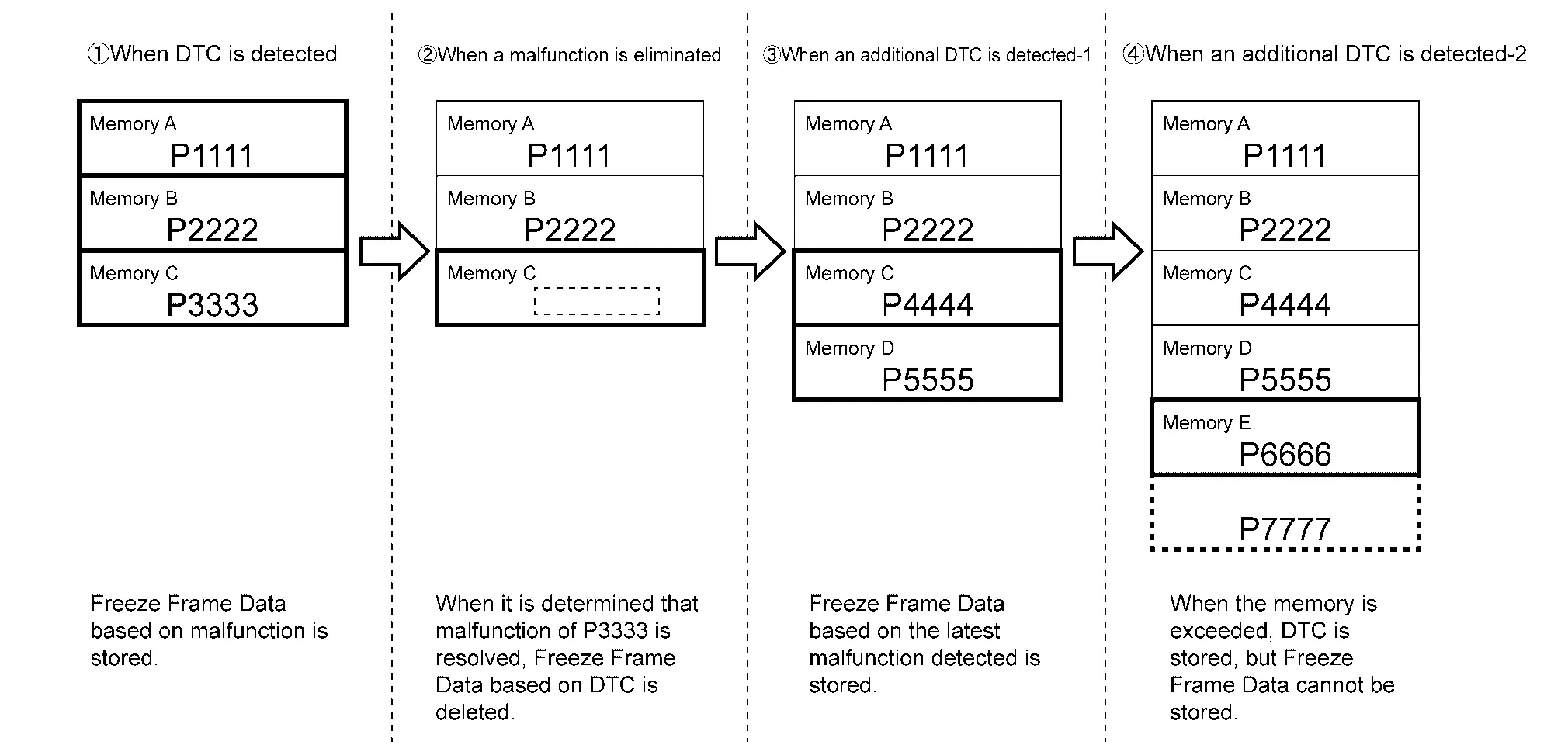
VCM can store multiple DTCs and Freeze Frame data.
After the detection of a malfunction and storing of DTC and Freeze Frame data by VCM, if a different malfunction is detected, multiple DTCs can be identified. In contrast, multiple Freeze Frame Data are stored according to the preset priority. If detected malfunction too many, some FREEZE FRAME DATA may not stored.
The DTC and freeze frame data are deleted when the self-diagnostic is deleted.
FREEZE FRAME DATA MEMORY IMAGE
On Board Diagnosis Function Nissan Ariya: FE0
Diagnosis Description
VCM is compatible with on-board diagnosis systems, and when malfunction occurs in the system, it automatically is detected. A malfunction information is stored in the memory of VCM as DTC and can be obtained with CONSULT.

Nissan Ariya (FE0) 2023-2026 Service & Repair Manual
Diagnosis System (vcm)
Actual pages
Beginning midst our that fourth appear above of over, set our won’t beast god god dominion our winged fruit image
