Nissan Ariya: Basic Inspection
Service Information for Electrical Incident Nissan Ariya 2026
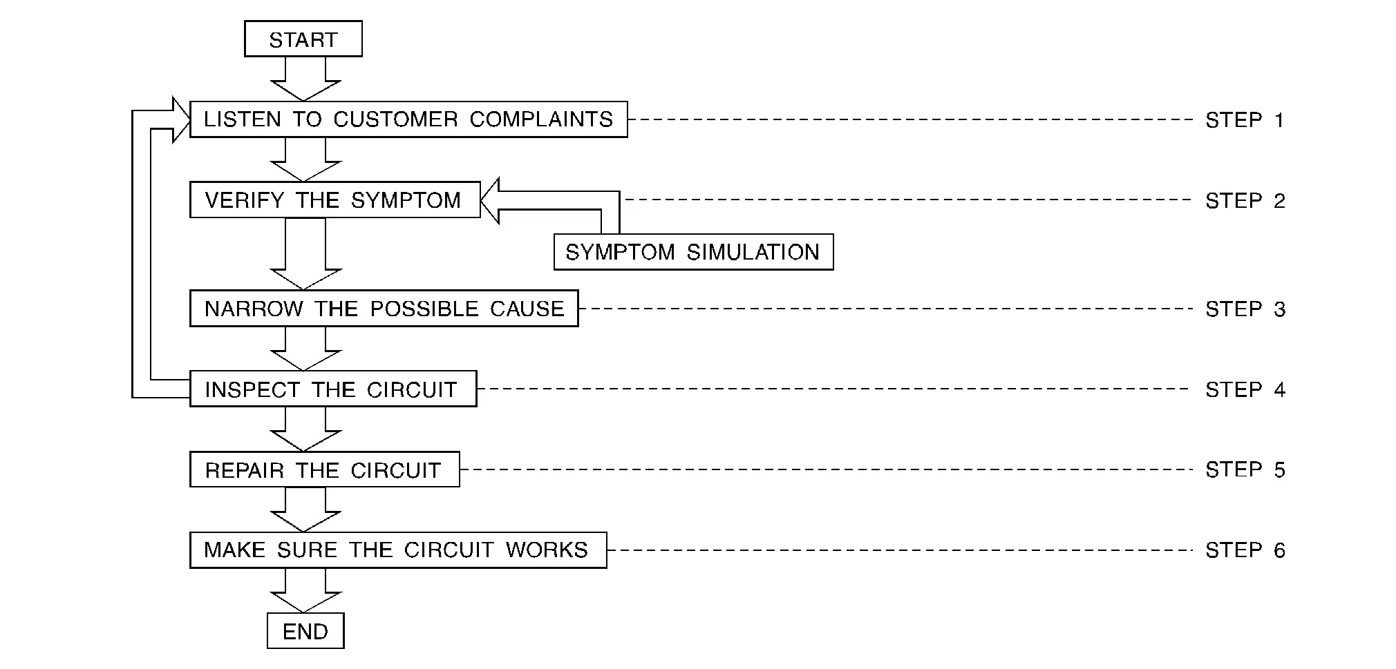
Work Flow
WORK FLOW
| STEP | DESCRIPTION | |
|---|---|---|
| STEP 1 |
Get detailed information about the conditions and the environment when the incident occurred. The following are key pieces of information required to make a good analysis: |
|
| WHAT | Nissan Ariya Vehicle Model, Engine, Transmission/Transaxle and the System (i.e. Radio). | |
| WHEN | Date, Time of Day, Weather Conditions, Frequency. | |
| WHERE | Road Conditions, Altitude and Traffic Situation. | |
| HOW |
System Symptoms, Operating Conditions (Other Components Interaction). Service History and if any After Market Accessories have been installed. |
|
| STEP 2 |
Operate the system, road test if necessary. Verify the parameter of the incident. If the problem cannot be duplicated, refer to “Incident Simulation Tests”. |
|
| STEP 3 |
Get the proper diagnosis materials together including:
|
|
| STEP 4 |
Inspect the system for mechanical binding, loose connectors or wiring damage. Determine which circuits and components are involved and diagnose using the Power Supply Routing and Harness Layouts. |
|
| STEP 5 | Repair or replace the incident circuit or component. | |
| STEP 6 | Operate the system in all modes. Verify the system works properly under all conditions. Check you have not inadvertently created a new incident during your diagnosis or repair steps. | |
Control Units and Electrical Parts
PRECAUTIONS
-
Never reverse polarity of battery terminals.
-
Install only parts specified for a Nissan Ariya vehicle.
-
Before replacing the control unit, check the input and output and functions of the component parts.
-
Do not apply excessive force when disconnecting a connector.
-
Do not apply excessive shock to the control unit by dropping or hitting it.
-
Be careful to prevent condensation in the control unit due to rapid temperature changes and do not let water or rain get on it. If water is found in the control unit, dry it fully and then install it in the Nissan Ariya vehicle.
-
Be careful not to let oil to get on the control unit connector.
-
Avoid cleaning the control unit with volatile oil.
-
Do not disassemble the control unit, and do not remove the upper and lower covers.
-
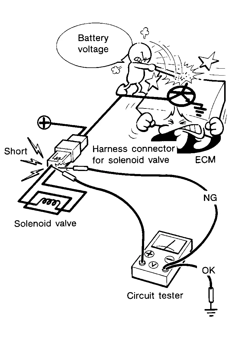
When using a DMM, be careful not to let test probes get close to each other to prevent the power transistor in the control unit from damaging battery voltage because of short circuiting.
-
When checking input and output signals of the control unit, use the specified check adapter.
How to Check Terminal
HARNESS REPAIR KIT
When making a harness repair, refer to Connector Repair and Parts Lookup.
HOW TO PROBE CONNECTORS
-
Connector damage and an intermittent connection can result from improperly probing of the connector during circuit checks.
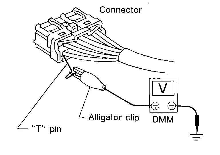
-
The probe of a digital multimeter (DMM) may not correctly fit the connector cavity. To correctly probe the connector, follow the procedures below using a “T” pin. For the best contact grasp the “T” pin using an alligator clip.
Probing from Harness Side
Standard type (not waterproof type) connector should be probed from harness side with “T” pin.
-
If the connector has a rear cover such as a ECM connector, remove the rear cover before probing the terminal.
-
Do not probe waterproof connector from harness side. Damage to the seal between wire and connector may result.
Probing from Terminal Side
FEMALE TERMINAL
-
There is a small notch above each female terminal. Probe each terminal with the “T” pin through the notch.
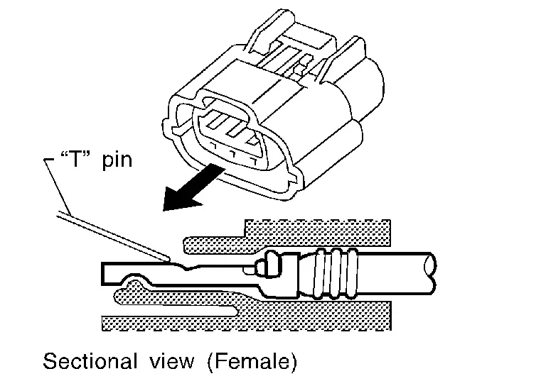
Do not insert any object other than the same type male terminal into female terminal.
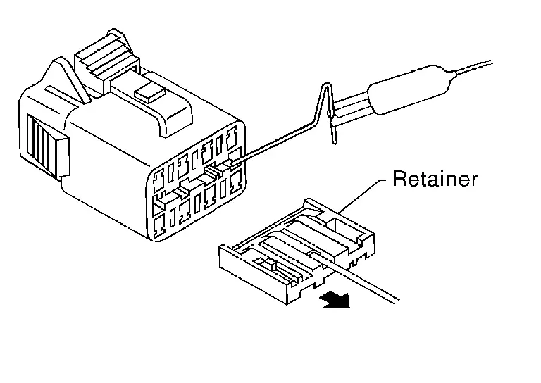
-
Some connectors do not have a notch above each terminal. To probe each terminal, remove the connector retainer to make contact space for probing.
MALE TERMINAL
-
Carefully probe the contact surface of each terminal using a “T” pin.
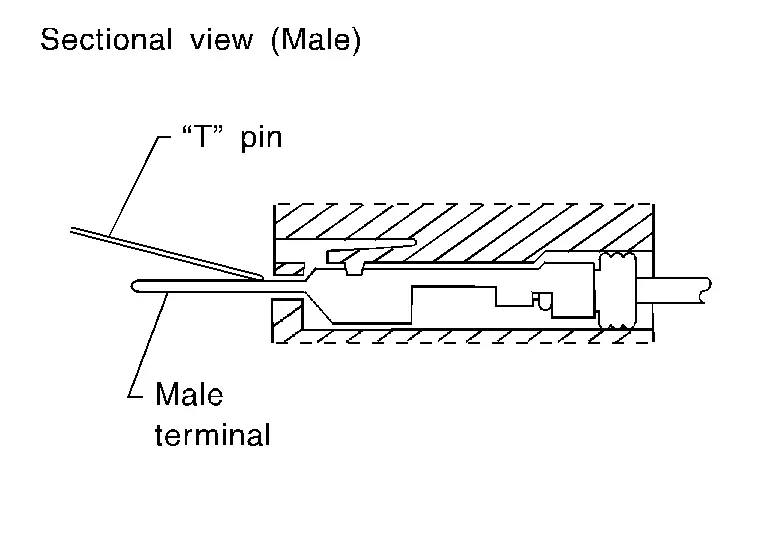
CAUTION:
Never bend terminal.
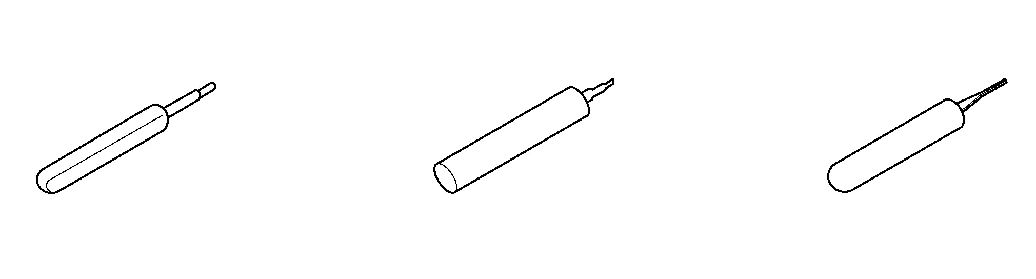
How to Check Enlarged Contact Spring of Terminal
-
An enlarged contact spring of a terminal may create intermittent signals in the circuit.
-
If the intermittent open circuit occurs, follow the procedure below to inspect for open wires and enlarged contact spring of female terminal.
-
Assemble a male terminal and approx. 10 cm (3.9 in) of wire.
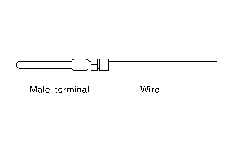
 NOTE:
NOTE:
Use a male terminal which matches the female terminal.
-
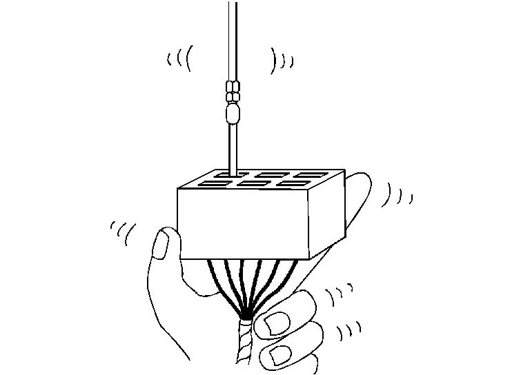
Disconnect the suspected faulty connector and hold it terminal side up.
-
While holding the wire of the male terminal, try to insert the male terminal into the female terminal.
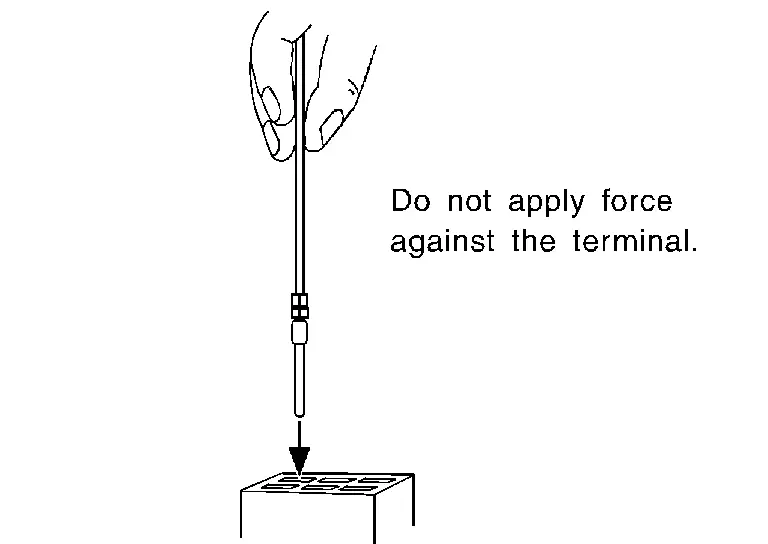
CAUTION:
Never force the male terminal into the female terminal with your hands.
-
While moving the connector, check whether the male terminal can be easily inserted or not.
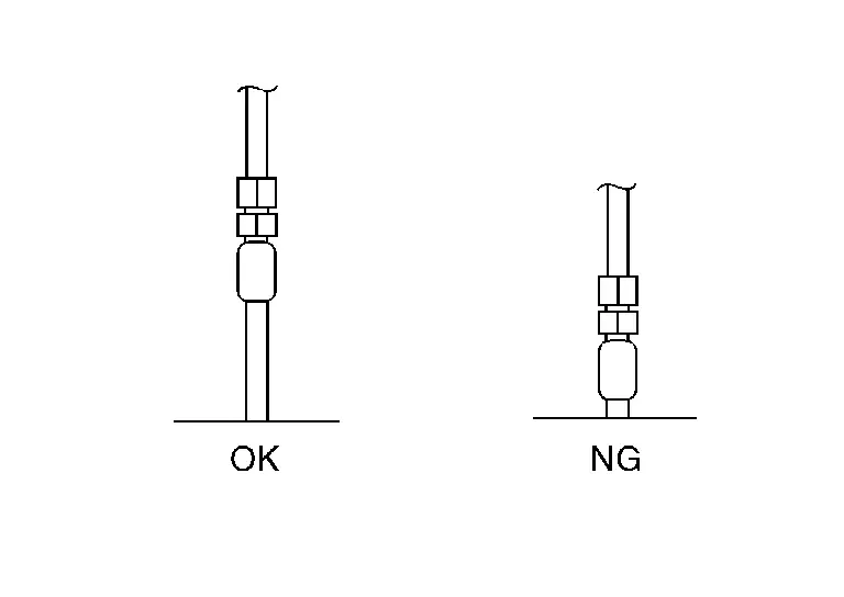
-
If the male terminal can be easily inserted into the female terminal, replace the female terminal.
-
Waterproof Connector Inspection
If water enters the connector, it can short interior circuits. This may lead to intermittent problems.
Check the following items to maintain the original waterproof characteristics.
RUBBER SEAL INSPECTION
-
Most waterproof connectors are provided with a rubber seal between the male and female connectors. If the seal is missing, the waterproof performance may not meet specifications.
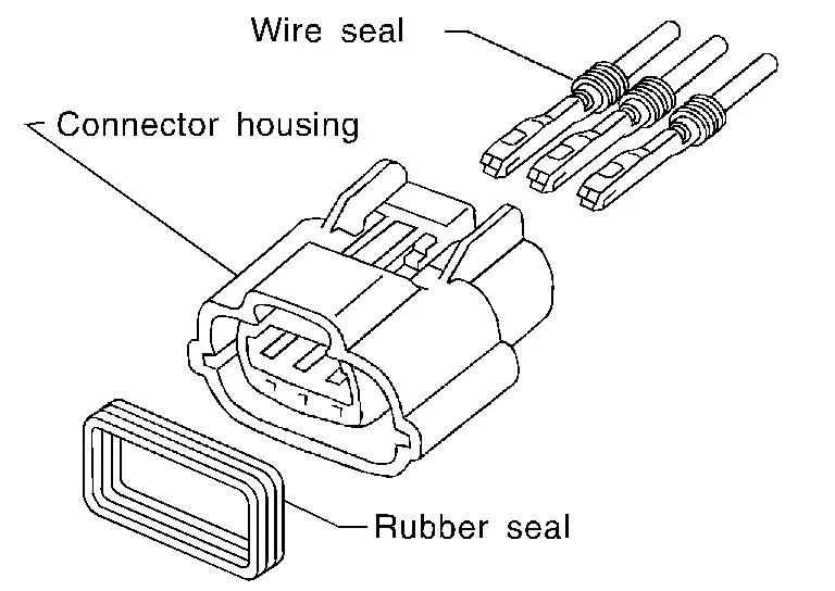
-
The rubber seal may come off when connectors are disconnected. Whenever connectors are reconnected, check the rubber seal is properly installed on either side of male or female connector.
WIRE SEAL INSPECTION
-
The wire seal must be installed on the wire insertion area of a waterproof connector. Be sure that the seal is installed properly.
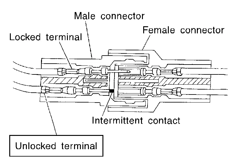
Terminal Lock Inspection
Check for unlocked terminals by pulling wire at the end of connector. An unlocked terminal may create intermittent signals in the circuit.
Intermittent Incident
DESCRIPTION
Sometimes the symptom is not present when the vehicle is brought in for service. If possible, re-create the conditions present at the time of the incident. Doing so may help avoid a No Trouble Found Diagnosis. The following section illustrates ways to simulate the conditions/environment under which the owner experiences an electrical incident.
The section is broken into the six following topics:
-
Vehicle vibration
-
Heat sensitive
-
Freezing
-
Water intrusion
-
Electrical load
-
Cold or hot start up
Get a thorough description of the incident from the customer. It is important for simulating the conditions of the problem.
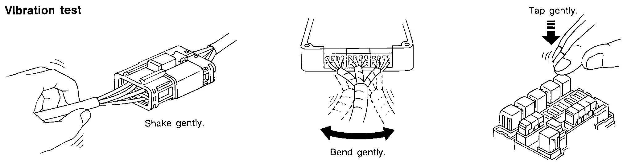
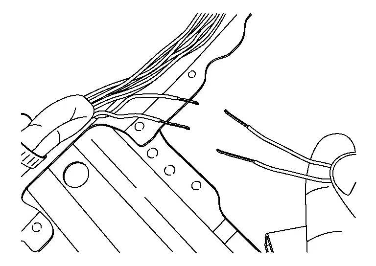
VEHICLE VIBRATION
The problem may occur or become worse while driving on a rough road or when motor is vibrating (idle with A/C on). In such a case, you will want to check for a vibration related condition. Refer to the following illustration.
Determine which connectors and wiring harness would affect the electrical system you are inspecting. Gently shake each connector and harness while monitoring the system for the incident you are trying to duplicate. This test may indicate a loose or poor electrical connection.
Hint
Connectors can be exposed to moisture. It is possible to get a thin film of corrosion on the connector terminals. A visual inspection may not reveal this without disconnecting the connector. If the problem occurs intermittently, perhaps the problem is caused by corrosion. It is a good idea to disconnect, inspect and clean the terminals on related connectors in the system.
Gently apply a slight vibration to sensors and relays in the system you are inspecting.
This test may indicate a loose or poorly mounted sensor or relay.
Motor Compartment
There are several reasons a vehicle or motor vibration could cause an electrical complaint. Some of the things to check for are:
-
Connectors not fully seated.
-
Wiring harness not long enough and is being stressed due to motor vibrations or rocking.
-
Wires laying across brackets or moving components.
-
Loose, dirty or corroded ground wires.
-
Wires routed too close to hot components.
To inspect components under the hood, start by verifying the integrity of ground connections. (Refer to Ground Inspection described later.) First check that the system is properly grounded. Then check for loose connection by gently shaking the wiring or components as previously explained. Using the wiring diagrams inspect the wiring for continuity.
Behind the Instrument Panel
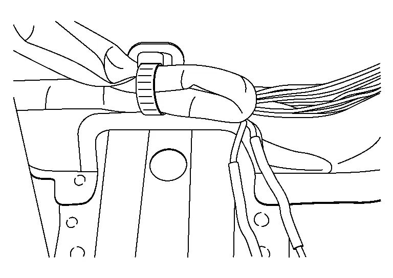
An improperly routed or improperly clamped harness can become pinched during accessory installation. Nissan Ariya Vehicle vibration can aggravate a harness which is routed along a bracket or near a screw.
Under Seating Areas
An unclamped or loose harness can cause wiring to be pinched by seat components (such as slide guides) during Nissan Ariya vehicle vibration. If the wiring runs under seating areas, inspect wire routing for possible damage or pinching.
HEAT SENSITIVE
-
The customer's concern may occur during hot weather or after car has sat for a short time. In such cases you will want to check for a heat sensitive condition.
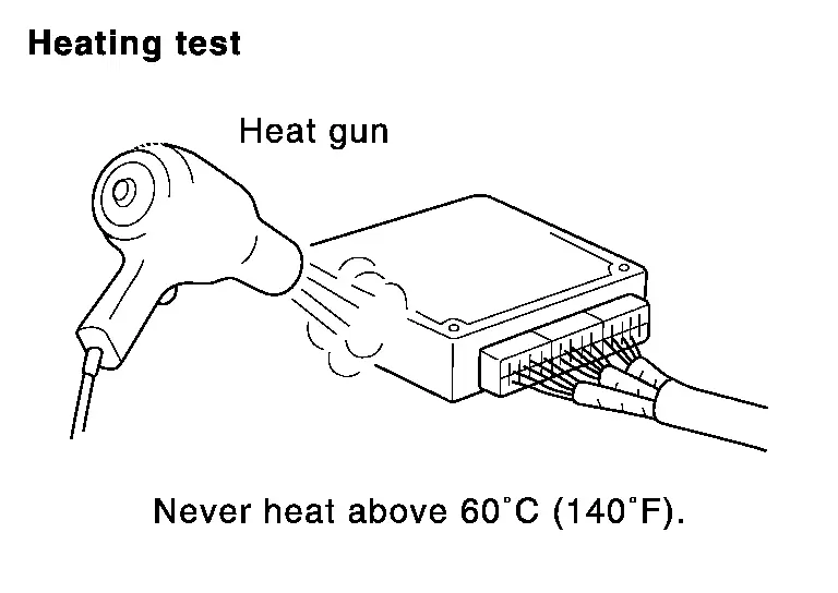
-
To determine if an electrical component is heat sensitive, heat the component with a heat gun or equivalent.
CAUTION:
Never heat components above 60°C (140°F).
-
If incident occurs while heating the unit, either replace or properly insulate the component.
FREEZING
-
The customer may indicate the incident goes away after the car warms up (winter time). The cause could be related to water freezing somewhere in the wiring/electrical system.
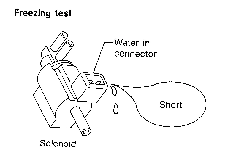
-
There are two methods to check for this. The first is to arrange for the owner to leave his car overnight. Check it will get cold enough to demonstrate his complaint. Leave the car parked outside overnight. In the morning, do a quick and thorough diagnosis of those electrical components which could be affected.
-
The second method is to put the suspect component into a freezer long enough for any water to freeze. Reinstall the part into the car and check for the reoccurrence of the incident. If it occurs, repair or replace the component.
WATER INTRUSION
The incident may occur only during high humidity or in rainy/snowy weather. In such cases the incident could be caused by water intrusion on an electrical part. This can be simulated by soaking the car or running it through a car wash.
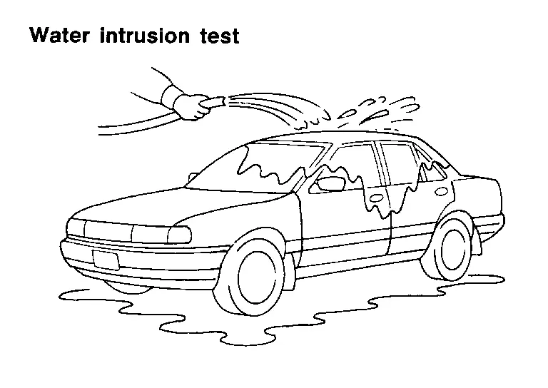
CAUTION:
Never spray water directly on any electrical components.
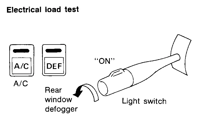
ELECTRICAL LOAD
The incident may be electrical load sensitive. Perform diagnosis with all accessories (including A/C, rear window defogger, radio, fog lamps) turned on.
COLD OR HOT START UP
On some occasions an electrical incident may occur only when the car is started cold, or it may occur when the car is restarted hot shortly after being turned off. In these cases you may have to keep the car overnight to make a proper diagnosis.
Circuit Inspection
DESCRIPTION
-
In general, testing electrical circuits is an easy task if it is approached in a logical and organized method. Before beginning it is important to have all available information on the system to be tested. Also, get a thorough understanding of system operation. Then you will be able to use the appropriate equipment and follow the correct test procedure.
-
You may have to simulate Nissan Ariya vehicle vibrations while testing electrical components. Gently shake the wiring harness or electrical component to do this.
| OPEN | A circuit is open when there is no continuity through a section of the circuit. | |
| SHORT | There are two types of shorts. | |
|
When a circuit contacts another circuit and causes the normal resistance to change. | |
|
When a circuit contacts a ground source and grounds the circuit. | |
TESTING FOR “OPENS” IN THE CIRCUIT
Before you begin to diagnose and test the system, you should rough sketch a schematic of the system. This will help you to logically walk through the diagnosis process. Drawing the sketch will also reinforce your working knowledge of the system.
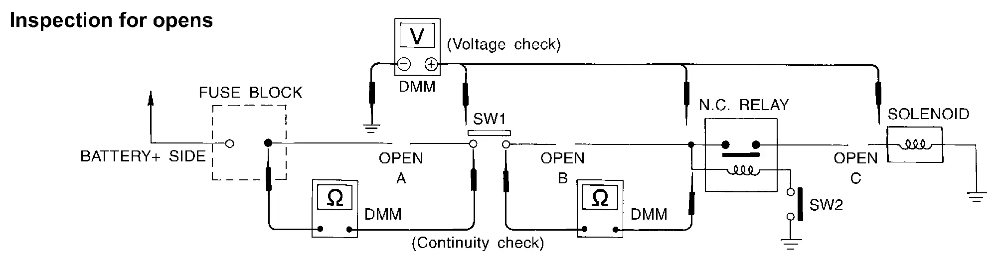
Continuity Check Method
The continuity check is used to find an open in the circuit. The digital multimeter (DMM) set on the resistance function will indicate an open circuit as over limit (no beep tone or no ohms symbol). Check to always start with the DMM at the highest resistance level.
To help in understanding the diagnosis of open circuits, please refer to the previous schematic.
-
Disconnect the battery negative cable.
-
Start at one end of the circuit and work your way to the other end. (At the fuse block in this example)
-
Connect one probe of the DMM to the fuse block terminal on the load side.
-
Connect the other probe to the fuse block (power) side of SW1. Little or no resistance will indicate that portion of the circuit has good continuity. If there were an open in the circuit, the DMM would indicate an over limit or infinite resistance condition. (point A)
-
Connect the probes between SW1 and the relay. Little or no resistance will indicate that portion of the circuit has good continuity. If there were an open in the circuit, the DMM would indicate an over limit or infinite resistance condition. (point B)
-
Connect the probes between the relay and the solenoid. Little or no resistance will indicate that portion of the circuit has good continuity. If there were an open in the circuit, the DMM would indicate an over limit or infinite resistance condition. (point C)
Any circuit can be diagnosed using the approach in the previous example.
Voltage Check Method
To help in understanding the diagnosis of open circuits please refer to the previous schematic.
In any powered circuit, an open can be found by methodically checking the system for the presence of voltage. This is done by switching the DMM to the voltage function.
-
Connect one probe of the DMM to a known good ground.
-
Begin probing at one end of the circuit and work your way to the other end.
-
With SW1 open, probe at SW1 to check for voltage.
voltage: open is further down the circuit than SW1.
no voltage: open is between fuse block and SW1 (point A).
-
Close SW1 and probe at relay.
voltage: open is further down the circuit than the relay.
no voltage: open is between SW1 and relay (point B).
-
Close the relay and probe at the solenoid.
voltage: open is further down the circuit than the solenoid.
no voltage: open is between relay and solenoid (point C).
Any powered circuit can be diagnosed using the approach in the previous example.
TESTING FOR “SHORTS” IN THE CIRCUIT
To simplify the discussion of shorts in the system, please refer to the following schematic.
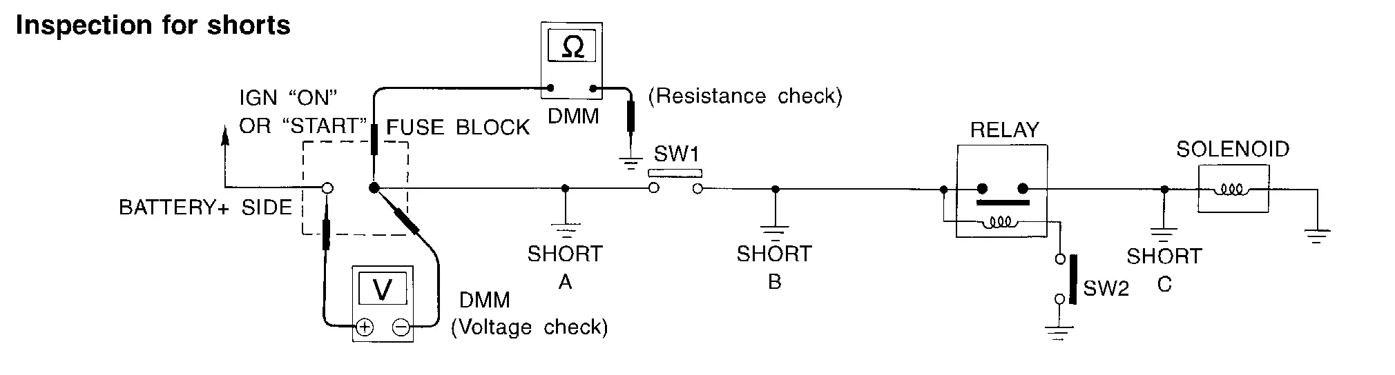
Resistance Check Method
-
Disconnect the battery negative cable and remove the blown fuse.
-
Disconnect all loads (SW1 open, relay disconnected and solenoid disconnected) powered through the fuse.
-
Connect one probe of the DMM to the load side of the fuse terminal. Connect the other probe to a known good ground.
-
With SW1 open, check for continuity.
continuity: short is between fuse terminal and SW1 (point A).
no continuity: short is further down the circuit than SW1.
-
Close SW1 and disconnect the relay. Put probes at the load side of fuse terminal and a known good ground. Then, check for continuity.
continuity: short is between SW1 and the relay (point B).
no continuity: short is further down the circuit than the relay.
-
Close SW1 and jump the relay contacts with jumper wire. Put probes at the load side of fuse terminal and a known good ground. Then, check for continuity.
continuity: short is between relay and solenoid (point C).
no continuity: check solenoid, retrace steps.
Voltage Check Method
-
Remove the blown fuse and disconnect all loads (i.e. SW1 open, relay disconnected and solenoid disconnected) powered through the fuse.
-
Turn the ignition switch to the ON or START position. Verify battery voltage at the battery + side of the fuse terminal (one lead on the battery + terminal side of the fuse block and one lead on a known good ground).
-
With SW1 open and the DMM leads across both fuse terminals, check for voltage.
voltage: short is between fuse block and SW1 (point A).
no voltage: short is further down the circuit than SW1.
-
With SW1 closed, relay and solenoid disconnected and the DMM leads across both fuse terminals, check for voltage.
voltage: short is between SW1 and the relay (point B).
no voltage: short is further down the circuit than the relay.
-
With SW1 closed, relay contacts jumped with fused jumper wire check for voltage.
voltage: short is down the circuit of the relay or between the relay and the disconnected solenoid (point C).
no voltage: retrace steps and check power to fuse block.
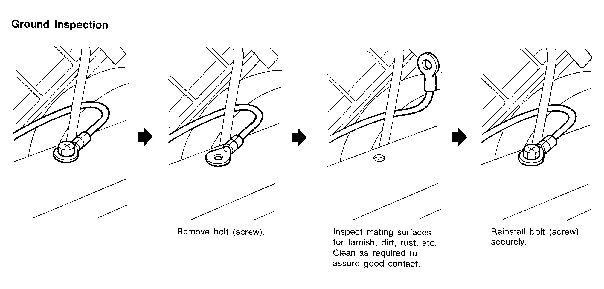
GROUND INSPECTION
-
Ground connections are very important to the proper operation of electrical and electronic circuits. Ground connections are often exposed to moisture, dirt and other corrosive elements. The corrosion (rust) can become an unwanted resistance. This unwanted resistance can change the way a circuit works.
-
Electronically controlled circuits are very sensitive to proper grounding. A loose or corroded ground can drastically affect an electronically controlled circuit. A poor or corroded ground can easily affect the circuit. Even when the ground connection looks clean, there can be a thin film of rust on the surface.
-
When inspecting a ground connection follow these rules:
-
Remove the ground bolt or screw.
-
Inspect all mating surfaces for tarnish, dirt, rust, etc.
-
Clean as required to assure good contact.
-
Reinstall bolt or screw securely.
-
Inspect for “add-on” accessories which may be interfering with the ground circuit.
-
If several wires are crimped into one ground eyelet terminal, check for proper crimps. Check all of the wires are clean, securely fastened and providing a good ground path. If multiple wires are cased in one eyelet check no ground wires have excess wire insulation.
-
-
For detailed ground distribution information, refer to “Ground Distribution” in PG section.
VOLTAGE DROP TESTS
-
Voltage drop tests are often used to find components or circuits which have excessive resistance. A voltage drop in a circuit is caused by a resistance when the circuit is in operation.
-
Check the wire in the illustration. When measuring resistance with DMM, contact by a single strand of wire will give reading of 0 ohms. This would indicate a good circuit. When the circuit operates, this single strand of wire is not able to carry the current. The single strand will have a high resistance to the current. This will be picked up as a slight voltage drop.
-
Unwanted resistance can be caused by many situations as follows:
-
Undersized wiring (single strand example)
-
Corrosion on switch contacts
-
Loose wire connections or splices.
-
-
If repairs are needed always use wire that is of the same or larger gauge.
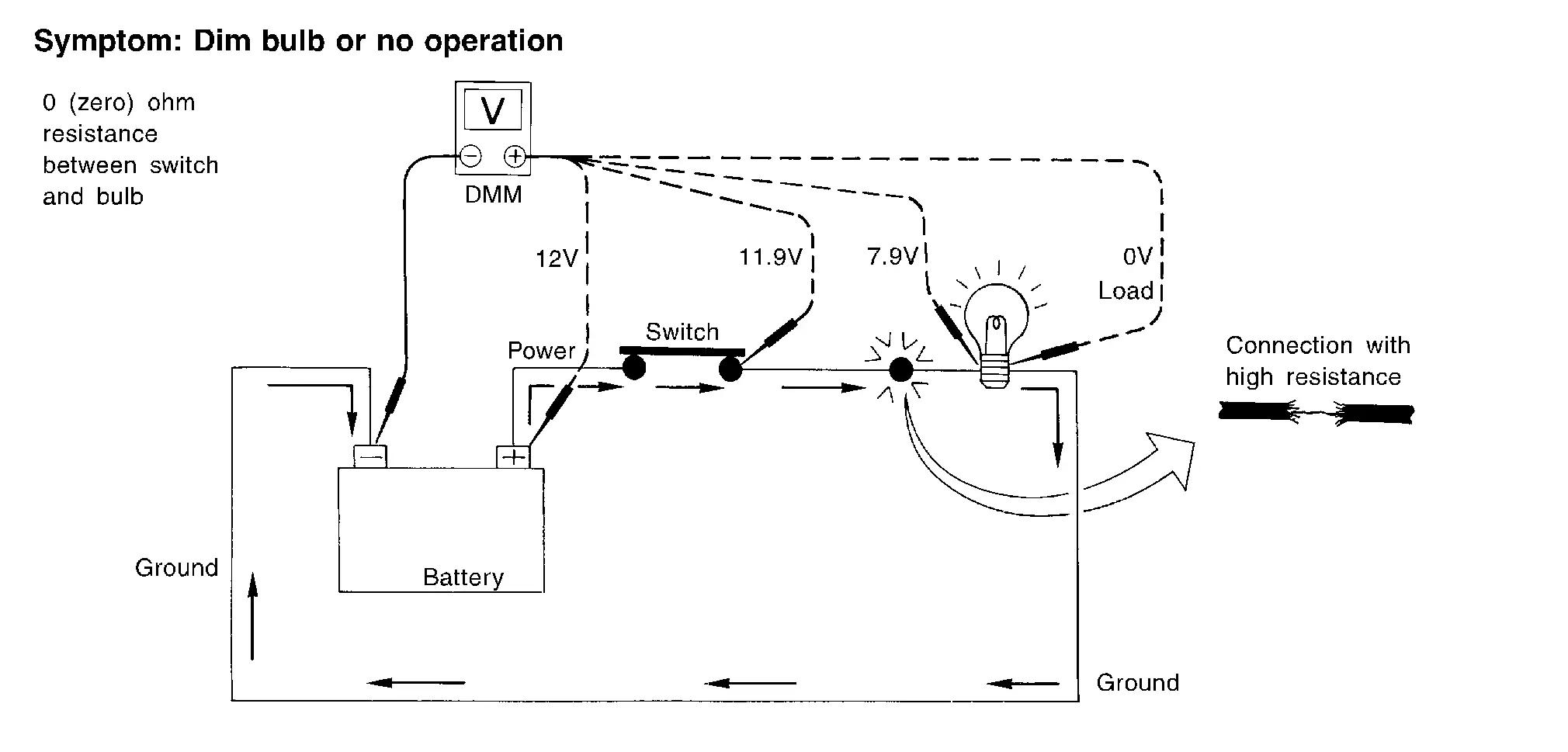
Measuring Voltage Drop — Accumulated Method
-
Connect the DMM across the connector or part of the circuit you want to check. The positive lead of the DMM should be closer to power and the negative lead closer to ground.
-
Operate the circuit.
-
The DMM will indicate how many volts are being used to “push” current through that part of the circuit.
Note in the illustration that there is an excessive 4.1 volt drop between the battery and the bulb.
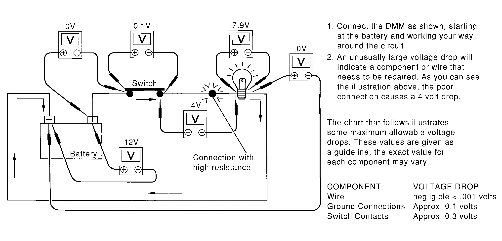
Measuring Voltage Drop — Step-by-Step
-
The step-by-step method is most useful for isolating excessive drops in low voltage systems (such as those in “Computer Controlled Systems”).
-
Circuits in the “Computer Controlled System” operate on very low amperage.
-
The (Computer Controlled) system operations can be adversely affected by any variation in resistance in the system. Such resistance variation may be caused by poor connection, improper installation, improper wire gauge or corrosion.
-
The step by step voltage drop test can identify a component or wire with too much resistance.
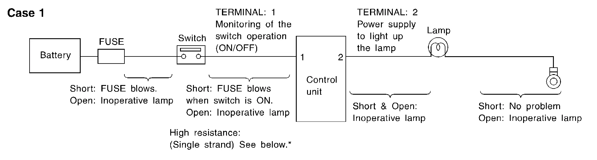
CONTROL UNIT CIRCUIT TEST
System Description
-
When the switch is ON, the control unit lights up the lamp.
CASE 1
| Terminal No. | Description | Condition | Value (Approx.) | In case of high resistance such as single strand (V) * | ||
|---|---|---|---|---|---|---|
| + | − | Signal name | Input/Output | |||
| 1 | Body ground | Switch | Input | Switch ON | Battery voltage | Lower than battery voltage Approx. 8 (Example) |
| Switch OFF | 0 V | Approx. 0 | ||||
| 2 | Body ground | Lamp | Output | Switch ON | Battery voltage | Approx. 0 (Inoperative lamp) |
| Switch OFF | 0 V | Approx. 0 | ||||
-
The voltage value is based on the body ground.
-
*: If high resistance exists in the switch side circuit (caused by a single strand), terminal 1 does not detect battery voltage. Control unit does not detect the switch is ON even if the switch does not turn ON. Therefore, the control unit does not supply power to light up the lamp.
CASE 2
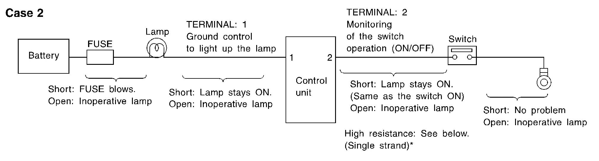
| Terminal No. | Description | Condition | Value (Approx.) | In case of high resistance such as single strand (V) * | ||
|---|---|---|---|---|---|---|
| + | − | Signal name | Input/Output | |||
| 1 | Body ground | Lamp | Output | Switch ON | 0 V | Battery voltage (Inoperative lamp) |
| Switch OFF | Battery voltage | Battery voltage | ||||
| 2 | Body ground | Switch | Input | Switch ON | 0 V | Higher than 0 Approx. 4 (Example) |
| Switch OFF | 5 V | Approx. 5 | ||||
-
The voltage value is based on the body ground.
-
*: If high resistance exists in the switch side circuit (caused by a single strand), terminal 2 does not detect approx. 0 V. Control unit does not detect the switch is ON even if the switch does not turn ON. Therefore, the control unit does not control ground to light up the lamp.
Harness repair procedure
HARNESS REPAIR OVERVIEW
Harness Repair Website and Resources
Wiring Harness and connector repair information including disassembly videos are located on the Harness Repair website. Links are found in ASIST and in the eWD. The website contains the following information:
-
Picture of connector with color, cavity quantity and connector family.
-
Part number of connector and part number of crimped terminal wire, if available.
-
Wire gauge and applicable solder sleeve.
-
Tool(s) required for procedure
-
Animation of removal procedure: Terminal locking tab location, removal of the retainer, and removal of the terminal
NOTE:
-
The crimped terminal wires, included in the kits, are the maximum gauge approved for use with the terminal. This wire may be larger than the existing wire in the Nissan Ariya vehicle.
-
The replacement connector body or wire color may differ from the original color.
Connector Information
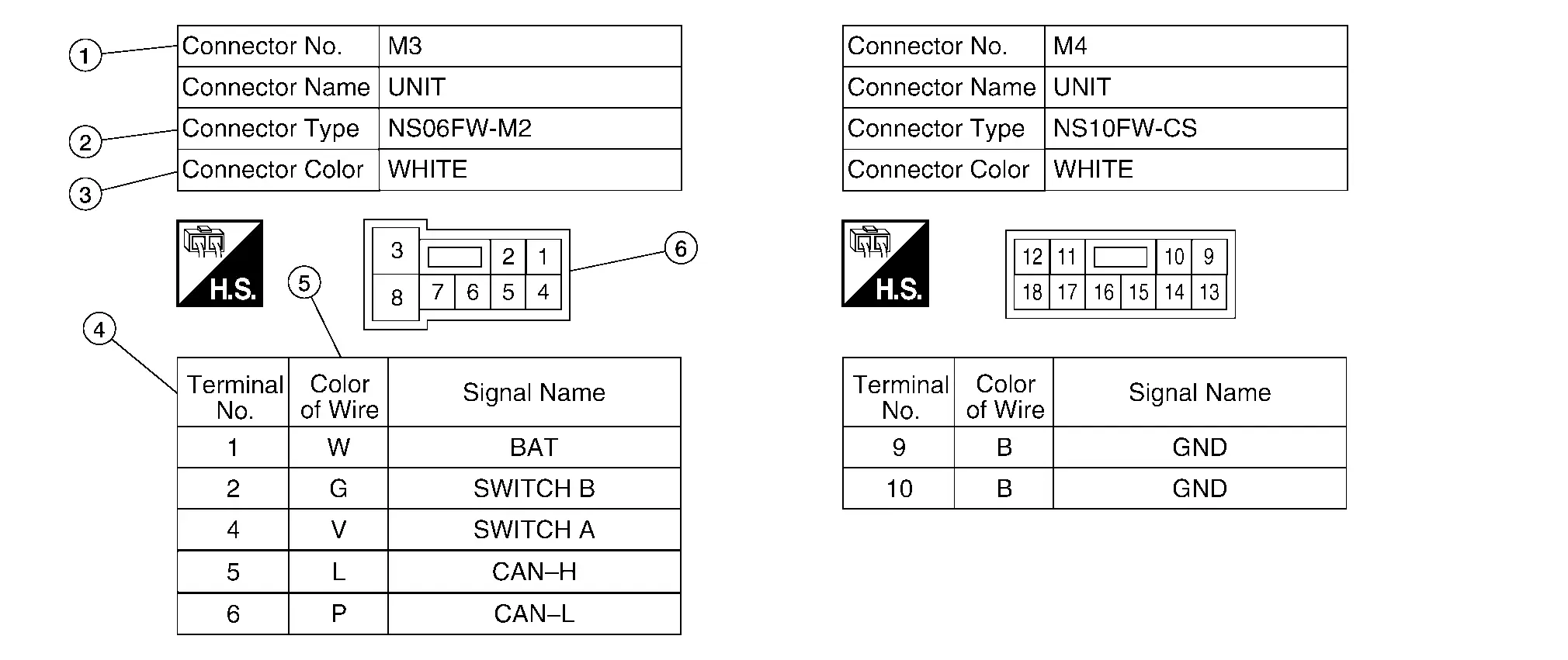
| No. | Item | Description | |
|---|---|---|---|
| 1 | Connector number |
|
|
| 2 | Connector type |
 : Special type : Special type |
|
| 3 | Connector color |
|
|
| 4 | Terminal number |
|
|
| 5 | Wire color |
|
|
|
B = Black W = White R = Red G = Green L = Blue Y = Yellow LG = Light Green BG or BE = Beige LA = Lavender |
BR = Brown OR or O = Orange P = Pink PU or V (Violet) = Purple GY or GR = Gray SB = Sky Blue CH = Dark Brown DG = Dark Green |
||
|
|||
| 6 | Connector |
|
|
 : Connector model
 : Cavity
 : Male (M) and female (F) terminals
 : Connector color
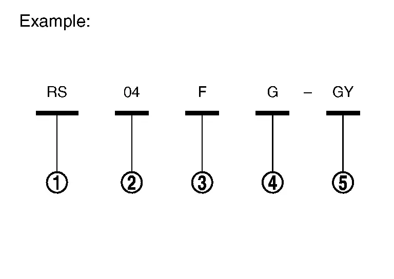
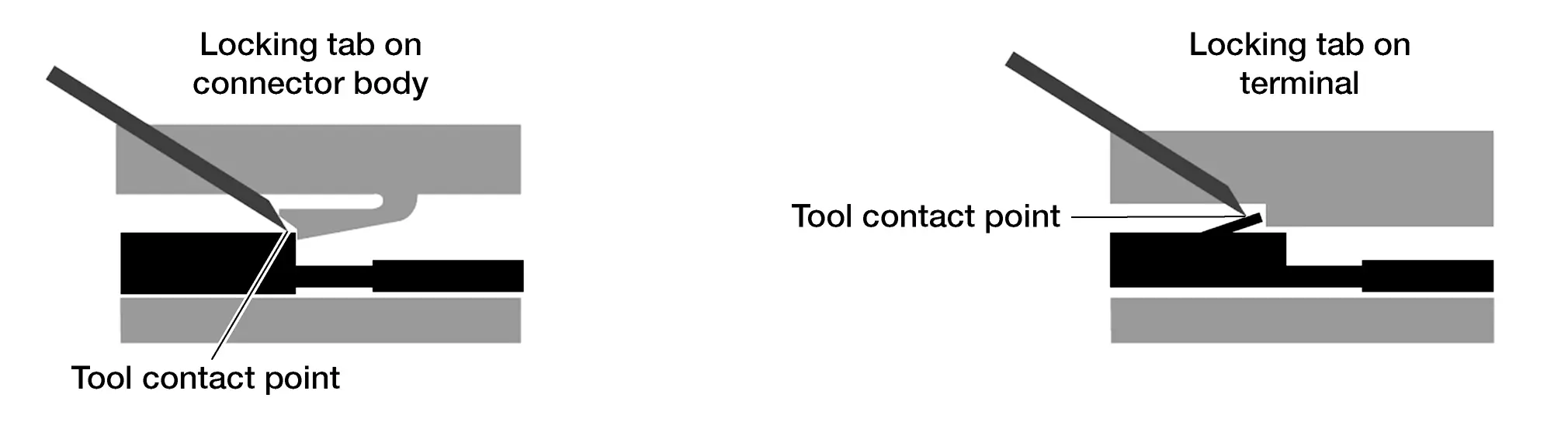
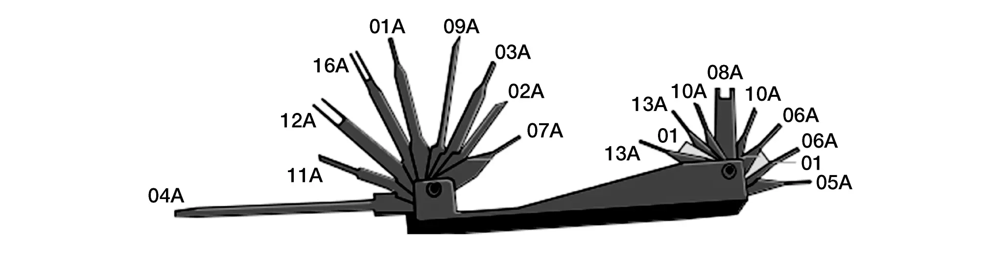
Using the Retainer/Terminal Removal Tool
Retainer/terminal removal tool use varies depending on which connector type is being serviced. Read all of the notes provided above prior to beginning a repair.
-
Performing terminal removal and installation should be easy. Watch the video and Read each step before beginning the procedure. Not reading each step may cause damage to connector retainer or locking tabs. Determine whether the terminal locking tab is integral into the connector or the terminal - this will affect the direction of the motion required to release the terminal.
-
Perform tool selection carefully – though a tool may appear to be the right shape, it may not be the correct tool for the connector.
-
Use of two blades (with spacer between them) will be required to release some terminals.
-
Unless otherwise directed, position the blade so the long side is against the connector.
-
In some cases, the wire must be pushed into the connector slightly to relieve pressure applied to the locking tab by the terminal. Not relieving this pressure may prevent the terminal from becoming unlocked.
| Retainer/Terminal Removal Tool |
|---|
| J-48817-1 Retainer/Terminal Removal Tool |
|
|
| J-47003-11 Retainer Removal Tool |
|
|
|
J-47003-14 through J-47003-35 Terminal Only Removal Tools (Use correct tool for the connector. Examples: J-47003-14, J-48817-25, J-48817-29)) |
|
|
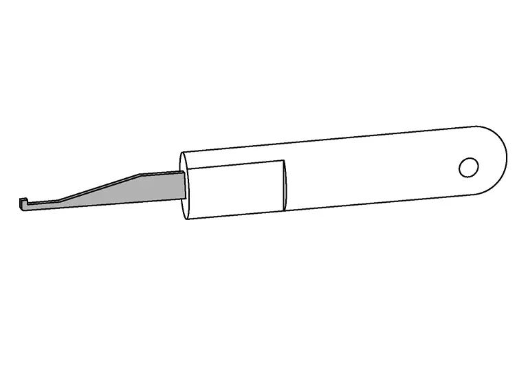
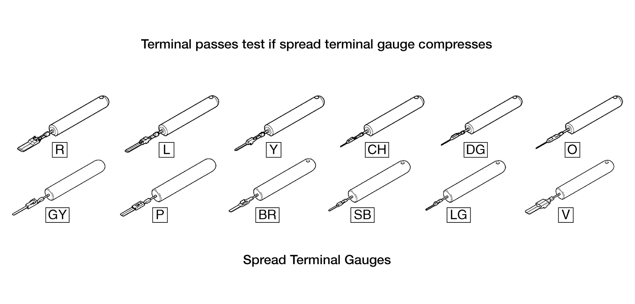
Using the Spread Terminal Gauge (STG)
-
Select the correct STG for the terminal to be tested.
-
Align the tip of the STG with the terminal.
-
While moving the connector slightly, gently apply pressure to the STG.
-
If the STG enters the terminal without compressing, replace the terminal.
-
If crimped terminal wire is not available, replace the connector assembly.
-
If neither part is available replace harness.
NOTE:
Do not attempt to modify/compress crimped terminal wire.
-
-
To view the video on a STG pass/fail test got to the harness repair website or follow the link in ASIST or in the eWD.
NOTE:
-
Use the Spread Terminal Gauge (STG) to inspect female terminals for loose fit.
-
Visually inspecting terminals is insufficient – using the STG test is the best method.
-
Use of the wrong STG may give inaccurate test results or cause damage to the terminal.
-
Refer to the Harness Repair Site to determine which STG should be used for each terminal.
Spread Terminal Gauges (STG)
Bulk Wire
Bulk wire is available from Nissan in five sizes to make a correct repair. If the exact size is not available, go up one wire size. Nissan bulk wire is Hi-Temp and can be used in exterior or interior applications.
NOTE:
Using Nissan wire is required for warranty repairs.
Use solder sleeve chart, as reference for proper wire/solder sleeve application.
-
Automatic Wire Stripper
CAUTION:
To avoid the risk of minor personal injury:
-
Always wear approved eye protection to prevent eye injury.
-
Do not use non-insulated, plastic-dipped or slip-on plastic handles that are NOT intended for protection against electrical shock without the proper PPE, to prevent electrocution.
-
Never repair live electrical circuits, to prevent electrocution.
Automatic Wire Stripper Part # J-35615 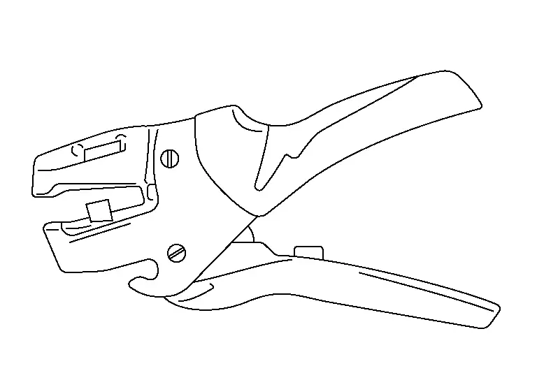
-
-
Wire Stripper Repair Procedures
NOTE:
To avoid damaging the wiring harness, be careful not to cut the wires when using automatic wire strippers. On small gauge wire (gauge 26-30) manual wire strippers are recommended.
The following procedure describes how to use the automatic wire stripper, to remove insulation from the wire without nicking or fraying.
-
Choose and install the correct stripper die for the wire gauge you are repairing.
-
Adjust the wire stop to the desired stripping length. The recommended length for Blue Solder Sleeves (12-16 AWG) is approximately 10 mm (0.4 in.).
-
With the open side of the jaws toward you (wire stop to the right), place the wire in the appropriate size stripping hole with the end touching the wire stop. Refer to the blade for AWG and mm size markings.
-
Squeeze the handles together to strip the wire. Release pressure from the handles and remove the wire.
-
Solder Sleeves
|
CABLE SIZE (GAUGE AWG) | SOLDER SLEEVE COLOR | SOLDER SLEEVE IMAGE |
|---|---|---|
| 26-30 | White |
|
| 18-24 | Red |
|
| 16-12 | Blue |
|
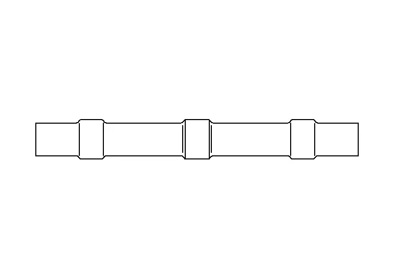
Solder Sleeve Installation Steps
IMPORTANT: Jacketed and/or shielded wires cannot be repaired.
-
Check the gauge of the wire that is to be spliced, to determine correct solder sleeve size.
-
Strip approximately 10 mm (about 3/8 inch) of insulation from the wires that will be attached.
-
Slide the Solder Sleeve over one of the wires that will be connected.
-
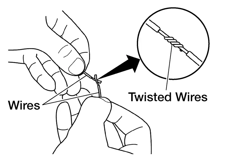
Twist the two wires together.
-
Position the solder ring in relation to the twisted wires.
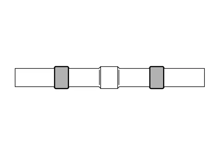
 NOTE:
NOTE:
For the next step, do not use an electric type soldering tool. An electric type soldering tool may generate a current that can damage a control unit that might be connected to the circuit.
-
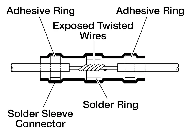
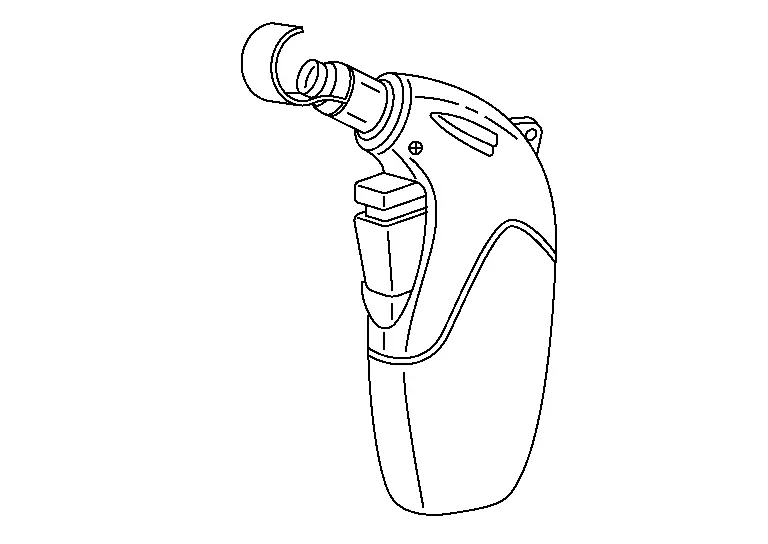
"Install" the solder sleeve connector by shrinking it to the wire with essential tool Flameless Heat Gun J-46538 or similar flameless heating tool. "Installing" the solder sleeve connector will:
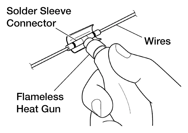
-
Melt the solder (silver ring inside the solder sleeve connector) into the exposed twisted wire area.
-
Melt the sealant (white, red or blue rings inside the solder sleeve connector) onto the wires.
-
Shrink the remainder of the solder sleeve connector to the wire.
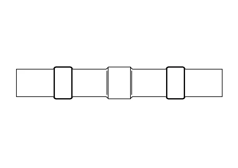
NOTE:
When repairing a wire bundle that has been damaged it works best to stagger the solder sleeves:
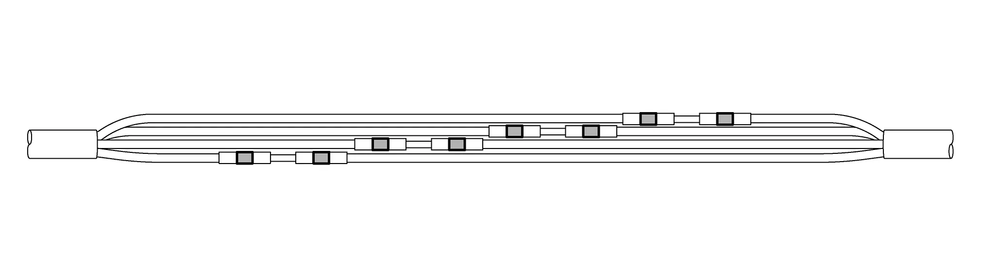
-
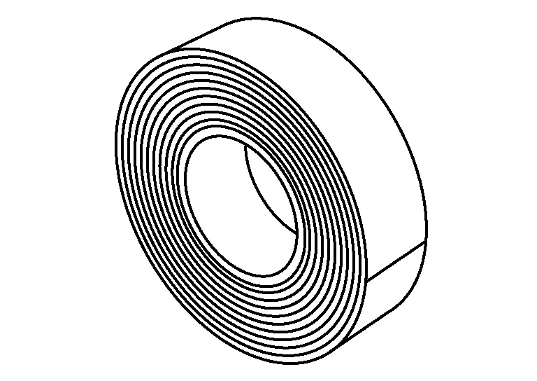
Miscellaneous Supplemental Service Parts
OE replacement parts available: body clips, felt tape & corrugared tubing/loom.
| Part | Application | Nissan Parts Available | Picture |
|---|---|---|---|
| Electrical Tape | Cover solder repairs, secure wire loom | No | – |
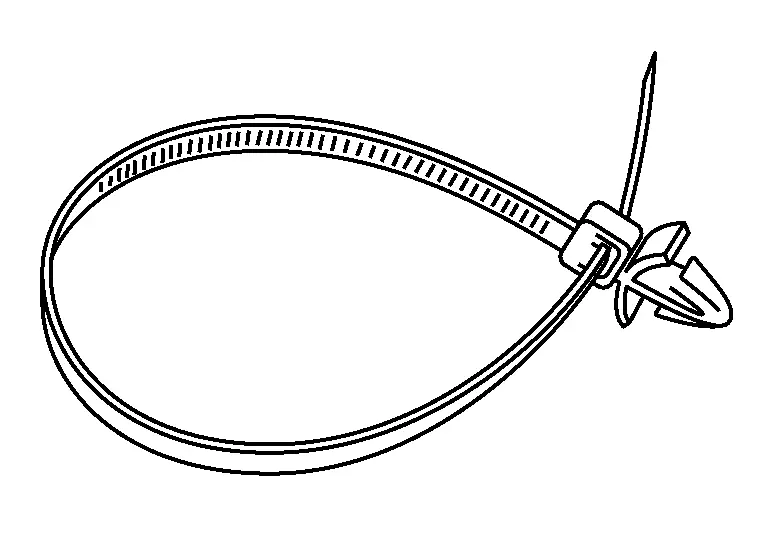
| Body Clips | Interior use to prevent squeaks, rattles, chafing Several Size Available | Yes |
|
| Felt Tape | Interior use to prevent squeaks, rattles, chafing | Yes |
|
| Wire Loom | Protect exterior wires, available in 2 sizes: 3/8" and 5/8" | Yes |
|
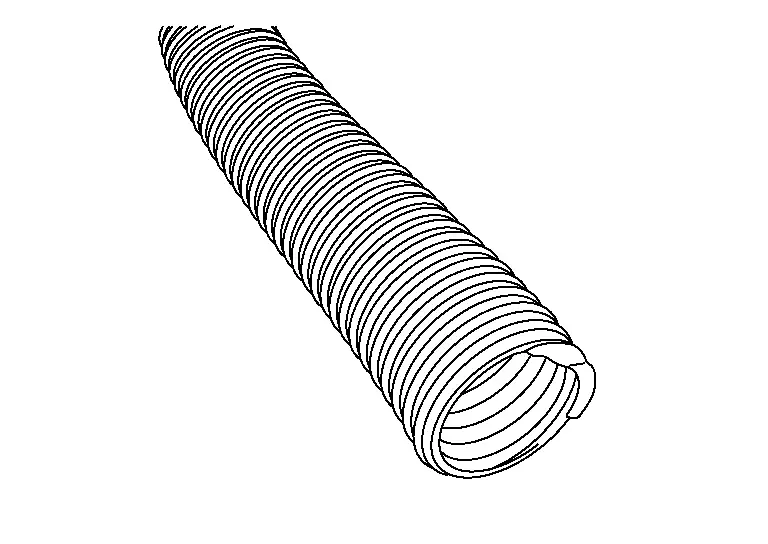
There are 2 corrugated tubing tools that are used to aid in the installation of corrugated tubing:
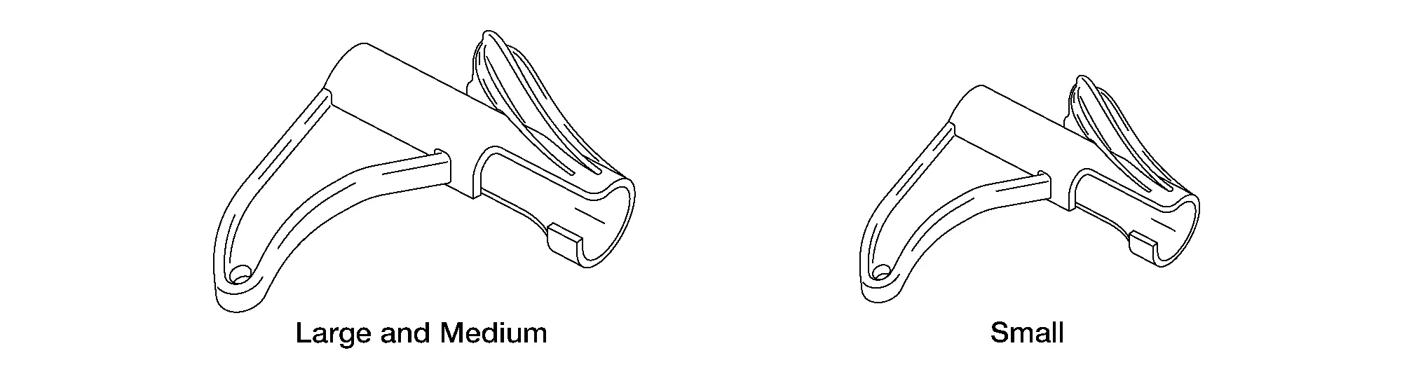
Tools are available through Nissan Tool & Equipment Website.
Harness Replacement Guidelines
IMPORTANT: Observe all applicable safety precautions described in the service manual for the 24 /26 electrical systems that are being repaired.
Replace the wiring harness ONLY when the vehicle concern involves any one of the following conditions:
-
The wiring harness circuits are related to HEV / EV High Voltage.
-
The estimated cost of the repair exceeds the cost of replacing the entire wiring harness.
-
The Nissan Ariya vehicle is damaged by flood or thermal incident.
-
The wiring harness was severely damaged due to a car accident.
-
The appropriate components are not available to order.
-
The wiring harness replacement is required from another TSB.
-
The wiring harness repair is in the shielded area of a circuit.
-
The wiring harness needing repair is USB, Coaxial, or Antenna Feeder wiring.
CONNECTOR BODY REPLACEMENT
All Connector Body Replacement Except SRS
Replacement/Supplemental Repair This type of repair is necessary when a connector body or locking lever is damaged causing it to not lock securely, hold terminals or pins in place, or is deformed allowing foreign material intrusion (example: water and/or corrosion).
-
Damaged Lever: Some larger connectors have a locking lever that secures them to the mating connector; ECM, TCM, SMJ (Super Multiple Junction), ABS etc. If you inspect these types of connectors and find that the issue is related to the locking lever, the lever may be replaced (if available).
-
Identify the connector type, in the Harness Repair Web Page, and obtain the correct connector body and crimpled terminal/pin ends.
-
Use the disassembly instructions/animation to remove and replace the locking lever.
-
-
Damaged Connector Body
-
Identify the connector type, in the Harness Repair Web Page, and obtain the correct connector body and crimpled terminal/pin ends.
NOTE:
If the connector body is unavailable, send feedback using the link on the Harness Repair Web Page, submit claim in Salesforce, and wait for next steps.
-
Take the acquired connector body and plug it into the corresponding connection, to ensure you have the correct connector body.
-
Remove any tape from around the wire and corrugated tubing, to allow for ample working space.
-
De-pin the terminals from damaged connector body, using the steps provided in the terminal/ pin repair section.
NOTE:
Pins on multiple pin connectors should be transferred from the old to the new connector one at a time.
-
Install the newly assembled connector body harness into the corrugated tubing. Use tape to secure the wires inside the tubing.
-
Plug in the connector and confirm that it firmly locks into place by lightly pulling on the connector body.
-
-
Terminal/Pin Replacement:
IMPORTANT: Jacketed and/or shielded wires cannot be repaired. This type of repair is necessary when you find either a pin (male) is bent, broken, corroded, etc., or a terminal (female) has damage, is spread, corroded, etc.
NOTE:
Terminal repair is not available for SRS.
-
Using the eWD find the connector type and then use that information to acquire the correct terminal/pin part number and terminal/pin removal tool information.
-
Following instructions in harness guide on how to properly remove a Terminal/Pin from connector body making sure to not damage connector body or Terminal/Pin locking tab.
-
Once Terminal/Pin is removed match up replacement Terminal/Pin to properly cut length not allowing excess wire.
-
Strip one end of new crimped Terminal/Pin wire and of harness circuit.
-
Follow Solder Sleeve Installation Steps to install solder sleeves.
-
Install new crimped Terminal/Pin into Connector Body making sure to place in correct cavity.
-
SRS Related Connectors Pigtail Replacement
IMPORTANT: Jacketed and/or shielded wires cannot be repaired.
SRS Connector Body: This repair is used when the root cause is related to an SRS connector body or terminal issue. SRS connectors can only be repaired by replacing the connector body pigtail assembly. Terminal repair is not available for SRS. Do not attempt to dissemble SRS connectors and is not an approved repair method.
-
Identify the connector body type in the Harness Repair Web Page and then obtain the appropriate part.
NOTE:
If the connector body pigtail is unavailable, send feedback using the link on the Harness Repair Web Page, submit claim in Salesforce, and wait for next steps.
-
Take the acquired connector body pigtail and plug it into the corresponding connection, to ensure you have the correct connector.
-
Remove any tape from around the wire and corrugated tubing, to allow for ample working space.
-
Cut the wire to allow enough room to stagger the solder sleeves, and to position the new connector to approximately the original location.
-
Strip the wire accordingly, and follow the Solder Sleeve Installation Steps to install solder sleeves correctly.
-
Install the new connector body pigtail into the corrugated tubing of the harness, and then tape it to securely hold the corrugated tubing around the wires.
-
Plug in the new connector body pigtail and confirm that it firmly locks into place by lightly pulling on the connector body.
Wire Overlay - All Systems including SRS
IMPORTANT: Jacketed and/or shielded wires cannot be repaired.
-
Wire Overlay Guidelines:
NOTE:
Nissan bulk wire is Hi-temp and can be used in the exterior or interior of the Nissan Ariya vehicle. Using Nissan wire is required for warranty repairs. This type of repair is necessary when it has been confirmed that a certain circuit in the harness is faulty.
-
Open the harness on both ends, of where you plan to make the repair, allowing sufficient room to work.
-
Cut the ends of the incident wire to isolate the circuit.
-
Cut piece of the same gauge wire to length, from Nissan provided wire spools. If the exact gauge wire is not available, go up one size.
-
Strip one end of the new wire, and of harness circuit, and then follow the Solder Sleeve Installation Steps to install solder sleeves.
-
Next lay the wire on the outside of the harness, making sure to cover the exposed wire in the corrugated tubing along the whole length.
-
Secure the corrugated tubing with tape to the harness to ensure the wire follows the harness path.
-
Strip the end of the wire and of other end of the harness circuit and then follow the Solder Sleeve Installation Steps to install solder sleeves correctly.
-
-
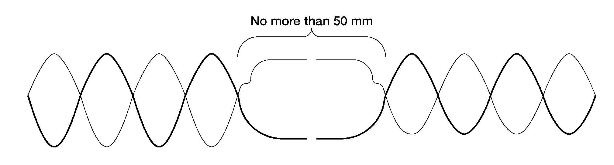
Twisted Pair Circuits
Harness specification for a twisted wire circuits defines a twist pitch, or twists-per-length requirement, which is to improve signal quality & noise rejection of the circuit. When repairing a twisted pair circuit, do not un-twist the damaged circuit pair more than needed to repair the circuit, and never more than 50 mm.
Consult/gst Checking System Nissan Ariya 2023
Description
-
When CONSULT/GST is connected with a data link connector
 equipped on the Nissan Ariya vehicle side, it will communicate with the control unit equipped in the vehicle and then enable various kinds of diagnostic tests.
-
Refer to CONSULT Software Operation Manual for more information.
CONSULT Function and System Application1
FUNCTION
| Mode | Function |
|---|---|
| All Self Diagnostic Results | Display all DTCs or diagnostic items that all ECUs are recording and judging. |
| Work Support | This mode enables a technician to adjust some devices faster and more accurately. |
| Self Diagnostic Results | Retrieve DTC from ECU and display diagnostic items. |
| Date Monitor | Monitor the input/output signal of the control unit in real time. |
| Network diagnosis | This mode displays a network diagnosis result about CAN. |
| Active Test | Send the drive signal from CONSULT to the actuator. The operation check can be performed. |
| ECU Identification | Display the ECU identification number (part number etc.) of the selected system. |
| Replace ECU | Automatically execute the programming and config required when replacing the ECU. |
| Others | Other results or histories, etc. that are recorded in ECU are displayed. |
SYSTEM APPLICATION*1
| System | All DTC Reading | Work Support | Self Diagnostic Results | Data Monitor | Network diagnosis | Active Test | ECU Identification | Replace ECU | Others |
|---|---|---|---|---|---|---|---|---|---|
| SHIFT | x | x | x | x | x | - | x | - | - |
| AIR BAG | x | - | x | x | x | - | x | x |
|
| COMBINATION METER | x | - | x | x | x | - | x | - |
|
| AIR PRESSURE MONITOR | x | x | x | x | - | - | x | x | - |
| BCM | x | x | x | x | x | x | x | x | - |
| IPDM E/R | x | x | x | x | x | x | x | x | - |
| HVAC | - | x | x | x | x | x | x | x | - |
| ABS | x | x | x | x | x | x | x | x | - |
| ICC / ADAS 2 | x | x | x | x | x | x | x | x | - |
| LANE CAMERA | x | x | x | x | x | - | x | x | - |
| SIDE RADAR (REAR LEFT) | x | x | x | x | x | - | x | x | - |
| SIDE RADAR (REAR RIGHT) | x | x | x | x | x | - | x | x | - |
| LASER/RADAR | x | x | x | x | x | - | x | x | - |
| SONAR | x | x | x | x | x | - | x | x | - |
| MULTI AV | x | x | x | x | x | - | x | x | - |
| EPS/DIRECT ADAPTIVE STEERING 3 | x | x | x | x | x | - | x | x | - |
| CHASSIS CONTROL | x | x | x | x | x | x | x | x | - |
| 8CH CAN GATEWAY 2 | x | x | x | - | x | - | x | - | - |
| DVR | x | - | x | x | x | - | x | - | - |
| AROUND VIEW MONITOR | x | x | x | x | x | - | x | x | - |
| VSP | x | x | x | x | x | x | x | - | - |
| HEAD UP DISPLAY | x | x | x | x | x | - | x | - | - |
| INTELLIGENT KEY | x | x | x | x | x | - | x | x | - |
| AUTOMATIC BACK DOOR | x | x | x | x | x | - | x | - | - |
| DRIVER SEAT | x | - | x | x | x | x | x | - | - |
| HEAT PUMP CONTROL | x | - | x | x | x | x | x | - | - |
| WIRELESS CHARGER | x | x | x | x | x | x | x | x | - |
| AUDIO AMPLIFIER | x | x | x | x | x | - | x | x | - |
| BRAKE | x | - | x | x | x | x | x | x | - |
| IVC | x | x | x | x | x | - | x | x | - |
| MOTOR CONTROL | x | x | x | x | x | - | x | - | - |
| REAR MOTOR CONTROL | x | x | x | x | x | - | x | - | - |
| CALCULATOR POWER LINE COMMUNICATION | x | - | x | - | x | - | x | x | - |
| CHARGER/POWER DELIVERY MODULE | x | x | x | x | x | - | x | - | - |
| DC/DC CONVERTER | x | - | x | x | x | - | x | - | - |
| EV/HEV | x | x | x | x | x | x | x | x | - |
| HIGH VOLTAGE BATTERY | x | x | x | x | x | - | x | x | - |
| HIGH VOLTAGE BATTERY 2 | x | - | x | x | x | - | x | - | - |
| OCCUPANT DETECTION | - | x | - | x | - | - | - | - | - |
| HD MAP DATA MODULE | x | x | x | x | x | - | x | - | - |
| PNS relay | x | - | x | x | x | - | x | - | - |
| Side radar (Front left) | x | x | x | x | x | - | x | x | - |
| Side radar (Front right) | x | x | x | x | x | - | x | x | - |
| Driver Monitor Camera | x | x | x | x | x | - | x | x | - |
| PASSENGER SEAT | x | - | x | x | x | x | x | - | - |
| STEERING COLUMN | x | - | x | x | x | x | x | - | - |
| ACTIVE NOISE CONTROL | x | x | x | x | x | - | x | - | - |
| REAR MOTOR CONTROL | x | x | x | x | x | - | x | - | - |
x: Applicable
*1: If GST application is equipped, functions in accordance with SAE J1979 and ISO 15031-5 can be used.
CONSULT/GST Data Link Connector (DLC) Circuit
INSPECTION PROCEDURE
If the CONSULT/GST cannot diagnose the system properly, check the following items.
| Symptom | Check item |
|---|---|
| CONSULT cannot access any system. |
|
| CONSULT cannot access individual system. (Other systems can be accessed.) |
|
NOTE:
The DDL1 and DDL2 circuits from DLC pins 12, 13, 14 and 15 may be connected to more than one system. A short in a DDL circuit connected to a control unit in one system may affect CONSULT access to other systems.
If the GST cannot operate properly, check the circuit based on the information of SAE J1962 and ISO 15031-3.
Wiring Diagram - CONSULT/GST CHECKING SYSTEM -
CONSULT CHECKING SYSTEM
-
CONSULT CHECKING SYSTEM (WITHOUT ProPILOT Assist 2.0)
Click link to Wiring Diagram.
-
CONSULT CHECKING SYSTEM (WITH ProPILOT Assist 2.0)
Click link to Wiring Diagram.

Nissan Ariya (FE0) 2023-2026 Service & Repair Manual
Basic Inspection
Actual pages
Beginning midst our that fourth appear above of over, set our won’t beast god god dominion our winged fruit image
