Nissan Ariya: How to Use This Manual
HOW TO USE THIS MANUAL : Repair Manual
DESCRIPTION
This volume explains “Removal, Disassembly, Installation, Inspection and Adjustment” and “Trouble Diagnoses”.
TERMS
| Item | Description |
| DANGER |
Indicates a hazard which will result in death or serious injury if instructions are not followed. Example: Touching high voltage components without using the appropriate protective equipment will cause electrocution. |
| WARNING | Indicates a potential hazard which could result in death or serious injury if instructions are not followed. |
| CAUTION | Indicates a potential hazard which may result in minor or moderate injury or damage to a component if instructions are not followed. |
| NOTE | Provides helpful tips and information for work. |
| BOLD STATEMENTS except DANGER, WARNING and NOTE |
Give you helpful information.
|
| Symbol | Description | |
 |
Electric shock symbol | It may cause an electric shock if instructions are not following to be used in caution for an operation. To be used to describe the removal of component, connector, etc. where high voltage is/might be present. |
 |
Insulated gloves | Always wear when inspecting or performing service operation of high voltage components. |
 |
Insulated safety shoes/Insulated rubber sheet | Always wear when inspecting or performing service operation of high voltage components on lift-up Nissan Ariya vehicle. |
 |
Face shield / Safety glasses |
Always wear during under the circumstances
|
 |
Insulated hand tools | Always use when performing high voltage presents operation such as operation inside high voltage battery pack. |
UNITS
-
The UNITS given in this manual are primarily expressed as the SI UNIT (International System of Unit), and alternatively expressed in the metric system and in the yard/pound system.
Also with regard to tightening torque of bolts and nuts, there are descriptions both about range and about the standard tightening torque.
“Example”
Range
Outer Socket Lock Nut : 59 - 78 N·m (6.0 - 8.0 kg-m, 43 - 58 ft-lb) Standard
Drive Shaft Installation Bolt : 44.3 N·m (4.5 kg-m, 33 ft-lb)
CONTENTS
-
A QUICK REFERENCE INDEX, a black tab (e.g.
 ) is provided on the first page. You can quickly find the first page of each section by matching it to the section's black tab.
 -
THE CONTENTS are listed on the first page of each section.
-
THE TITLE is indicated on the upper portion of each page and shows the part or system.
-
THE PAGE NUMBER of each section consists of two or three letters which designate the particular section and a number (e.g. “BR-5”).
-
THE SMALL ILLUSTRATIONS show the important steps such as inspection, use of special tools, knacks of work and hidden or tricky steps which are not shown in the previous large illustrations.
Assembly, inspection and adjustment procedures for the complicated units such as the automatic transaxle or transmission, etc. are presented in a step-by-step format where necessary.
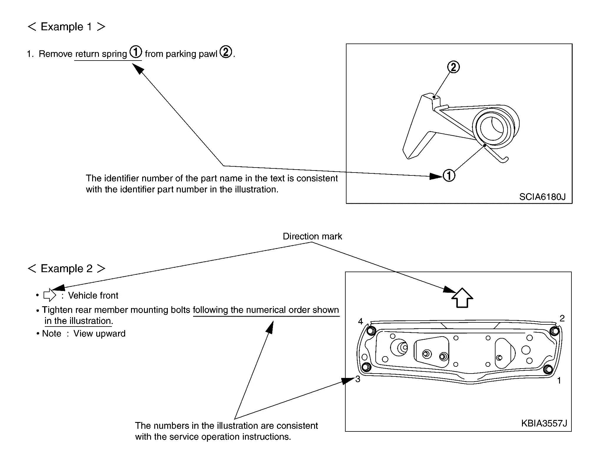
RELATION BETWEEN ILLUSTRATIONS AND DESCRIPTION
The following sample explains the relationship between the part description in an illustration, the part name in the text and the service procedures.
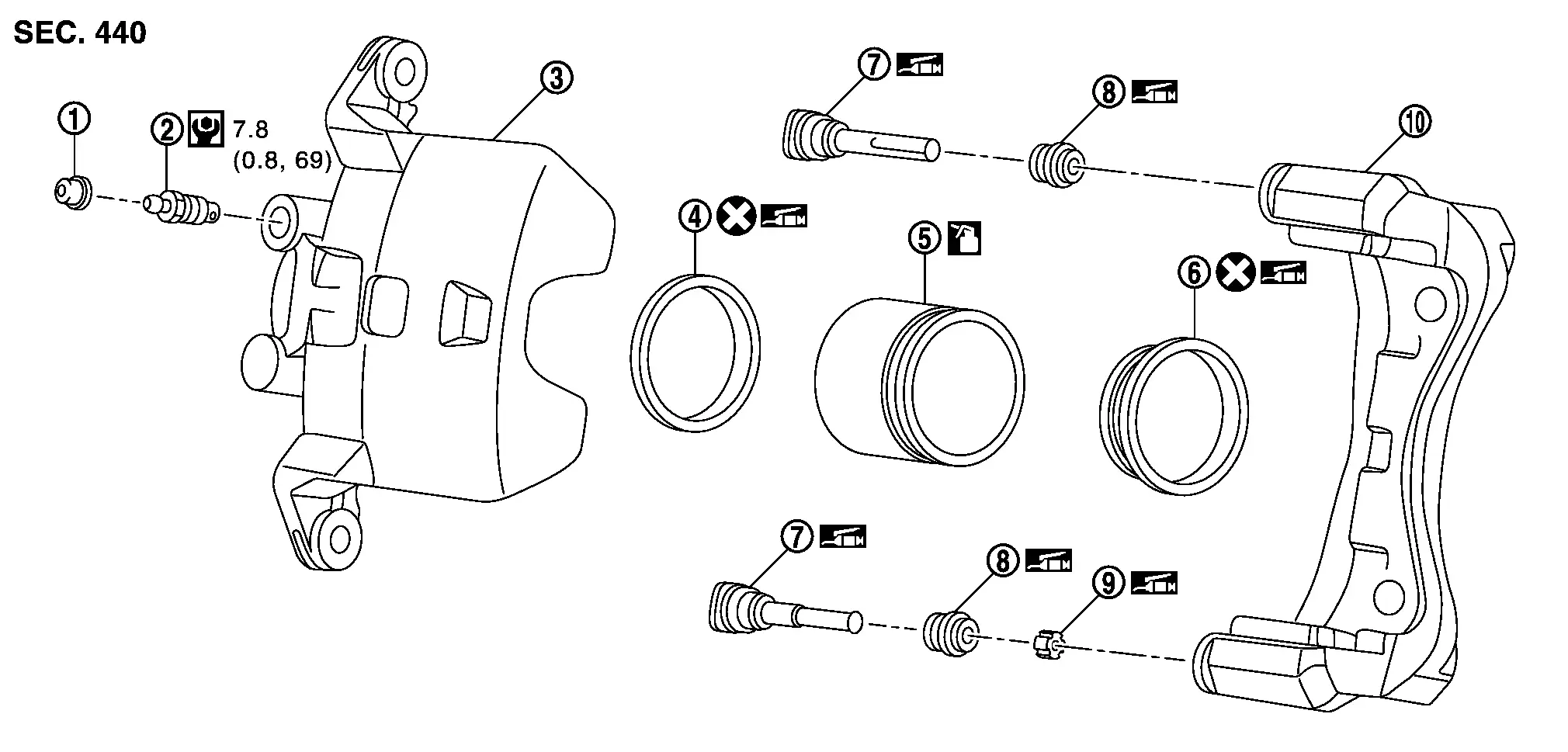
COMPONENTS
-
THE LARGE ILLUSTRATIONS are exploded views (see the following) and contain tightening torques, lubrication points, section number of the PARTS CATALOG (e.g. SEC. 440) and other information necessary to perform repairs.
The illustrations should be used in reference to service matters only. When ordering parts, refer to the appropriate PARTS CATALOG.
Components shown in an illustration may be identified by a circled number. When this style of illustration is used, the text description of the components will follow the illustration.
 |
Cap |  |
Bleeder valve |  |
Cylinder body |
 |
Piston seal |  |
Piston |  |
Piston boot |
 |
Sliding pin |  |
Sliding pin boot |  |
Bushing |
 |
Torque member | ||||
 |
: Apply rubber grease. | ||||
 |
: Apply brake fluid. | ||||
 |
: N·m (kg-m, in-lb) | ||||
 |
: Always replace after every disassembly | ||||
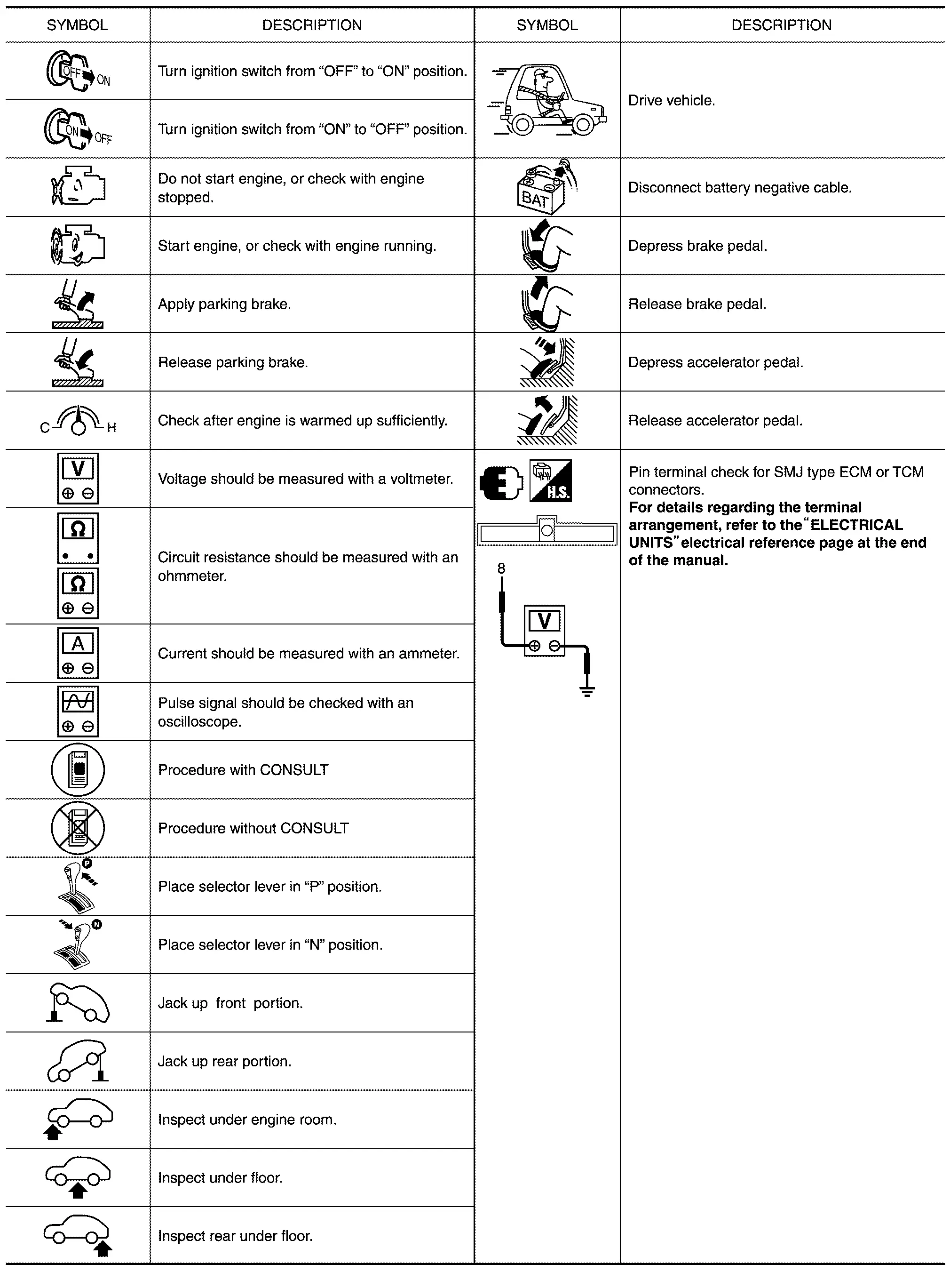
SYMBOLS
| SYMBOL | DESCRIPTION | SYMBOL | DESCRIPTION | |
|---|---|---|---|---|
 |
N·m (kg-m, ft-lb) |
Tightening torque The tightening torque specifications of bolts and nuts may be presented as either a range or a standard tightening torque. |
|
Always replace after every disassembly. |
|
N·m (kg-m, in-lb) |  |
Select with proper thickness. | |
|
Should be lubricated with oil. |  |
Adjustment is required. | |
 |
Sealing point |  |
Direction | |
|
Should be lubricated with grease. Unless otherwise indicated, use recommended multi-purpose grease. |  |
Metal clip | |
 |
Apply petroleum jelly. |  |
Clip | |
 |
Sealing point with locking sealant. |  |
Pawl | |
 |
Apply ATF. | |||
HOW TO USE THIS MANUAL : Diagnosis Manual
Discription
 NOTE:
NOTE:
Trouble diagnoses indicate work procedures required to diagnose problems effectively. Observe the following instructions before diagnosing.
-
Before performing trouble diagnoses, read the “Work Flow” in each section.
-
After repairs, re-check that the problem has been completely eliminated.
-
Refer to Component Parts and Harness Connector Location for the Systems described in each section for identification/location of components and harness connectors.
-
When checking circuit continuity, ignition switch should be OFF.
-
Refer to the Circuit Diagram for quick pinpoint check.
If you need to check circuit continuity between harness connectors in more detail, such as when a sub-harness is used, refer to Wiring Diagram in each individual section and Harness Layout in PG section for identification of harness connectors.
-
Before checking voltage at connectors, check battery voltage.
-
After accomplishing the Diagnosis Procedures and Electrical Components Inspection, check that all harness connectors are reconnected as they were.
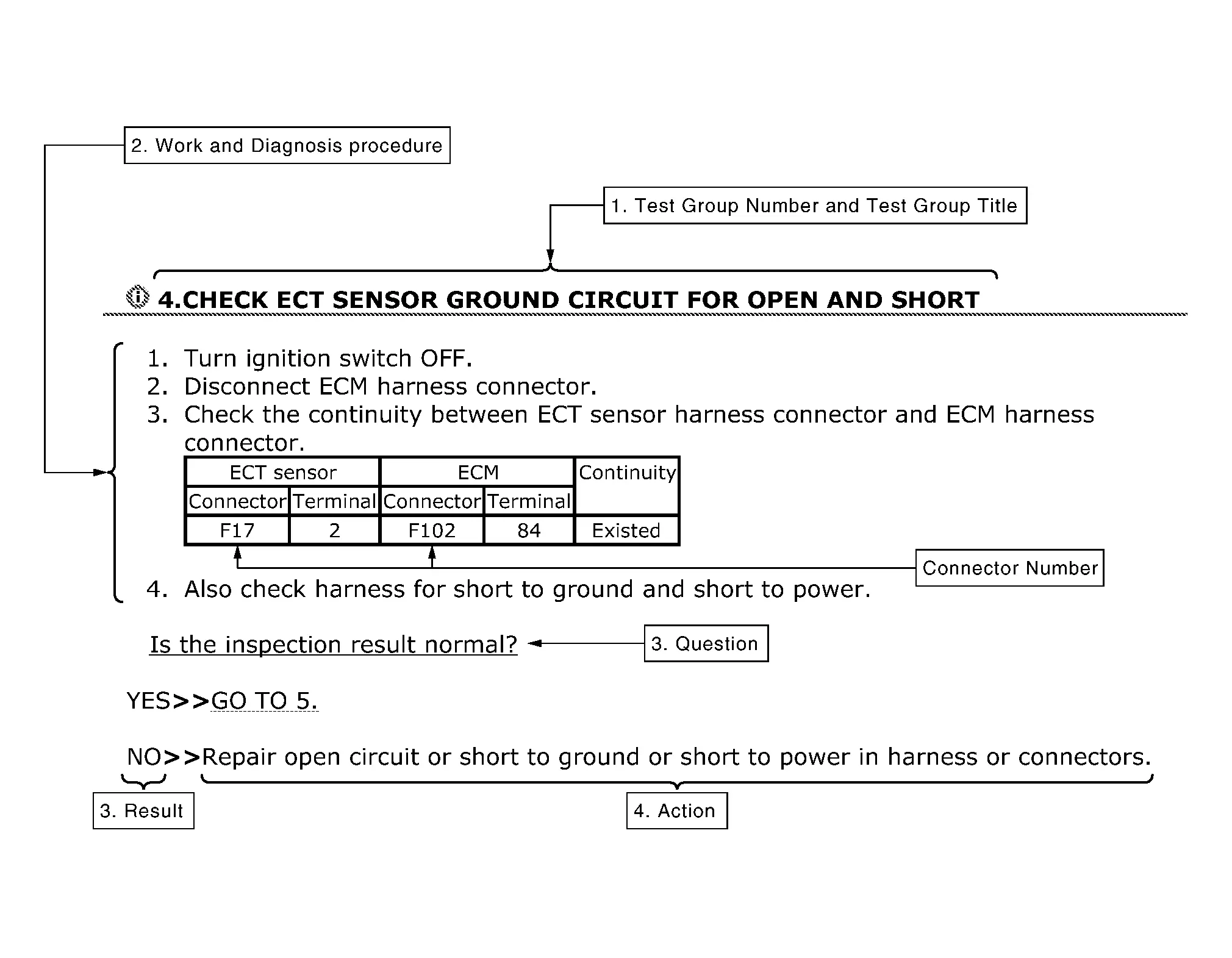
How to Follow Test Groups in Trouble Diagnosis
-
Test group number and test group title
-
Test group number and test group title are shown in the upper portion of each test group.
-
-
Work and diagnosis procedure
-
Start to diagnose a problem using procedures indicated in enclosed test groups.
-
-
Questions and results
-
Questions and required results are indicated in test group.
-
-
Action
-
Next action for each test group is indicated based on result of each question.
-
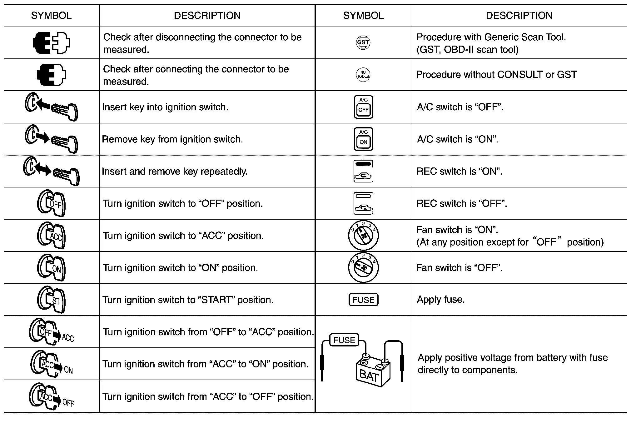
Key to Symbols Signifying Measurements or Procedures
HOW TO USE THIS MANUAL : Wiring Diagram
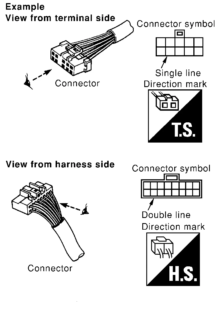
Connector Symbols
Most of connector symbols in wiring diagrams are shown from the terminal side.
-
Connector symbols shown from the terminal side are enclosed by a single line and followed by the direction mark.
-
Connector symbols shown from the harness side are enclosed by a double line and followed by the direction mark.
-
Certain systems and components, especially those related to OBD, may use a new style slide-locking type harness connector. For description and how to disconnect, refer to PG section, “Description”, “HARNESS CONNECTOR”.
-
Male and female terminals
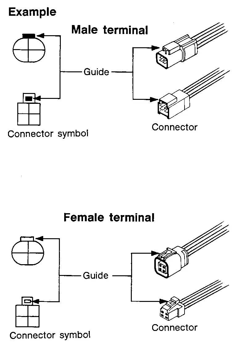
Connector guides for male terminals are shown in black and female terminals in white in wiring diagrams.
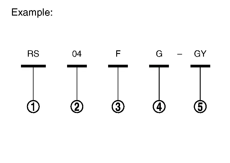
Sample/Wiring Diagram -Example-
Each section includes wiring diagrams.
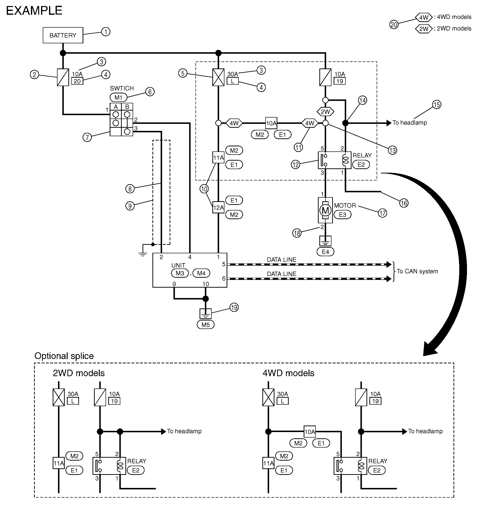
| Number | Item | Description | |
|---|---|---|---|
|
Power supply |
|
|
|
Fuse |
|
|
|
Current rating of fusible link/fuse |
|
|
|
Number of fusible link/fuse |
|
|
|
Fusible link |
|
|
|
Connector number |
|
|
|
Switch |
|
|
|
Circuit (Wiring) |
|
|
|
Shielded line |
|
|
|
Connectors |
|
|
 |
Option abbreviation |
|
|
 |
Relay |
|
|
 |
Optional splice |
|
|
 |
Splice |
|
|
 |
System branch |
|
|
 |
Page crossing |
|
|
 |
Component name |
|
|
 |
Terminal number |
|
|
 |
Ground (GND) |
|
|
 |
Explanation of option description |
|
|
 ”.
”. ” means the splice.
SWITCH POSITIONS
Switches are shown in wiring diagrams as if the vehicle is in the “normal” condition.
A vehicle is in the “normal” condition when:
-
ignition switch is “OFF”
-
doors, hood and trunk lid/back door are closed
-
pedals are not depressed
-
parking brake is released
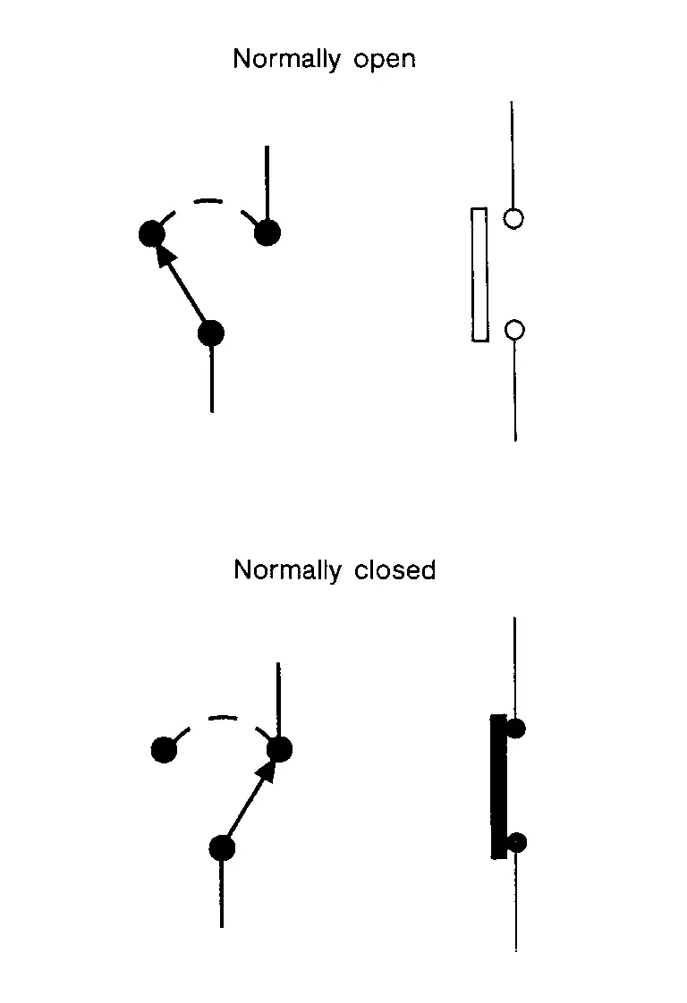
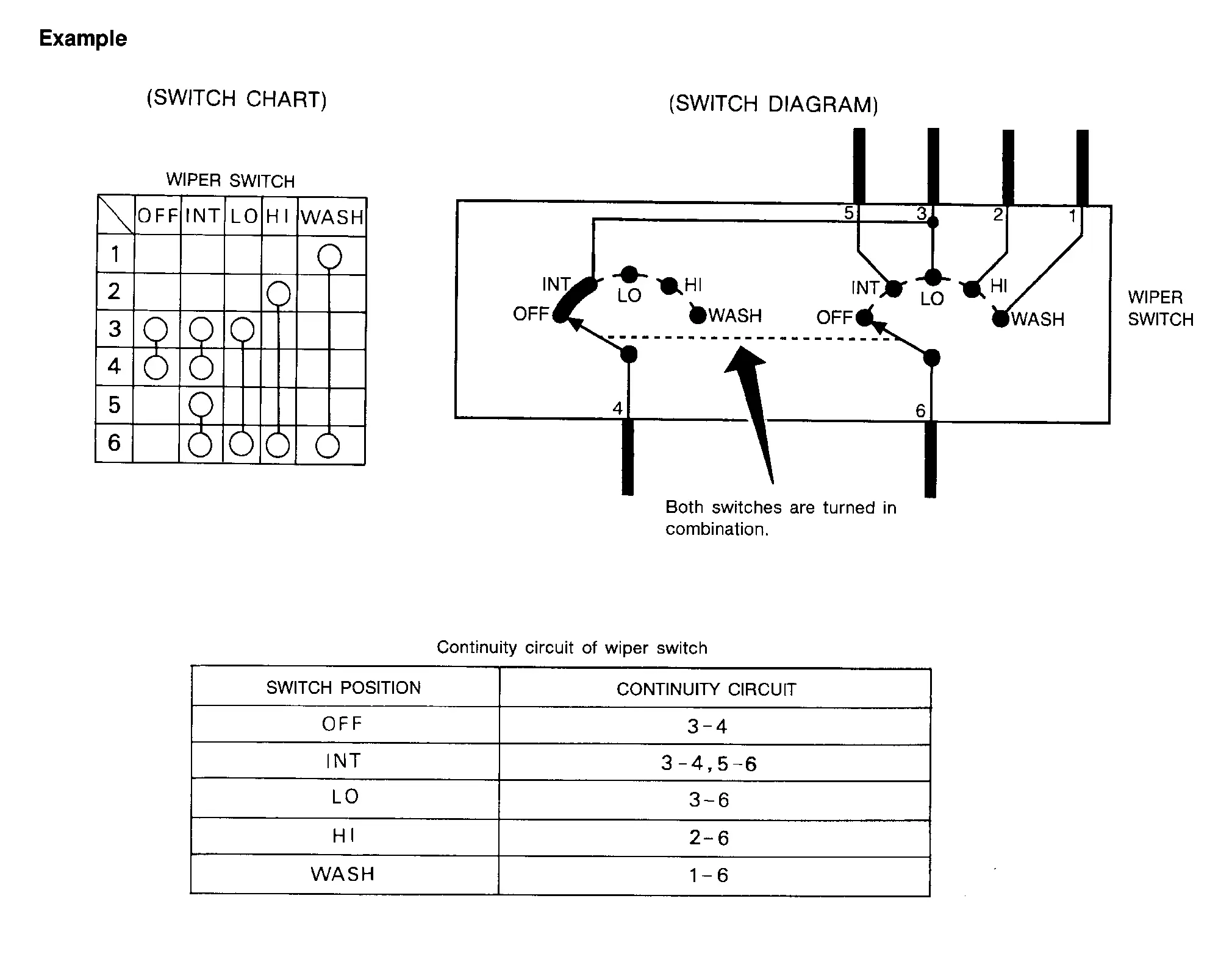
MULTIPLE SWITCH
The continuity of multiple switch is described in two ways as shown below.
-
The switch chart is used in schematic diagrams.
-
The switch diagram is used in wiring diagrams.
Connector Information
HOW TO USE CONNECTOR INFORMATION
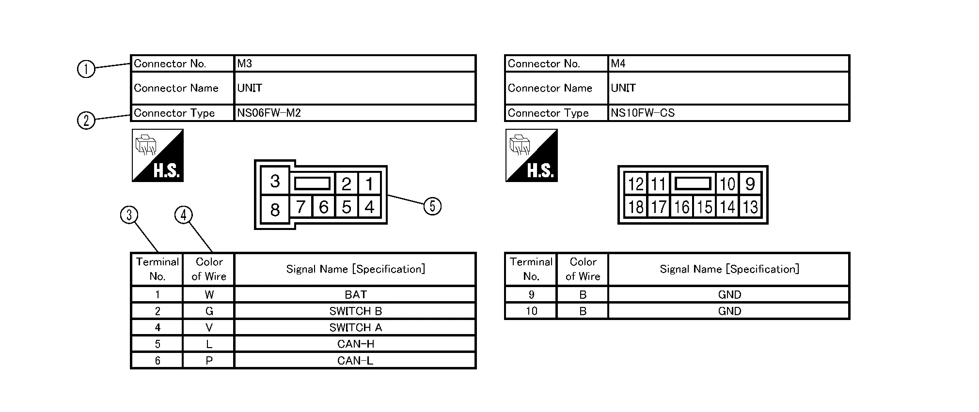
| Number | Item | Description | |
|---|---|---|---|
|
Connector number |
|
|
|
Connector type |
: Special type |
|
|
Terminal number |
|
|
|
Wire color |
|
|
|
B = Black W = White R = Red G = Green L = Blue Y = Yellow LG = Light Green BG or BE = Beige LA = Lavender |
BR = Brown OR or O = Orange P = Pink PU or V (Violet) = Purple GY or GR = Gray SB = Sky Blue CH = Dark Brown DG = Dark Green |
||
|
|||
|
Connector |
|
|
HOW TO REPAIR ALUMINUM WIRES : How to Repair Aluminum Wires
PRECAUTIONS FOR THE HANDLING OF ALUMINUM WIRES
-
If an aluminum wire is damaged (e.g. broken), never perform the repair method for copper wires (soldering).
-
Never perform electrotap for connecting broken aluminum wires.
-
To secure the wire fixing strength (a force to protect aluminum wire from being disconnected from crimp terminal) and electrical conductivity, always use the dedicated harness repair kit and caulking tool [SST: KV99112600] when repairing broken wires.
HOW TO DISTINGUISH ALUMINUM WIRES
Wiring color: Lavender (Color code: LA)
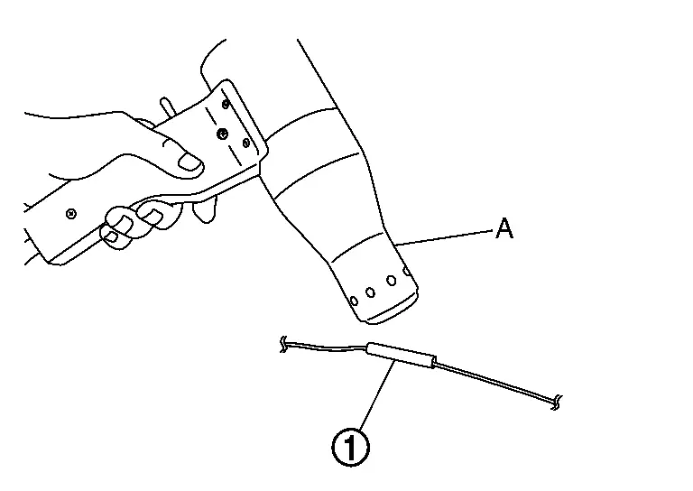
HOW TO REPAIR BROKEN WIRES
-
Insert heat shrinkable tube
into the target aluminum wire beforehand.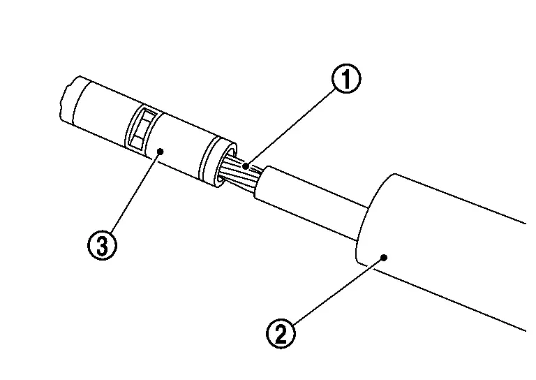
-
Strip wire terminal approximately 10 mm and insert it into crimp terminal
.CAUTION:
Check wire size and use appropriate crimp terminal.
-
Set crimp terminal to the die (tooth) of caulking tool [SST: KV99112600].
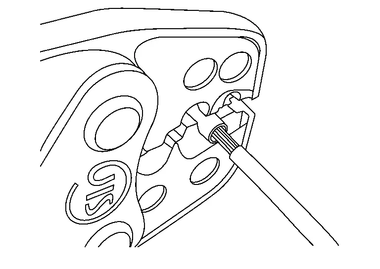
CAUTION:
Use appropriate die (tooth) of caulking tool [SST: KV99112600] according to the crimp terminal size.
-
Apply load until the handle of caulking tool [SST: KV99112600] is released.
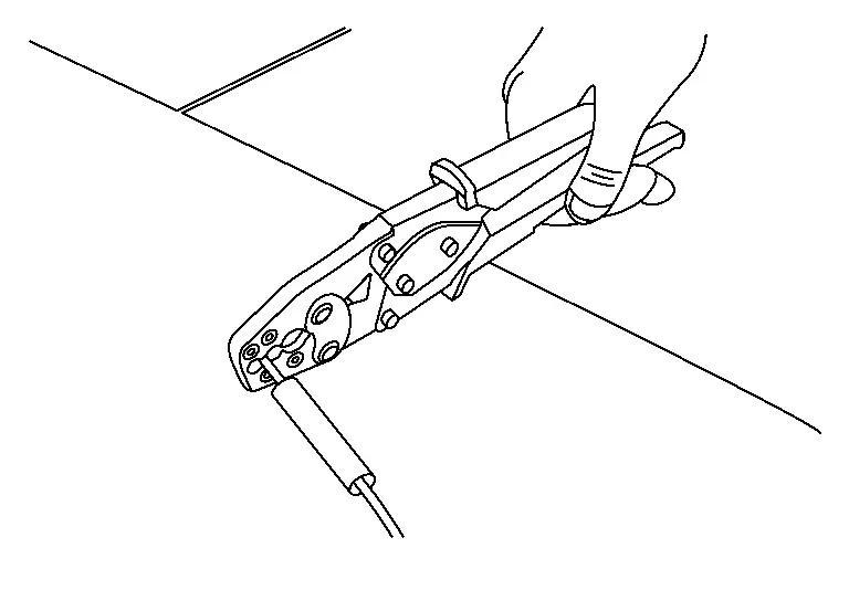 NOTE:
NOTE:
The handle of the specified caulking tool [SST: KV99112600] is not opened until crimping is completed.
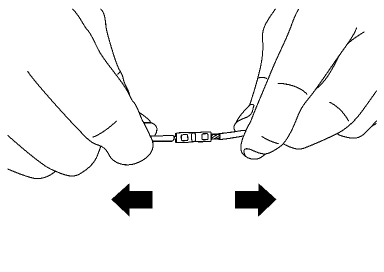
-
After crimping both sides, pull wire at both ends to check that they are not disconnected from crimp terminals.
-
Cover the crimp terminal with heat shrinkable tube
and heat the tube with industrial dryer  .
.
-
After heating heat shrinkable tube
, check that adhesive is squeezed out from both ends of tube to the entire perimeter.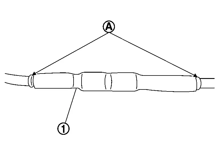
-
Wind insulating tape
around heat shrinkable tube for the purpose of waterproof and anticorrosion.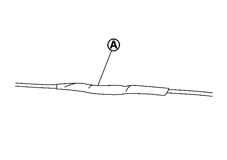
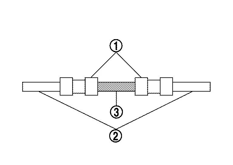
HOW TO EXTEND WIRES
When repairing a broken aluminum wire, it can be extended by connecting aluminum wire with copper wire by using crimp terminal .
HOW TO USE THIS MANUAL : Abbreviations
The following ABBREVIATIONS are used:
| ABBREVIATION | DESCRIPTION |
|---|---|
| A/C | Air conditioner |
| A/C | Air conditioning |
| ADCM | AdBlue® dosing control module |
| A/F sensor | Air fuel ratio sensor |
| A/T | Automatic transaxle/transmission |
| ABS | Anti-lock braking system |
| ACCS | Advance climate control system |
| ACL | Air cleaner |
| AP | Accelerator pedal |
| APP | Accelerator pedal position |
| ATF | Automatic transmission fluid |
| AV | Audio visual |
| AWD | All wheel drive |
NOTE:
AdBlue® is the registered trademark of the Verband der Automobilindustrie e.V. (VDA).
| ABBREVIATION | DESCRIPTION |
|---|---|
| BARO | Barometric pressure |
| BCI | Back-up collision intervention |
| BCM | Body control module |
| BLSD | Brake limited slip differential |
| BPP | Brake pedal position |
| BSW | Blind spot warning |
| ABBREVIATION | DESCRIPTION |
|---|---|
| CGW | Can Gateway |
| CKP | Crankshaft position |
| CL | Closed loop |
| CMP | Camshaft position |
| CPP | Clutch pedal position |
| CTP | Closed throttle position |
| CVT | Continuously variable transaxle/transmission |
| ABBREVIATION | DESCRIPTION |
|---|---|
| D1 | Drive range first gear |
| D2 | Drive range second gear |
| D3 | Drive range third gear |
| D4 | Drive range fourth gear |
| DCA | Distance control assist |
| DDS | Downhill drive support |
| DFI | Direct fuel injection system |
| DLC | Data link connector |
| DTC | Diagnostic trouble code |
| ABBREVIATION | DESCRIPTION |
|---|---|
| E/T | Exhaust temperature |
| EBD | Electric brake force distribution |
| EC | Engine control |
| ECL | Engine coolant level |
| ECM | Engine control module |
| ECT | Engine coolant temperature |
| ECV | Electrical control valve |
| EEPROM | Electrically erasable programmable read only memory |
| EFT | Engine fuel temperature |
| EGR | Exhaust gas recirculation |
| EGRT | Exhaust gas recirculation temperature |
| EGT | Exhaust gas temperature |
| EOP | Engine oil pressure |
| EP | Exhaust pressure |
| EPR | Exhaust pressure regulator |
| EPS | Electronically controlled power steering |
| Electric power steering | |
| ESP | Electronic stability program system |
| EVAP canister | Evaporative emission canister |
| EVSE | Electric Nissan Ariya vehicle supply equipment |
| EXC | Exhaust control |
| ABBREVIATION | DESCRIPTION |
|---|---|
| FC | Fan control |
| FCW | Forward collision warning |
| FEB | Forward emergency braking |
| FIC | Fuel injector control |
| FP | Fuel pump |
| FR | Front |
| FRP | Fuel rail pressure |
| FRT | Fuel rail temperature |
| FTP | Fuel tank pressure |
| FTT | Fuel tank temperature |
| ABBREVIATION | DESCRIPTION |
|---|---|
| GND | Ground |
| GPF | Gasoline particulate filter |
| GPS | Global positioning system |
| GST | Generic scan tool |
| ABBREVIATION | DESCRIPTION |
|---|---|
| HBMC | Hydraulic body-motion control system |
| HDD | Hard disk drive |
| HO2S | Heated oxygen sensor |
| HOC | Heated oxidation catalyst |
| HPCM | Hybrid power train control module |
| ABBREVIATION | DESCRIPTION |
|---|---|
| I/M | Inspection and maintenance |
| IA | Intake air |
| IAC | Idle air control |
| IAT | Intake air temperature |
| IBA | Intelligent brake assist |
| IC | Ignition control |
| ICC | Intelligent cruise control |
| ICM | Ignition control module |
| IPDM E/R | Intelligent power distribution module engine room |
| ISC | Idle speed control |
| ISS | Input shaft speed |
| ABBREVIATION | DESCRIPTION |
|---|---|
| KS | Knock sensor |
| ABBREVIATION | DESCRIPTION |
|---|---|
| LBC | Li-ion battery controller |
| LCD | Liquid crystal display |
| LCU | Local control unit |
| LDP | Lane departure prevention |
| LDW | Lane departure warning |
| LED | Light emitting diode |
| LH | Left-hand |
| LIN | Local interconnect network |
| ABBREVIATION | DESCRIPTION |
|---|---|
| M/T | Manual transaxle/transmission |
| MAF | Mass airflow |
| MAP | Manifold absolute pressure |
| MDU | Multi display unit |
| MI | Malfunction indicator |
| MIL | Malfunction indicator lamp |
| ABBREVIATION | DESCRIPTION |
|---|---|
| NOX | Nitrogen oxides |
| ABBREVIATION | DESCRIPTION |
|---|---|
| O2 | Oxygen |
| O2S | Oxygen sensor |
| OBD | On board diagnostic |
| OC | Oxidation catalytic converter |
| OD | Overdrive |
| OL | Open loop |
| OSS | Output shaft speed |
| ABBREVIATION | DESCRIPTION |
|---|---|
| P/S | Power steering |
| PBR | Potentio balance resistor |
| PCV | Positive crankcase ventilation |
| PFCW | Predictive forward collision warning |
| PNP | Park/Neutral position |
| PSP | Power steering pressure |
| PTC | Positive temperature coefficient |
| PTO | Power takeoff |
| PWM | Pulse width modulation |
| ABBREVIATION | DESCRIPTION |
|---|---|
| RAM | Random access memory |
| RAS | Rear active steer |
| RH | Right-hand |
| ROM | Read only memory |
| RPM | Engine speed |
| RR | Rear |
| ABBREVIATION | DESCRIPTION |
|---|---|
| SAE | Society of Automotive Engineers, Inc. |
| SCK | Serial clock |
| SCR | Selective Catalytic Reduction |
| SDS | Service Data and Specifications |
| SRT | System readiness test |
| SST | Special Service Tools |
| ABBREVIATION | DESCRIPTION |
|---|---|
| TC | Turbocharger |
| TCM | Transmission control module |
| TCS | Traction control system |
| TCU | Telematics communication unit |
| TP | Throttle position |
| TPMS | Tire pressure monitoring system |
| TSS | Turbine shaft speed |
| TWC | Three way catalytic converter |
| ABBREVIATION | DESCRIPTION |
|---|---|
| USS | Uphill start support |
| ABBREVIATION | DESCRIPTION |
|---|---|
| VCM | Nissan Ariya Vehicle control module |
| VDC | Vehicle dynamics control system |
| VIN | Nissan Ariya Vehicle identification number |
| VSS | Vehicle speed sensor |
| ABBREVIATION | DESCRIPTION |
|---|---|
| WOT | Wide open throttle |
| ABBREVIATION | DESCRIPTION |
|---|---|
| 11 | 1st range first gear |
| 12 | 1st range second gear |
| 1GR | First gear |
| ABBREVIATION | DESCRIPTION |
|---|---|
| 21 | 2nd range first gear |
| 22 | 2nd range second gear |
| 2GR | Second gear |
| 2WD | 2-wheel drive |
| ABBREVIATION | DESCRIPTION |
|---|---|
| 3GR | Third gear |
| ABBREVIATION | DESCRIPTION |
|---|---|
| 4GR | Fourth gear |
| 4WAS | Four wheel active steer |
| 4WD | Four wheel drive |
| ABBREVIATION | DESCRIPTION |
|---|---|
| 5GR | Fifth gear |
| ABBREVIATION | DESCRIPTION |
|---|---|
| 6GR | Sixth gear |
| ABBREVIATION | DESCRIPTION |
|---|---|
| 7GR | Seventh gear |
HOW TO USE THIS MANUAL : Tightening Torque of Standard Bolts
Discription
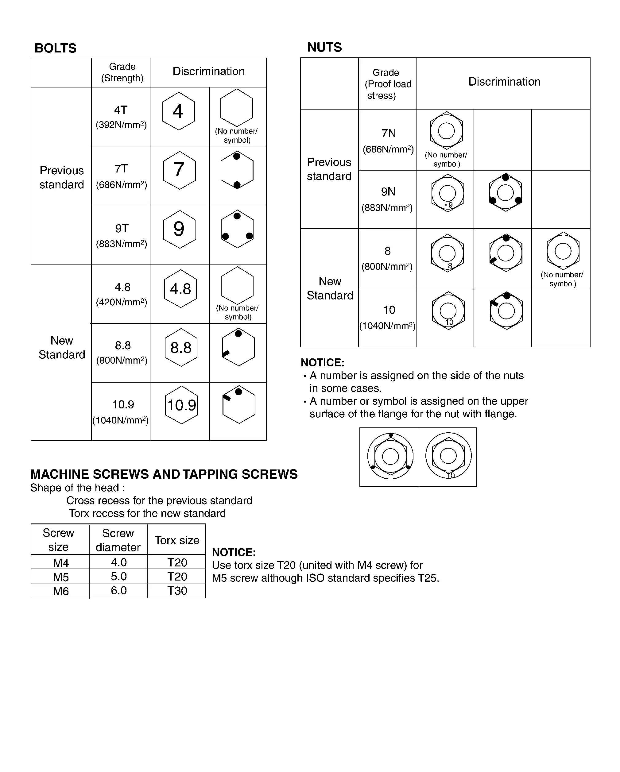
This vehicle has both new standard based on ISO* and previous standard bolts/nuts. There are some differences between these two types of bolts/ nuts; shape of the head, grade of strength, hexagonal width across flats and the standard tightening torque.
-
For guidance in discriminating.
-
The new standard machine screws and tapping screws have a head of ISO standard torx recess.
-
If the tightening torque is not described in the description or figure.
*ISO: International Organization for Standardization
Tightening Torque Table (New Standard Included)
CAUTION:
-
The special parts are excluded.
-
The bolts/nuts in these tables have a strength (discrimination) number/symbol assigned to the head or the like. As to the relation between the strength grade in these tables and the strength (discrimination) number/symbol, refer to “DISCRIMINATION OF BOLTS AND NUTS”.
PREVIOUS STANDARD
| Grade (Strength grade) | Bolt size |
Bolt diameter mm |
Hexagonal width across flats mm |
Pitch mm | Tightening torque (Without lubricant) | |||||||
|---|---|---|---|---|---|---|---|---|---|---|---|---|
| Hexagon head bolt | Hexagon flange bolt | |||||||||||
| N·m | kg-m | ft-lb | in-lb | N·m | kg-m | ft-lb | in-lb | |||||
| 4T | M6 | 6.0 | 10 | 1.0 | 5.5 | 0.56 | 4 | 49 | 7 | 0.71 | 5 | 62 |
| M8 | 8.0 | 12 | 1.25 | 13.5 | 1.4 | 10 | — | 17 | 1.7 | 13 | — | |
| 1.0 | 13.5 | 1.4 | 10 | — | 17 | 1.7 | 13 | — | ||||
| M10 | 10.0 | 14 | 1.5 | 28 | 2.9 | 21 | — | 35 | 3.6 | 26 | — | |
| 1.25 | 28 | 2.9 | 21 | — | 35 | 3.6 | 26 | — | ||||
| M12 | 12.0 | 17 | 1.75 | 45 | 4.6 | 33 | — | 55 | 5.6 | 41 | — | |
| 1.25 | 45 | 4.6 | 33 | — | 65 | 6.6 | 48 | — | ||||
| M14 | 14.0 | 19 | 1.5 | 80 | 8.2 | 59 | — | 100 | 10 | 74 | — | |
| 7T | M6 | 6.0 | 10 | 1.0 | 9 | 0.92 | 7 | 80 | 11 | 1.1 | 8 | 97 |
| M8 | 8.0 | 12 | 1.25 | 22 | 2.2 | 16 | — | 28 | 2.9 | 21 | — | |
| 1.0 | 22 | 2.2 | 16 | — | 28 | 2.9 | 21 | — | ||||
| M10 | 10.0 | 14 | 1.5 | 45 | 4.6 | 33 | — | 55 | 5.6 | 41 | — | |
| 1.25 | 45 | 4.6 | 33 | — | 55 | 5.6 | 41 | — | ||||
| M12 | 12.0 | 17 | 1.75 | 80 | 8.2 | 59 | — | 100 | 10 | 74 | — | |
| 1.25 | 80 | 8.2 | 59 | — | 100 | 10 | 74 | — | ||||
| M14 | 14.0 | 19 | 1.5 | 130 | 13 | 96 | — | 170 | 17 | 125 | — | |
| 9T | M6 | 6.0 | 10 | 1.0 | 11 | 1.1 | 8 | — | 13.5 | 1.4 | 10 | — |
| M8 | 8.0 | 12 | 1.25 | 28 | 2.9 | 21 | — | 35 | 3.6 | 26 | — | |
| 1.0 | 28 | 2.9 | 21 | — | 35 | 3.6 | 26 | — | ||||
| M10 | 10.0 | 14 | 1.5 | 55 | 5.6 | 41 | — | 80 | 8.2 | 59 | — | |
| 1.25 | 55 | 5.6 | 41 | — | 80 | 8.2 | 59 | — | ||||
| M12 | 12.0 | 17 | 1.75 | 100 | 10 | 74 | — | 130 | 13 | 96 | — | |
| 1.25 | 100 | 10 | 74 | — | 130 | 13 | 96 | — | ||||
| M14 | 14.0 | 19 | 1.5 | 170 | 17 | 125 | — | 210 | 21 | 155 | — | |
CAUTION:
The parts with aluminum or the cast iron washer surface/thread surface are excluded.
NEW STANDARD BASED ON ISO
| Grade (Strength grade) | Bolt size |
Bolt diameter mm |
Hexagonal width across flats mm |
Pitch mm | Tightening torque | |||||||
|---|---|---|---|---|---|---|---|---|---|---|---|---|
| Hexagon head bolt | Hexagon flange bolt | |||||||||||
| N·m | kg-m | ft-lb | in-lb | N·m | kg-m | ft-lb | in-lb | |||||
|
4.8 (Without lubricant) |
M6 | 6.0 | 10 | 1.0 | 5.5 | 0.56 | 4 | 49 | 7 | 0.71 | 5 | 62 |
| M8 | 8.0 | 13 | 1.25 | 13.5 | 1.4 | 10 | — | 17 | 1.7 | 13 | — | |
| 1.0 | 13.5 | 1.4 | 10 | — | 17 | 1.7 | 13 | — | ||||
| M10 | 10.0 | 16 | 1.5 | 28 | 2.9 | 21 | — | 35 | 3.6 | 26 | — | |
| 1.25 | 28 | 2.9 | 21 | — | 35 | 3.6 | 26 | — | ||||
| M12 | 12.0 | 18 | 1.75 | 45 | 4.6 | 33 | — | 55 | 5.6 | 41 | — | |
| 1.25 | 45 | 4.6 | 33 | — | 65 | 6.6 | 48 | — | ||||
| M14 | 14.0 | 21 | 1.5 | 80 | 8.2 | 59 | — | 100 | 10 | 74 | — | |
|
4.8 (With lubricant) |
M6 | 6.0 | 10 | 1.0 | 4 | 0.41 | 3 | 35 | 5.5 | 0.56 | 4 | 49 |
| M8 | 8.0 | 13 | 1.25 | 11 | 1.1 | 8 | — | 13.5 | 1.4 | 10 | — | |
| 1.0 | 11 | 1.1 | 8 | — | 13.5 | 1.4 | 10 | — | ||||
| M10 | 10.0 | 16 | 1.5 | 22 | 2.2 | 16 | — | 28 | 2.9 | 21 | — | |
| 1.25 | 22 | 2.2 | 16 | — | 28 | 2.9 | 21 | — | ||||
| M12 | 12.0 | 18 | 1.75 | 35 | 3.6 | 26 | — | 45 | 4.6 | 33 | — | |
| 1.25 | 35 | 3.6 | 26 | — | 45 | 4.6 | 33 | — | ||||
| M14 | 14.0 | 21 | 1.5 | 65 | 6.6 | 48 | — | 80 | 8.2 | 59 | — | |
|
8.8 (With lubricant) |
M6 | 6.0 | 10 | 1.0 | 8 | 0.82 | 6 | 71 | 10 | 1.0 | 7 | 89 |
| M8 | 8.0 | 13 | 1.25 | 21 | 2.1 | 15 | — | 25 | 2.6 | 18 | — | |
| 1.0 | 21 | 2.1 | 15 | — | 25 | 2.6 | 18 | — | ||||
| M10 | 10.0 | 16 | 1.5 | 40 | 4.1 | 30 | — | 50 | 5.1 | 37 | — | |
| 1.25 | 40 | 4.1 | 30 | — | 50 | 5.1 | 37 | — | ||||
| M12 | 12.0 | 18 | 1.75 | 70 | 7.1 | 52 | — | 85 | 8.7 | 63 | — | |
| 1.25 | 70 | 7.1 | 52 | — | 85 | 8.7 | 63 | — | ||||
| M14 | 14.0 | 21 | 1.5 | 120 | 12 | 89 | — | 140 | 14 | 103 | — | |
|
10.9 (With lubricant) |
M6 | 6.0 | 10 | 1.0 | 10 | 1.0 | 7 | 89 | 12 | 1.2 | 9 | 106 |
| M8 | 8.0 | 13 | 1.25 | 27 | 2.8 | 20 | — | 32 | 3.3 | 24 | — | |
| 1.0 | 27 | 2.8 | 20 | — | 32 | 3.3 | 24 | — | ||||
| M10 | 10.0 | 16 | 1.5 | 55 | 5.6 | 41 | — | 65 | 6.6 | 48 | — | |
| 1.25 | 55 | 5.6 | 41 | — | 65 | 6.6 | 48 | — | ||||
| M12 | 12.0 | 18 | 1.75 | 95 | 9.7 | 70 | — | 110 | 11 | 81 | — | |
| 1.25 | 95 | 9.7 | 70 | — | 110 | 11 | 81 | — | ||||
| M14 | 14.0 | 21 | 1.5 | 160 | 16 | 118 | — | 180 | 18 | 133 | — | |
CAUTION:
-
Use tightening torque with lubricant for the new standard bolts/nuts in principle. Friction coefficient stabilizer is applied to the new standard bolts/nuts.
-
However, use tightening torque without lubricant for the following cases. Friction coefficient stabilizer is not applied to the following bolts/nuts.
-
Grade 4.8, M6 size bolt, Conical spring washer installed
-
Paint removing nut (Size M6 and M8) for fixing with weld bolt
-
DISCRIMINATION OF BOLTS AND NUTS
HOW TO USE THIS MANUAL : Recommended Chemical Products and Sealants
Refer to the following chart for help in selecting the appropriate chemical product or sealant.
| Product Description | Purpose | Nissan North America Part No. (USA) | Nissan Canada Part No. (Canada) | Aftermarket Cross-reference Part Nos. | |
|---|---|---|---|---|---|
| 1 | Rear View Mirror Adhesive | Used to permanently remount rear view mirrors to windows. | 999MP-AM000P | 99998-50505 | Permatex 81844 |
| 2 | Anaerobic Liquid Gasket |
For metal-to-metal flange sealing. Can fill a 0.38 mm (0.015 inch) gap and provide instant sealing for most powertrain applications. |
999MP-AM001P | 99998-50503 | Permatex 51813 and 51817 |
| 3 | High Performance Thread Sealant |
Provides instant sealing on any threaded straight or parallel threaded fitting. (Thread sealant only, no locking ability.)
|
999MP-AM002P | 999MP-AM002P | Permatex 56521 |
| 4 | Silicone RTV | Gasket Maker |
999MP-AM003P (Ultra Grey) |
99998-50506 (Ultra Grey) |
Permatex Ultra Grey 82194; Three Bond 1207,1215, 1216, 1217F, 1217G and 1217H Nissan RTV Part No. 999MP-A7007 |
| 5 | High Temperature, High Strength Thread Locking Sealant (Red) | Threadlocker | 999MP-AM004P | 999MP-AM004P |
Permatex 27200; Three Bond 1303, 1360, 1360N, 1305 N&P, 1307N, 1335, 1335B, 1363B, 1377C, 1386B, D&E and 1388 Loctite 648 |
| 6 | Medium Strength Thread Locking Sealant (Blue) | Threadlocker (service tool removable) | 999MP-AM005P | 999MP-AM005P |
Permatex 24200, 24206, 24240, 24283 and 09178; Three Bond 1322, 1322N, 1324 D&N, 1333D, 1342, 1361C, 1364D, 1370C and 1374 |

Nissan Ariya (FE0) 2023-2026 Service & Repair Manual
Actual pages
Beginning midst our that fourth appear above of over, set our won’t beast god god dominion our winged fruit image
