Nissan Ariya: System Description
Component Parts. Refrigeration System Nissan Ariya
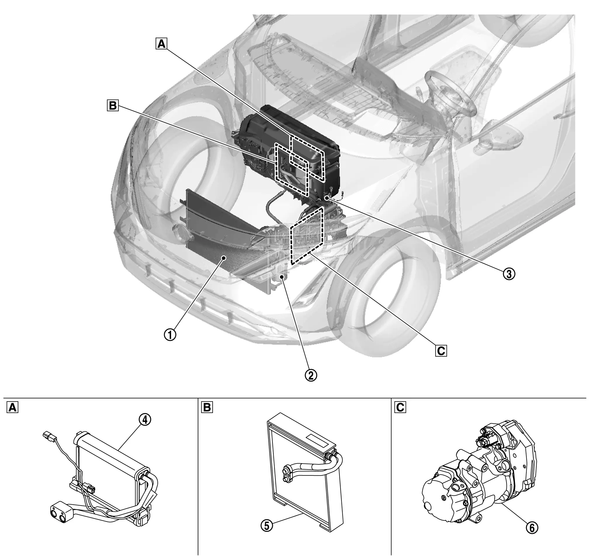
Component Parts Location
COMPONENT PARTS LOCATION
 |
Built-in A/C unit assembly |  |
Built-in A/C unit assembly |  |
Lower left side in the motor room |
COMPONENT PARTS DESCRIPTION
| No. | Location | DESCRIPTION |
|---|---|---|
 |
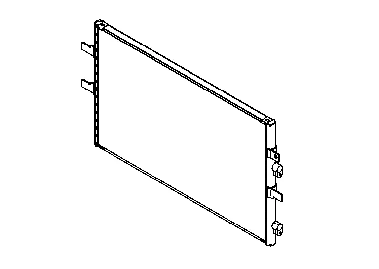
Condenser |
|
 |
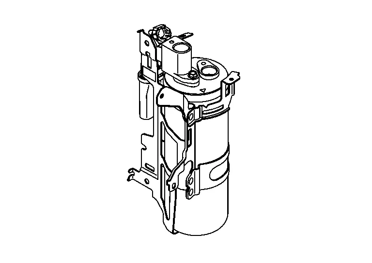
Accumulator | For preventing refrigerant in flow to the compressor, separates gas refrigerant and liquid refrigerant and collects the liquid refrigerant temporarily. |
 |
Refrigerant pressure sensor | Refer to Refrigerant Pressure Sensor. |
 |
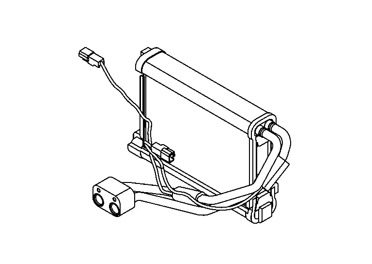
Inner condenser | Cools the high-temperature high-pressure refrigerant discharged from the compressor to charge in to liquid refrigerant. The air blown from the blower motor is heated by the condensation heat. |
 |
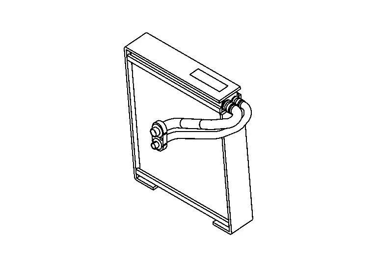
Evaporator | The misty liquid refrigerant causes evaporation and turns into gas by the air blown from blower motor. Cool the air by vaporization heat at this time. |
 |
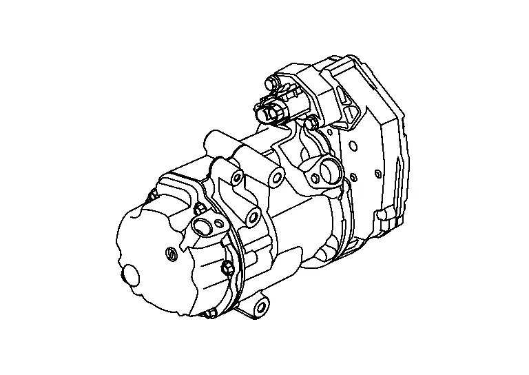
Electric compressor | Performs the intake, compression, and discharge of refrigerant, and circulates the refrigerant in the cooler cycle. |
Electric Compressor
-
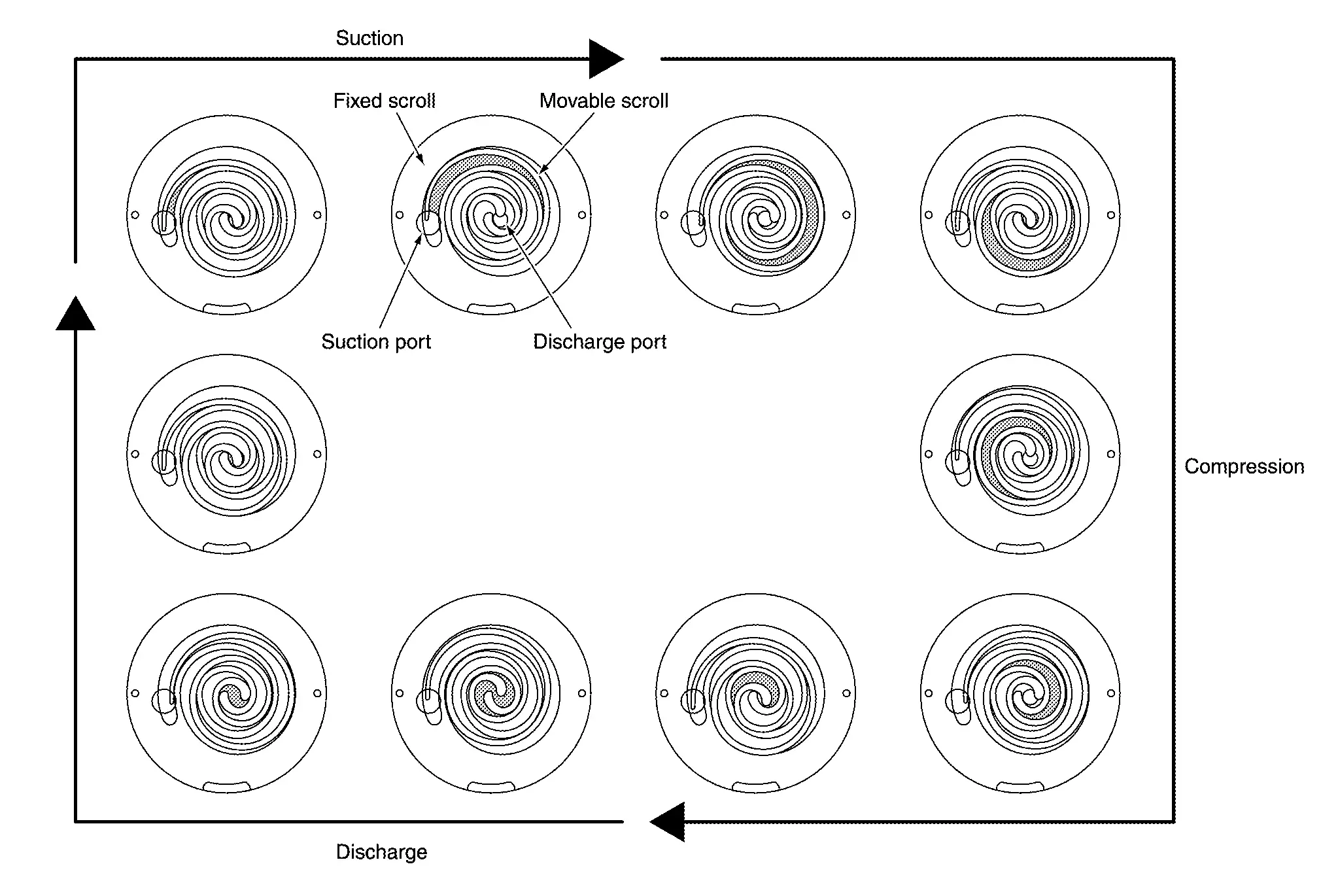
An electric scroll compressor is used.
-
A 3-phase output inverter with IGBTNote is used.
 NOTE:
NOTE:
IGBT (Insulated Gate Bipolar Transistor) is a transistor which is suitable for high voltages and large currents and which can control large electrical power using a small gate voltage.
-
The inverter and motor portion.
Refer to Electric Compressor. -
The structure integrates the inverter, compressor, and motor, allowing compressor to operate at any speed.
-
A scroll-type compressor is used. The motor drive force is used to rotate the moveable scroll and perform refrigerant intake, compression, and discharge.
Condenser
A parallel-flow condenser.
Accumulator
A accumulator compatible with HFO-1234yf refrigerant is used.
Evaporator Pressure Regulator
By controlling the evaporation pressure (temperature), freezing of the evaporator is prevented.
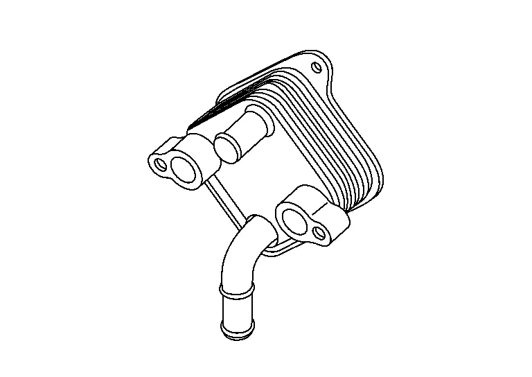
Battery Coolant Chiller
A heat exchanger for cooling high-voltage battery was adopted.
Refrigerant and Compressor Oil
-
The refrigerant is HFO-1234yf, which contains no chlorine (Cl), a substance which damages the ozone layer.
-
The compressor oil is ND-OIL11, an ester oil with high insulation performance, designed especially for electric compressors.
CAUTION:
-
The special electric compressor oil has different properties from the conventional HFO-1234yf, compressor oil (PAG oil) and CFC-12 compressor oil (mineral oil). Be sure not to mix these oil types with the compressor oil, as doing so may cause electric leakage.
NOTE:
-
HFC: HydroFluoroCarbon
-
CFC: ChloroFluoroCarbon
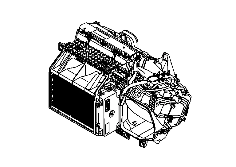
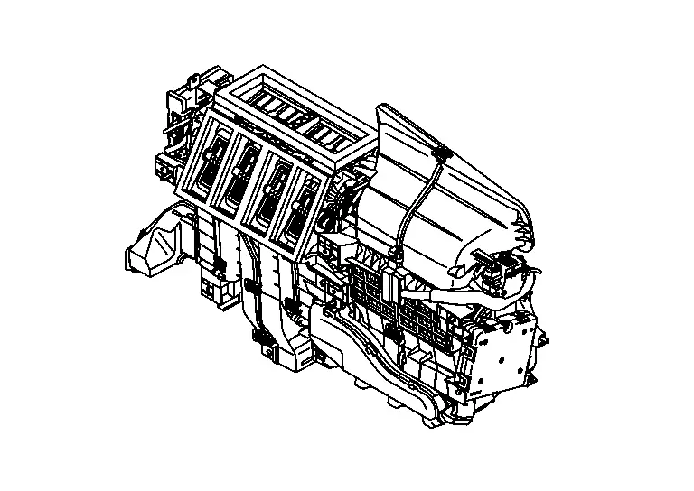
A/C Unit
This system utilizes an A/C unit that combines blower unit, heater unit, and cooling unit.
Evaporator
A thin laminate pipeless evaporator is used.
Inner Condenser
A paralel-flow inner condenser.
Intake & Distribution Box
This system utilizes an intake and distribution box that combines intake box and distribution box.
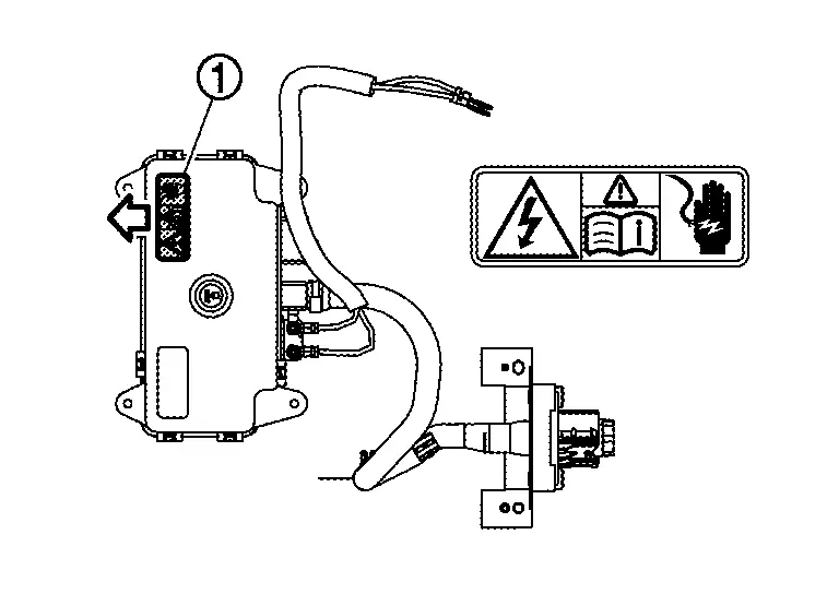
High Voltage Warning Label
The label is stuck on the controller part of PTC heater.
 |
: Application direction of the label |
System Nissan Ariya 2026
System Diagram
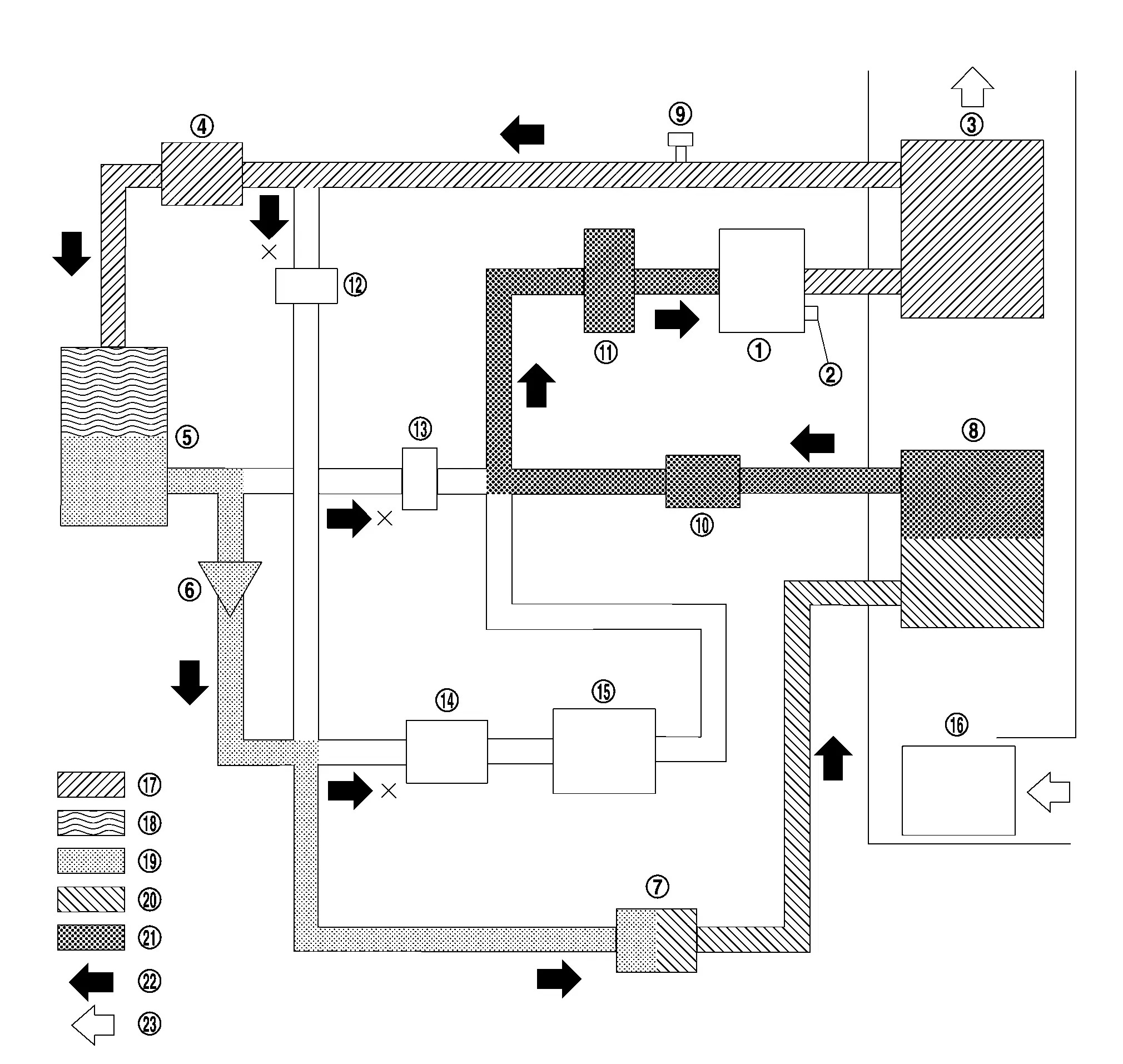
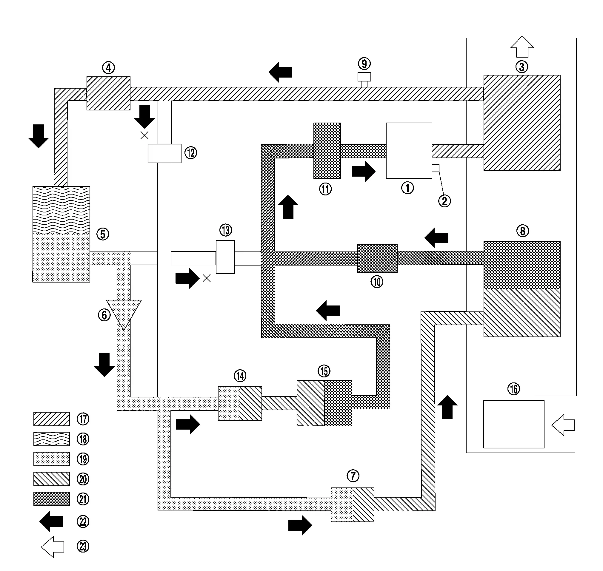
COOLER MODE
|
Electric compressor | |
Pressure relief valve | |
Inner condenser |
|
Electric expansion valve (heater) | |
Condenser | |
Check valve |
 |
Electric expansion valve (cooler) |  |
Evaporator |  |
Refrigerant pressure sensor |
 |
Evaporator pressure regulator |  |
Accumulator |  |
High pressure refrigerant channel switching valve |
 |
Low pressure refrigerant channel switching valve |  |
Expansion valve (battery chiller) |  |
Battery coolant chiller |
 |
Blower motor |  |
High-pressure gas |  |
Gas-liquid two phase in high pressure |
 |
High-pressure liquid |  |
Gas-liquid two phase in low pressure |  |
Low-pressure gas |
 |
Refrigerant flow |  |
Wind flow |
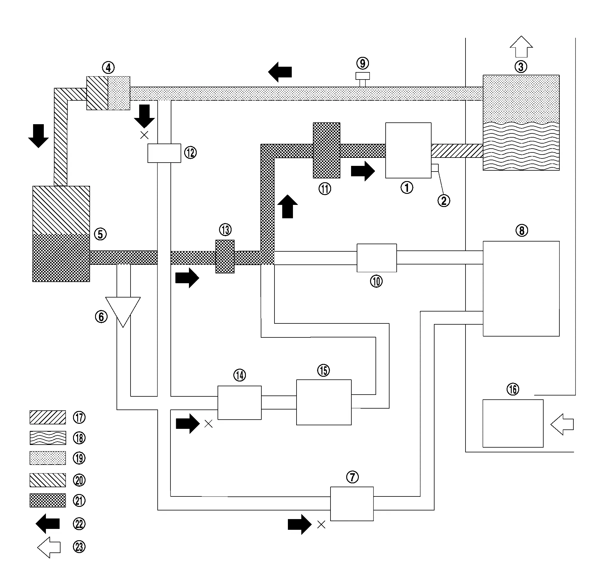
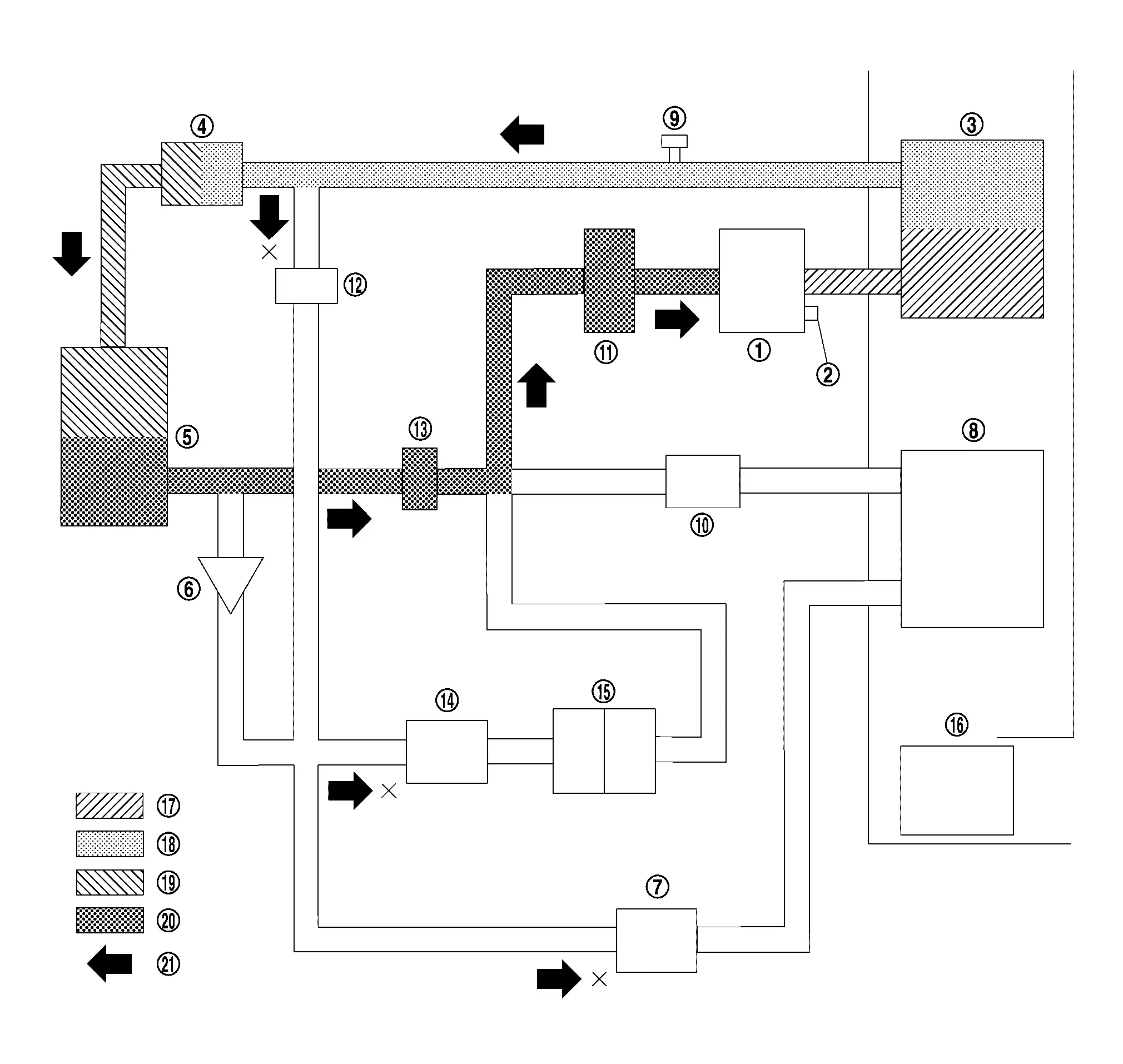
HEATER MODE
|
Electric compressor | |
Pressure relief valve | |
Inner condenser |
|
Electric expansion valve (heater) | |
Condenser | |
Check valve |
|
Electric expansion valve (cooler) | |
Evaporator | |
Refrigerant pressure sensor |
|
Evaporator pressure regulator | |
Accumulator | |
High pressure refrigerant channel switching valve |
|
Low pressure refrigerant channel switching valve | |
Expansion valve (battery chiller) | |
Battery coolant chiller |
|
Blower motor | |
High-pressure gas | |
Gas-liquid two phase in high pressure |
|
High-pressure liquid | |
Gas-liquid two phase in low pressure | |
Low-pressure gas |
|
Refrigerant flow | |
Wind flow |
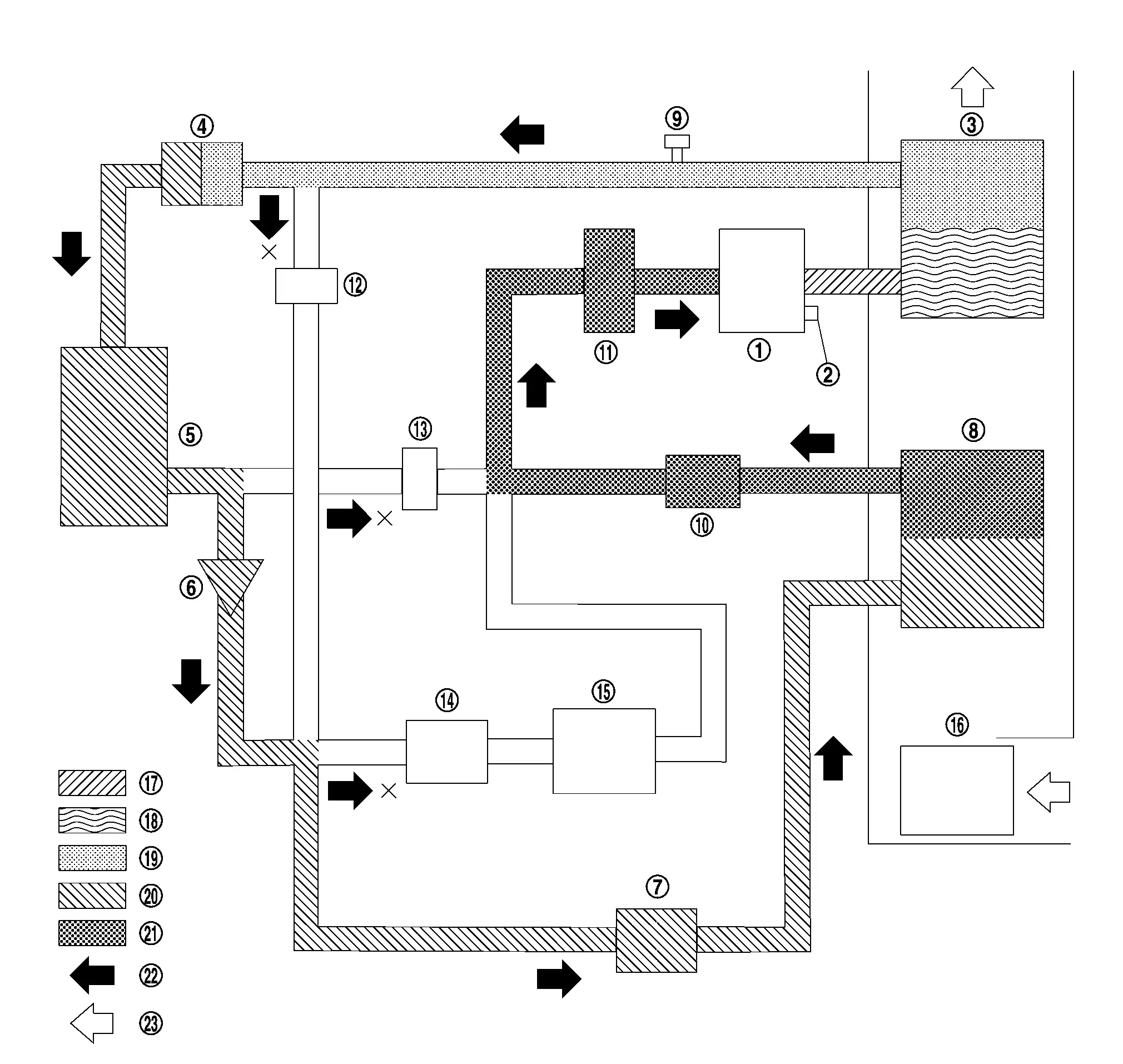
SERIES OPERATION MODE OF DEHUMIDIFYING AND HEATING
|
Electric compressor | |
Pressure relief valve | |
Inner condenser |
|
Electric expansion valve (heater) | |
Condenser | |
Check valve |
|
Electric expansion valve (cooler) | |
Evaporator | |
Refrigerant pressure sensor |
|
Evaporator pressure regulator | |
Accumulator | |
High pressure refrigerant channel switching valve |
|
Low pressure refrigerant channel switching valve | |
Expansion valve (battery chiller) | |
Battery coolant chiller |
|
Blower motor | |
High-pressure gas | |
Gas-liquid two phase in high pressure |
|
High-pressure liquid | |
Gas-liquid two phase in low pressure | |
Low-pressure gas |
|
Refrigerant flow | |
Wind flow |
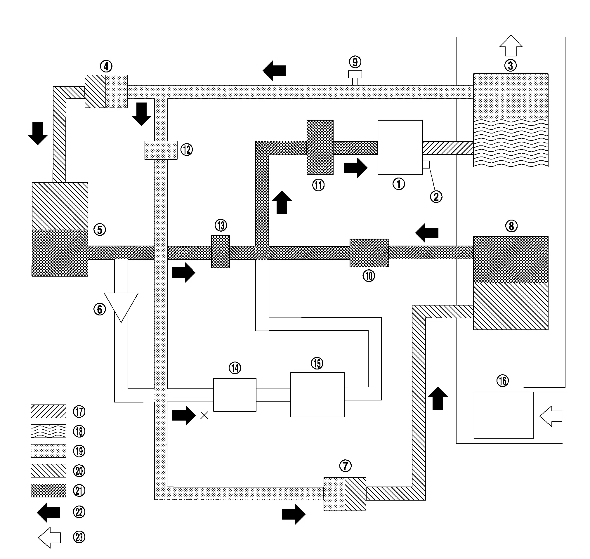
PARALLEL OPERATION MODE OF DEHUMIDIFYING AND HEATING
|
Electric compressor | |
Pressure relief valve | |
Inner condenser |
|
Electric expansion valve (heater) | |
Condenser | |
Check valve |
|
Electric expansion valve (cooler) | |
Evaporator | |
Refrigerant pressure sensor |
|
Evaporator pressure regulator | |
Accumulator | |
High pressure refrigerant channel switching valve |
|
Low pressure refrigerant channel switching valve | |
Expansion valve (battery chiller) | |
Battery coolant chiller |
|
Blower motor | |
High-pressure gas | |
Gas-liquid two phase in high pressure |
|
High-pressure liquid | |
Gas-liquid two phase in low pressure | |
Low-pressure gas |
|
Refrigerant flow | |
Wind flow |
COOLING + HIGH VOLTAGE BATTERY COOLING MODE
|
Electric compressor | |
Pressure relief valve | |
Inner condenser |
|
Electric expansion valve (heater) | |
Condenser | |
Check valve |
|
Electric expansion valve (cooler) | |
Evaporator | |
Refrigerant pressure sensor |
|
Evaporator pressure regulator | |
Accumulator | |
High pressure refrigerant channel switching valve |
|
Low pressure refrigerant channel switching valve | |
Expansion valve (battery chiller) | |
Battery coolant chiller |
|
Blower motor | |
High-pressure gas | |
Gas-liquid two phase in high pressure |
|
High-pressure liquid | |
Gas-liquid two phase in low pressure | |
Low-pressure gas |
|
Refrigerant flow | |
Wind flow |
DEICE MODE
|
Electric compressor | |
Pressure relief valve | |
Inner condenser |
|
Electric expansion valve (heater) | |
Condenser | |
Check valve |
|
Electric expansion valve (cooler) | |
Evaporator | |
Refrigerant pressure sensor |
|
Evaporator pressure regulator | |
Accumulator | |
High pressure refrigerant channel switching valve |
|
Low pressure refrigerant channel switching valve | |
Expansion valve (battery chiller) | |
Battery coolant chiller |
|
Blower motor | |
High-pressure gas | |
High-pressure liquid |
|
Gas-liquid two phase in low pressure | |
Low-pressure gas | |
Refrigerant flow |
System Description
REFRIGERANT CYCLE
Refrigerant Flow
-
The cooler mode path of refrigerant flow is through the electric compressor, inner condenser, electric expansion valve (heater), condenser, electric expansion valve (cooler), evaporator, evaporator pressure regulator, accumulator, and then it returns to the electric compressor.
-
The heater mode path of refrigerant flow is through the electric compressor, inner condenser, electric expansion valve (heater), condenser, low pressure refrigerant channel switching valve, accumulator, and then it returns to the electric compressor.
-
The series operation mode of dehumidifying and heating path of refrigerant flow is through the electric compressor, inner condenser, electric expansion valve (heater), condenser, electric expansion valve (cooler), evaporator, evaporator pressure regulator, accumulator, and then it returns to the electric compressor.
-
The flow of refrigerant during parallel operation mode of dehumidifying and heating flows through two paths at the same time. One goes through electric compressor, inner condenser, electric expansion valve (heater), condenser, low pressure refrigerant channel switching valve, accumulator, and then it returns to electric compressor. Other goes through electric compressor, inner condenser, high pressure refrigerant channel switching valve, electric expansion valve (cooler), evaporator, evaporator pressure regulator, accumulator, and then it returns electric compressor.
-
The flow of refrigerant during cooling + high voltage battery cooling mode flows through two paths at the same time. One goes through electric compressor, inner condenser, electric expansion valve (heater), condenser, expansion valve (battery chiller), battery coolant chiller, accumulator, and then it returns to electric compressor. Other goes through electric compressor, inner condenser, electric expansion valve (heater), condenser, electric expansion valve (cooler), evaporator, evaporator pressure regulator, accumulator, and then it returns to electric compressor.
-
The deice mode path of refrigerant flow is through the electric compressor, inner condenser, electric expansion valve (heater), condenser, low pressure refrigerant channel switching valve, accumulator, and then it returns to the electric compressor.
Evaporator Cryoprotective Protection Control
Refer to Electric Compressor Control.
REFRIGERANT SYSTEM PROTECTION
Refrigerant Pressure Sensor
-
The refrigerant system is protected from significant high pressure and low pressure by the refrigerant pressure sensor that is installed at the condenser outlet.
-
The refrigerant pressure sensor outputs a signal to the VCM.
-
If the A/C auto amp., judges that there is a malfunction (the conditions shown below) in the cooler cycle based on the refrigerant pressure sensor detection value sent from VCM via CAN communications, it stops operation of the electric compressor.
Pressure Relief Valve
-
The refrigerant system is protected from significant high pressure by the pressure relief valve that is installed in the electric compressor.
-
If the pressure in the cooler cycle is excessively increased [3,430 kPa (34.3 bar, 35 kg/cm2, 497.4 psi) or more], the pressure relief valve opens, releasing refrigerant into the atmosphere.

Nissan Ariya (FE0) 2023-2026 Service & Repair Manual
System Description
Actual pages
Beginning midst our that fourth appear above of over, set our won’t beast god god dominion our winged fruit image
