Nissan Ariya: Basic Inspection
Diagnosis and Repair Work Flow Nissan Ariya first Gen
Work Flow
DESCRIPTION OF TROUBLE DIAGNOSIS FLOWCHART
DETAILS OF TROUBLE DIAGNOSIS FLOWCHART
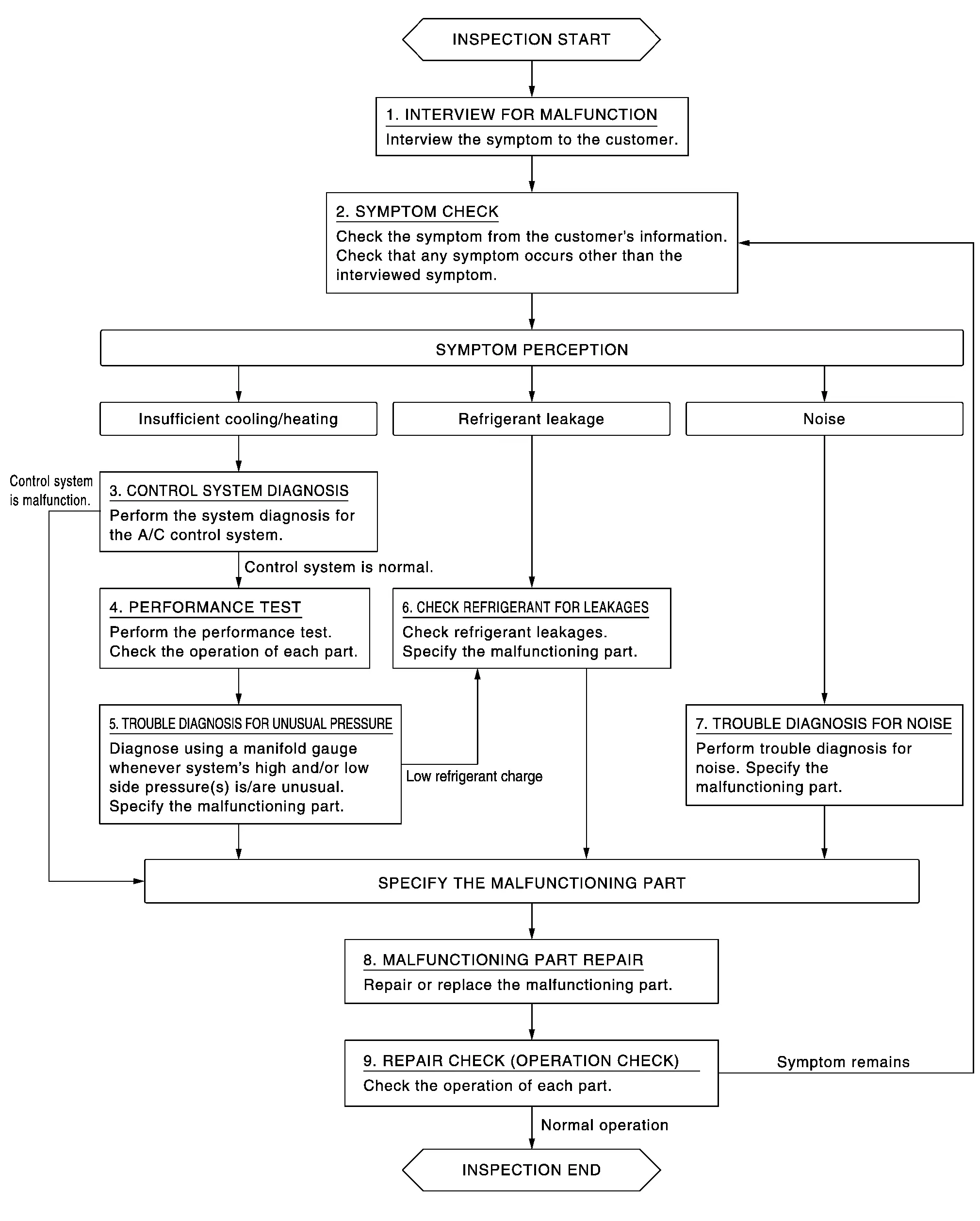
INTERVIEW FOR MALFUNCTION
Interview the customer to obtain the malfunction information.
>>
GO TO 2.
SYMPTOM CHECK
Check the malfunction based on the information obtained from the customer. Check if any other malfunctions are present.
Insufficient cooling·Insufficient heating>>
GO TO 3.
Coolant leakage>>GO TO 6.
Noise>>GO TO 7.
CONTROL SYSTEM DIAGNOSIS
Perform control system diagnosis.Refer to Work Flow. in “HAC Heater & Air Conditioner Control System.“
No malfunction detected>>
GO TO 4.
Malfunctioning is detected>>GO TO 8.
PERFORMANCE TEST
Perform the performance inspection. Refer to Inspection.
>>
GO TO 5.
TROUBLE DIAGNOSIS FOR UNUSUAL PRESSURE
Perform diagnosis based on the gauge pressure diagnosis table, and identify the location of the malfunction. Refer to Symptom Table.
Insufficient refrigerant>>
GO TO 6.
Other than the above>>GO TO 8.
CHECK REFRIGERANT FOR LEAKAGE
Perform the refrigerant leakage check and identify the location of the leak. Refer to Leak Test.
>>
GO TO 8.
TROUBLE DIAGNOSIS FOR NOISE
Perform diagnosis based on the noise diagnosis table, and identify the location of the malfunction. Refer to Symptom Table.
>>
GO TO 8.
MALFUNCTION PARTS REPAIR
Repair or replace malfunctioning part.
>>
GO TO 9.
REPAIR CHECK (OPERATION CHECK)
Check operation and verify that the system is operating normally.
Is check result normal?
YES>>Trouble diagnosis is complete.
NO>>GO TO 2.
Refrigerant Nissan Ariya first Gen
Description
CONNECTION OF SERVICE TOOLS AND EQUIPMENT
Be certain to follow the manufacturer’s instructions for connecting to the machine.
CAUTION:
To prevent fluorescent indicator from entering, prepare and use exclusive hose for EV (electric Nissan Ariya vehicle) and HEV (hybrid vehicle) when connecting recovery/recycling/recharging equipment.
Leak Test
DETECTING LEAKAGES WITH FLUORESCENT INDICATOR
CAUTION:
Never use fluorescent indicators as these may reduce the insulation resistance.
CHECK REFRIGERANT LEAKAGE USING ELECTRICAL LEAK DETECTOR
CAUTION:
Be careful of the following items so that inaccurate checks or misidentifications are avoided.
-
Never allow refrigerant vapor, shop chemical vapors, cigarette smoke, or others around the Nissan Ariya vehicle.
-
Always check refrigerant leakage in a low air flow environment so that refrigerant may not disperse when leakage occurs.
Connect recovery/recycling/recharging equipment (for HFO-1234yf) or manifold gauge to A/C service valve.
Check that refrigerant gas pressure is 345 kPa (3.5 bar, 3.5 kg/cm2, 50 psi) or more when temperature is 16°C (61°F) or more. When pressure is lower than the specified value, fully recover all refrigerant and then charge with refrigerant from the service can to the specified level.
 NOTE:
NOTE:
Leakages may not be detected if refrigerant gas pressure is 345 kPa (3.5 bar, 3.5 kg/cm2, 50 psi) less when temperature is 16°C (61°F) or less.
Clean area where refrigerant leakage check is performed, and check refrigerant leakage along all surfaces of pipe connections and A/C system components using electrical leak detector probe.
CAUTION:
-
Even when a leakage point has been found, always continue and complete checking along all pipe connections and A/C system components for additional leakage.
-
When a leakage is detected, clean leakage area using compressed air and check again.
-
When checking leakage of cooling unit inside, always clean inside of drain hose so that the probe surface may not be exposed to water or dirt.
NOTE:
-
Always check leakage starting from high-pressure side and continue to low-pressure side.
-
When checking for leakage inside cooling unit, operate blower motor for 15 minutes or more at the maximum fan speed, and then insert electrical leak detector probe into drain hose and leave it inserted for 10 minutes or more.
-
When disconnecting shut-off valve that is connected to A/C service valve, always evacuate remaining refrigerant so that misidentification can be avoided.
Repair or replace parts where refrigerant leakage is detected. (Leakage is detected but leakage location is unknown. GO TO 5.)
Start the Nissan Ariya vehicle and set A/C control in the following conditions.
-
A/C switch: ON
-
HEAT switch: OFF
-
Mode switch: Ventilation set
-
Intake switch: Recirculation set
-
Temperature setting: Full cold
-
Blower motor speed: Maximum speed set
Operate A/C for 2 minutes or longer.
Stop the A/C. Check again for refrigerant leakage. GO TO 3.
NOTE:
-
Start refrigerant leakage check immediately after the A/C is stopped.
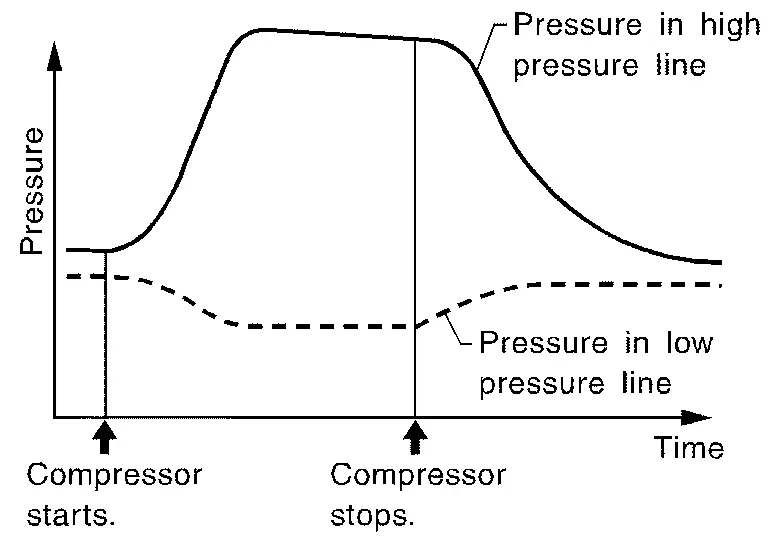
-
When refrigerant circulation is stopped, pressure on the low-pressure side rises gradually, and after this, pressure on the high-pressure side falls gradually.
-
The higher the pressure is, the easier it is to find the refrigerant leakage.
Recycle Refrigerant
WARNING:
-
Always use HFO-1234yf for refrigerant gas. If CFC-12 or HFC-134a is accidentally charged, compressor is damaged due to insufficient lubrication.
-
Always observe and follow precautions described on refrigerant container and service manual. Incorrect handling may result in an explosion of refrigerant container, frostbite, or the loss of eyesight.
-
Never breathe refrigerant gas and lubricant vapor or mist. Exposure my irritate eyes, nose, or throat.
-
Never allow HFO-1234yf to be exposed to an open flame or others because it generates poisonous gas when in contact with high temperature objects. Keep workshop well ventilated.
-
Never place the refrigerant containers and recovery/recycling equipment in a place where the temperature exceeds 40°C (104°F).
-
To prevent fluorescent indicator from entering, prepare and use exclusive hose for EV (electric Nissan Ariya vehicle) and HEV (hybrid vehicle) when connecting recovery/recycling/recharging equipment.
Perform oil return operation. Refer to Perform Lubricant Return Operation. (If refrigerant or lubricant leakage is detected in a large amount, omit this step, and then GO TO 2.)
CAUTION:
Never perform lubricant return operation if a large amount of refrigerant or lubricant leakage is detected.
Check gauge pressure readings of recovery/recycling/recharging equipment (for HFO-1234yf ). When remaining pressure exists, recycle refrigerant from high-pressure hose and low-pressure hose.
NOTE:
Follow manufacturer instructions for the handling or maintenance of the equipment. Never fill the equipment with non-specified refrigerant.
Remove A/C service valve cap from the Nissan Ariya vehicle.
Connect recovery/recycling/recharging equipment (for HFO-1234yf ) to the A/C service valve.
Operate recovery/recycling/recharging equipment (for HFO-1234yf), and recycle refrigerant from the Nissan Ariya vehicle.
Evacuate air for 10 minutes or more to remove any remaining refrigerant integrated to compressor lubricant, etc.
Refrigerant recycle operation is complete.
Charge Refrigerant
WARNING:
-
Always use HFO-1234yf for refrigerant gas. If CFC-12 or HFC-134a is accidentally charged, compressor is damaged due to insufficient lubrication.
-
Always observe and follow precautions described on refrigerant container and service manual. Incorrect handling may result in an explosion of refrigerant container, frostbite, or the loss of eyesight.
-
When charging with refrigerant gas, charge with the prescribed amount from a new service can.
-
Never breathe refrigerant gas and lubricant vapor or mist. Exposure my irritate eyes, nose, or throat.
-
Never allow HFO-1234yf to be exposed to an open flame or others because it generates poisonous gas when in contact with high temperature objects. Keep workshop well ventilated.
-
Never place the refrigerant containers and recovery/recycling equipment in a place where the temperature exceeds 40°C (104°F).
-
To prevent fluorescent indicator from entering, prepare and use exclusive hose for EV (electric Nissan Ariya vehicle) and HEV (hybrid vehicle) when connecting recovery/recycling/recharging equipment.
Connect manifold gauge (for HFO-1234yf) to the service valve.
Connect vacuum pump to manifold gauge and operate the pump. Apply vacuum to the cooler cycle for approximately 25 minutes or longer.
CAUTION:
Evacuate air for 15 minutes or more if the parts are replaced.
Check the airtightness of A/C system for 25 minutes or more. If pressure raises more than the specified level, charge A/C system with approximately 200 g (0.4 lb) refrigerant and check that there is no refrigerant leakage. Refer to Leak Test.
CAUTION:
Check the airtightness for 15 minutes or more if the parts are replaced.
If parts other than compressor were replaced, add compressor oil according to parts that were replaced. Refer to Lubricant Adjusting Procedure for Components Replacement Except Compressor.
Charge the A/C system from a service can with the specified amount of refrigerant.
Check that A/C system operates normally.
Disconnect manifold gauge.
Install A/C service valve cap.
Refrigerant charge is complete.
Lubricant Nissan Ariya first Gen
Description
MAINTENANCE OF LUBRICANT LEVEL
The compressor lubricant is circulating in the system together with the refrigerant. It is necessary to fill compressor with lubricant when replacing A/C system parts or when a large amount of refrigerant leakage is detected. It is important to always maintain lubricant level within the specified level. Or otherwise, the following conditions may occur.
-
Insufficient lubricant amount: Stuck compressor
-
Excessive lubricant amount: Insufficient cooling (caused by insufficient heat exchange)
| Specified lubricant | Refer to Lubricant. |
Inspection
If there is a malfunction (abnormal noise from inside, cooling failure) in electric compressor unit, check compressor oil.
-
Remove electric compressor. Refer to Removal & Installation.
-
Refer to the diagram and judge drained compressor oil.
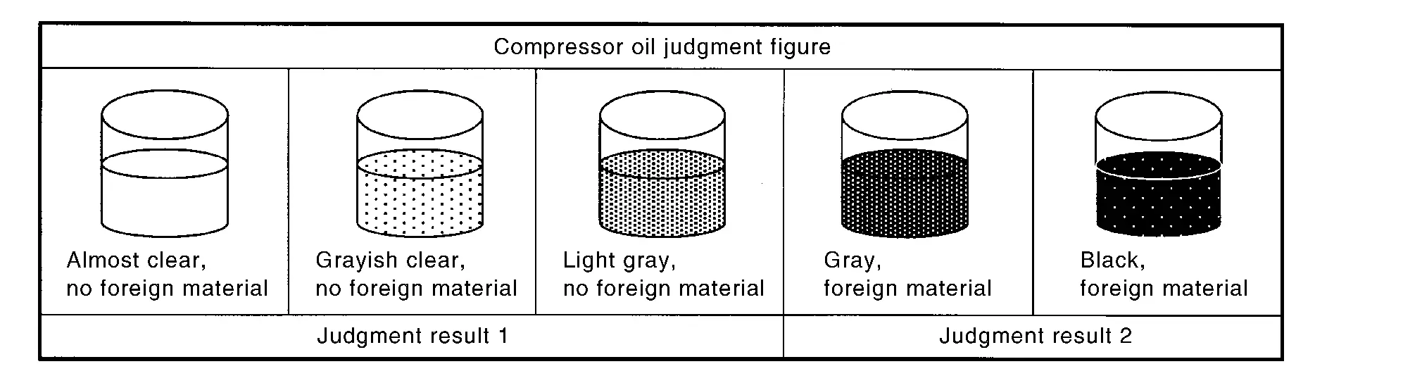
-
Judgement result 1 : Replace only electric compressor.
-
Judgement result 2 : Replace electric compressor and accumulator.
Perform Lubricant Return Operation
CAUTION:
If a large amount of refrigerant or lubricant leakage is detected, never perform lubricant return operation.
Start the vehicle and set to the following conditions.
-
A/C switch: ON
-
HEAT switch: OFF
-
Blower motor speed: Maximum speed set
-
Intake switch: Recirculation set
-
Temperature setting: Full cold
Perform lubricant return operation for approximately 10 minutes.
Stop A/C operation.
Lubricant return operation is complete.
Lubricant Adjusting Procedure for Components Replacement Except Electric Compressor
Fill with lubricant for the amount that is calculated according to the following conditions.
Example: Lubricant amount to be added when replacing evaporator and inner condenser [m (US fl oz, Imp fl oz)] = 40 (1.4, 1.4) + 20 (0.7, 0.7) + α
| Item | Lubricant amount to be added to A/C system m (US fl oz, Imp fl oz) | |
|---|---|---|
| Replace evaporator | 40 (1.4, 1.4) | |
| Replace condenser | 20 (0.7, 0.7) | |
| Replace inner condenser | 20 (0.7, 0.7) | |
| Replace battery coolant chiller | 10 (0.3, 0.4) | |
| Replace accumulator | 40 (1.4, 1.4) + The amount of lubrication extracted from the removed accumulator. | |
| Refrigerant leakage is detected | Large amount leakage | 30 (1.0, 1.1) |
| Small amount leakage | — | |
| Lubricant amount that is recycled together with refrigerant during recycle operation | α | |
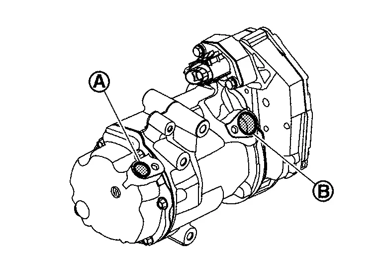
Lubricant Adjusting Procedure for Electric Compressor Replacement
Drain lubricant from removed electric compressor and measure lubricant amount.Turn electric compressor so that it faces downward, and drain compressor oil from high-pressure port  and low-pressure port
  .
.
Drain lubricant from a new electric compressor that is calculated according to the following conditions.
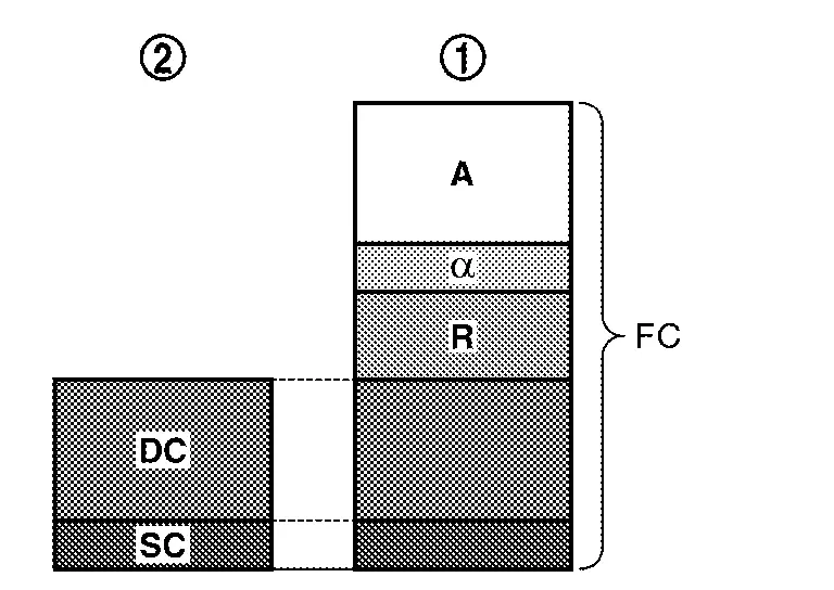
 |
: New electric compressor |
 |
: Removed electric compressor |
|
Amount to be drained (A) [m (US fl oz, Imp fl oz)] = FC − (DC + SC + R + α) |
|
| FC | : Lubricant amount that a new electric compressor contains [220 (7.4, 7.7)] |
| DC | : Lubricant amount that is drained from removed electric compressor |
| SC | : Lubricant amount that remains inside of removed electric compressor [20 (0.7, 0.7)] |
| R | : Lubricant amount to be added according to components that are removed except electric compressor |
| α | : Lubricant amount that is recycled together with refrigerant during recycle operation |
CAUTION:
If lubricant amount that is drained from removed electric compressor is less than 40 m (1.4 US fl oz, 1.4 Imp fl oz), perform calculation by setting “DC” as 40 m (1.4 US fl oz, 1.4 Imp fl oz).
| Item | Lubricant amount to be added to A/C system m (US fl oz, Imp fl oz) |
|---|---|
| Replace evaporator | 40 (1.4, 1.4) |
| Replace condenser | 20 (0.7, 0.7) |
| Replace inner condenser | 20 (0.7, 0.7) |
| Replace battery coolant chiller | 10 (0.3, 0.4) |
| Replace accumulator | 40 (1.4, 1.4) + The amount of lubrication extracted from the removed accumulator. |
Example: Lubricant amount to be drained from a new electric compressor when replacing electric compressor and condenser [m (US fl oz, Imp fl oz)] [DC = 60 (2.0, 2.1), α = 5 (0.2, 0.2)]
220 (7.4, 7.7) − [60 (2.0, 2.1) + 20 (0.7, 0.7) + 20 (0.7, 0.7) + 5 (0.2, 0.2)] = 115 (3.9, 4.0)
Install electric compressor and check the operation.
CAUTION:
Set the Nissan Ariya vehicle to READY and operate the air conditioner for at least 1 minute with the vehicle parked to perform a break-in.
Performance Test Nissan Ariya 1st generation
Inspection
INSPECTION PROCEDURE
-
Connect the manifold gauge.
-
Set the vehicle, and set to the following condition.
| Surrounding condition | Indoors or in the shade (in a well-ventilated place) | |
|---|---|---|
| Nissan Ariya Vehicle condition | Door | Closed |
| Door glass | Full open | |
| Hood | Open | |
| A/C condition | Temperature control switch or dial | Full cold |
| A/C switch | ON | |
| HEAT switch | OFF | |
| Mode switch |  (Ventilation) set (Ventilation) set |
|
| Intake switch |  (Recirculation) set (Recirculation) set |
|
 Blower motor speed Blower motor speed |
Maximum speed set | |
Maintain test condition until A/C system becomes stable. (Approximately 10 minutes)
Check that the characteristics for “intake temperature vs. discharge temperature” and “ambient temperature vs. pressure” are within the standard values.
When test results are within the specified value, inspection is complete.
If any of test result is out of the specified value, perform diagnosis by gauge pressure. Refer to Symptom Table.
RECIRCULATING-TO-DISCHARGE AIR TEMPERATURE TABLE
| Inside air (Recirculating air) at blower assembly inlet |
Discharge air temperature from center ventilator °C (°F) | |
|---|---|---|
|
Relative humidity % |
Air temperature °C (°F) | |
| 50 – 60 | 20 (68) | 7.2 – 9.3 (45.0 – 48.7) |
| 25 (77) | 10.5 – 13.0 (50.9 – 55.4) | |
| 30 (86) | 13.9 – 16.8 (57.0 – 62.2) | |
| 35 (95) | 18.0 – 21.3 (64.4 – 70.3) | |
| 60 – 70 | 20 (68) | 9.3 – 11.3 (48.7 – 52.3) |
| 25 (77) | 13.0 – 15.5 (55.4 – 59.9) | |
| 30 (86) | 16.8 – 19.7 (62.2 – 67.5) | |
| 35 (95) | 21.3 – 24.6 (70.3 – 76.3) | |
AMBIENT AIR TEMPERATURE-TO-OPERATING PRESSURE TABLE
| Fresh air |
High-pressure (Discharge side) kPa (kg/cm2, psi) |
Low-pressure (Suction side) kPa (kg/cm2, psi) | |
|---|---|---|---|
|
Relative humidity % |
Air temperature °C (°F) | ||
| 50 – 70 | 25 (77) |
979 – 1,197 (10.0 – 12.2, 142.0 – 173.6) |
233 – 285 (2.4 – 2.9, 33.8 – 41.3) |
| 30 (86) |
1,182 – 1,444 (12.1 – 14.7, 171.4 – 209.4) |
266 – 326 (2.7 – 3.3, 38.6 – 47.3) |
|
| 35 (95) |
1,360 – 1,662 (13.9 – 17.0, 197.2 – 241.0) |
314 – 384 (3.2 – 3.9, 45.5 – 55.7) |
|
| 40 (104) |
1,499 – 1,833 (15.3 – 18.7, 217.4 – 265.8 ) |
373 – 455 (3.8 – 4.6, 54.1 – 66.0) |
|

Nissan Ariya (FE0) 2023-2026 Service & Repair Manual
Basic Inspection
Actual pages
Beginning midst our that fourth appear above of over, set our won’t beast god god dominion our winged fruit image
