Nissan Ariya: Removal and Installation
Instrument Panel Assembly Nissan Ariya first Gen
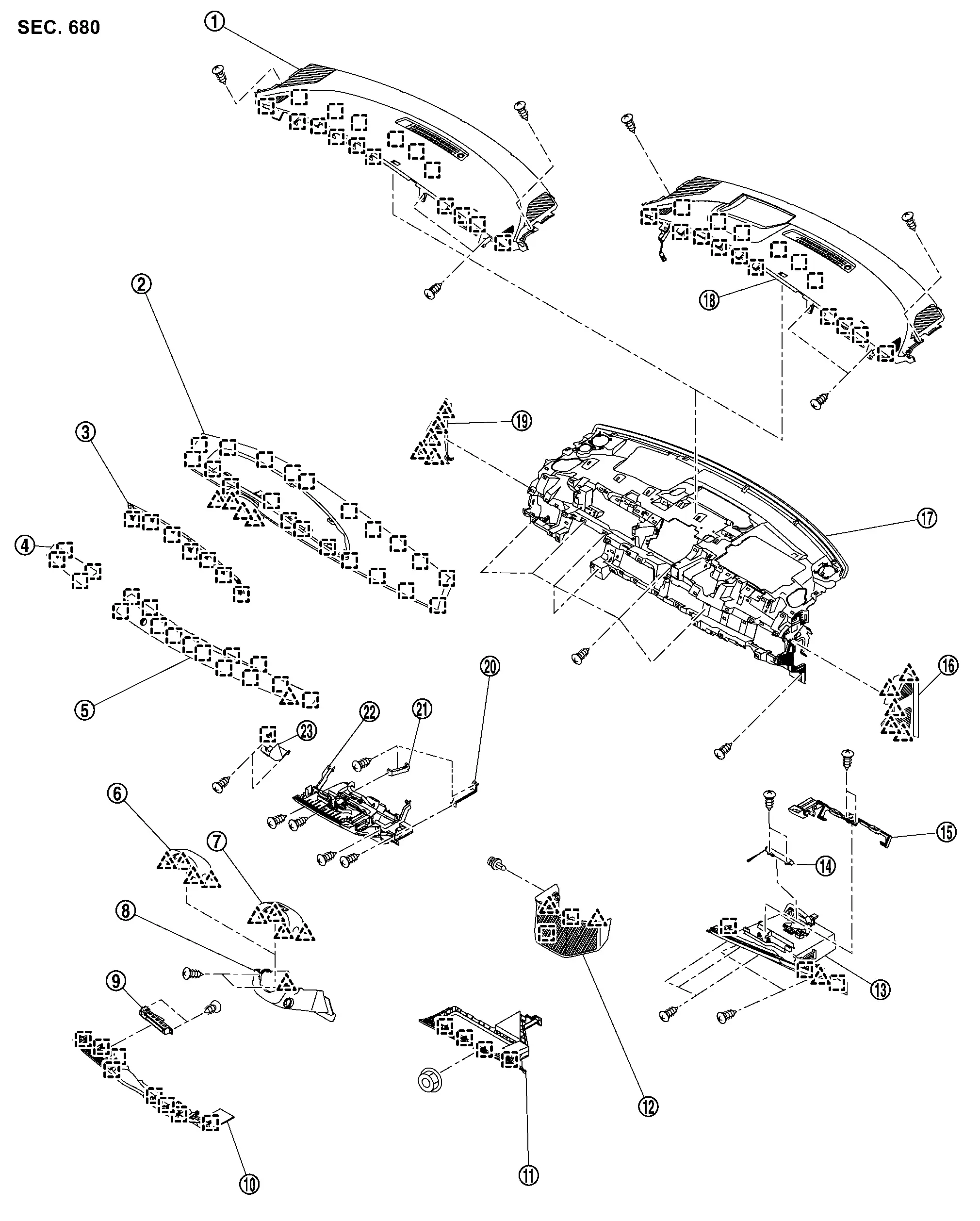
Exploded View
 |
Instrument upper garnish (without head up display) |  |
Instrument pad B |  |
Meter cover |
 |
Instrument finisher A |  |
Instrument finisher B |  |
Steering column cover upper (without driver monitor camera) |
 |
Steering column cover upper (with driver monitor camera) |  |
Steering column cover lower |  |
Switch bracket |
 |
Instrument lower panel |  |
Instrument lower cover |  |
Instrument lower cover center |
 |
Glove box assembly |  |
Glove box damper |  |
Glove box lock |
 |
Instrument mask LH |  |
Instrument panel assembly |  |
Instrument upper garnish (with head up display) |
 |
Instrument mask RH |  |
Bracket RH |  |
Bracket LH |
 |
Center box / Flexible center storage |  |
Electrical parking brake switch | ||
 |
: Pawl | ||||
 |
: Metal clip | ||||
Removal & Installation
WORK STEP
When removing instrument panel assembly, integrated interface display and AV control unit take steps in the order shown by the numbers below.
| PARTS | INSTRUMENT PANEL ASSEMBLY | AV CNTROL UNIT | INTEGRATED INTERFACE DISPLAY |
|---|---|---|---|
| Front kicking plate LH / RH | [1] | ||
| Body side welt | [2] | ||
| Dash side finisher LH / RH | [3] | ||
| Instrument mask RH (RHD models is LH) | [4] | ||
| Instrument lower cover | [5] | ||
| Glove box assembly | [6] | ||
| Passenger knee air bag module | [7] | ||
| Instrument mask LH | [8] | ||
| Instrument lower panel | [9] | ||
| Driver knee air bag module | [10] | ||
| Instrument lower cover center | [11] | ||
| Instrument finisher B | [12] | ||
| Instrument finisher A | [13] | ||
| Electrical parking brake switch bracket | [14] | ||
| Center box / Flexible center storage | [15] | ||
| Steering wheel | [16] | ||
| Meter cover | [17] | [1] | [1] |
| Integrated interface display | [18] | [2] | [2] |
| Instrument pad B | [19] | [3] | |
| Sunload sensor | [20] | [4] | |
| Front pillar garnish LH / RH | [21] | [5] | |
| Passenger air bag module harness connector | [22] | [6] | |
| Passenger air bag module mounting bolt | [23] | [7] | |
| Instrument upper garnish | [24] | [8] | |
| Center ventilator grill | [25] | ||
| Side ventilator grill | [26] | ||
| AV control unit | [27] | [9] | |
| Intelligent key unit | [28] | ||
| Meter speaker | [29] | ||
| Front squawker | [30] | ||
| Steering column cover | [31] | ||
| Spiral cable | [32] | ||
| Combination switch | [33] | ||
| Instrument panel assembly | [34] |
[]: Number indicates step in removal procedure.
REMOVAL
WARNING:
When servicing, disconnect 12V battery negative terminal. Refer to PRECAUTIONS FOR REMOVING BATTERY TERMINAL : Precautions.
CAUTION:
-
When removing, always use a remover tool that is made of plastic.
-
Always apply the parking brake before performing removal and installation.
Remove front kicking plate LH/RH. Refer to Removal & Installation.
Remove body side welt of instrument panel section. Refer to Removal & Installation.
Remove dash side finisher. Refer to Removal & Installation.
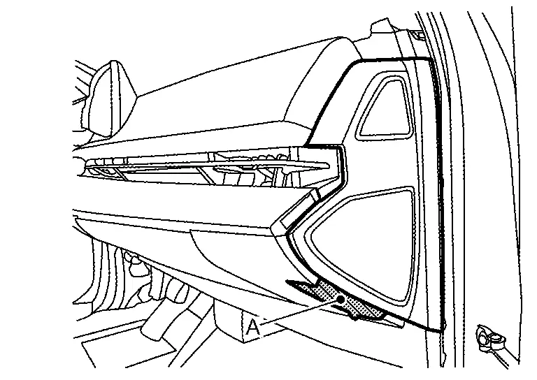
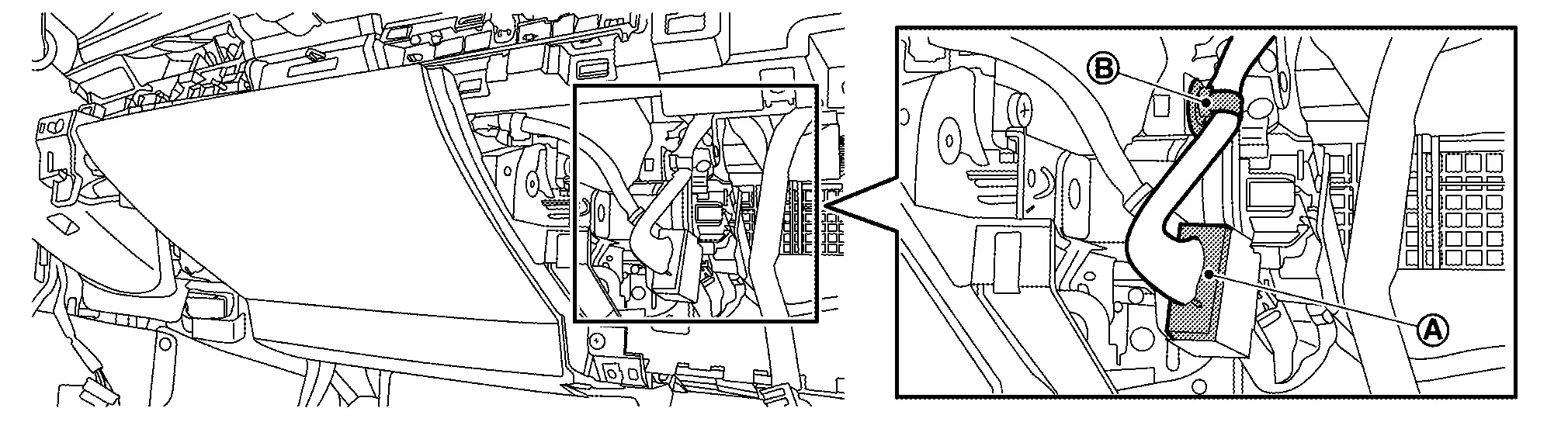
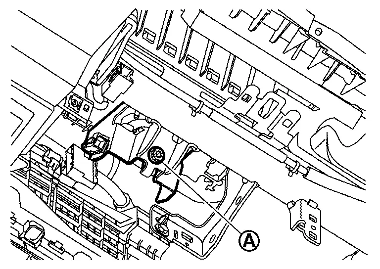
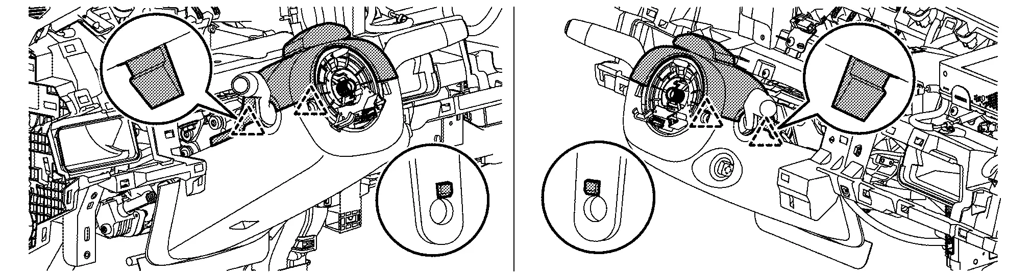
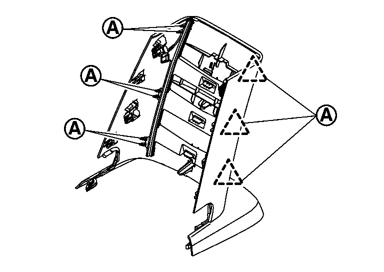
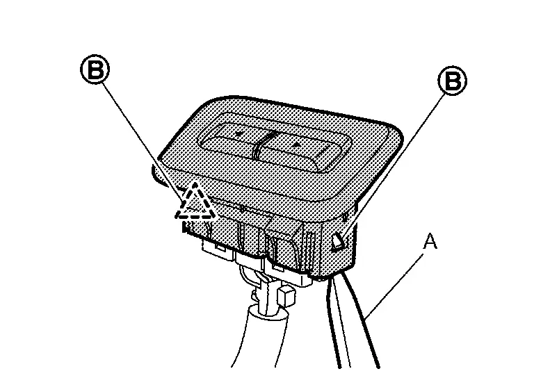
Remove instrument mask RH.Apply protective tape (A) on the part to protect it from damage.
|
: Pawl |
| B | : 90 mm (3.54 in) |
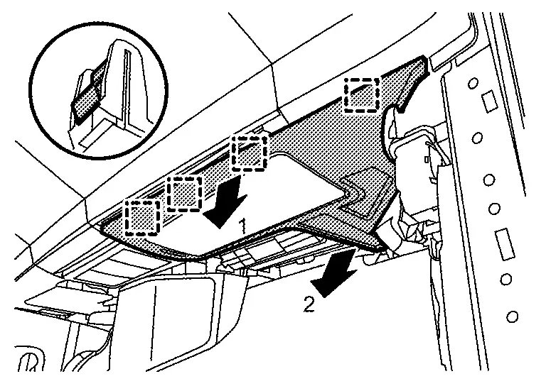
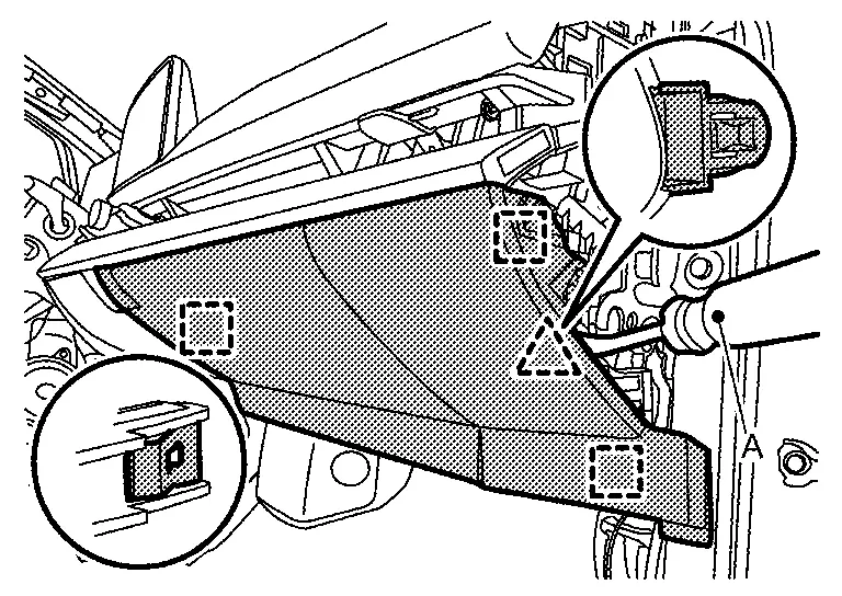
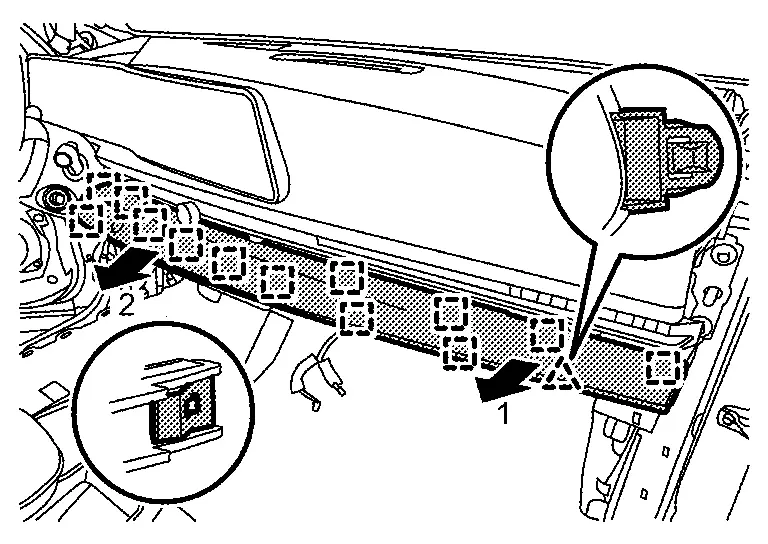
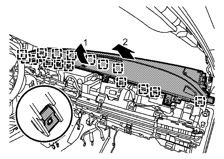
Remove instrument lower cover.Remove instrument lower cover fixing trim nut. Disengage fixing metal clips according to numerical order 1→2 indicated by arrows as shown in the figure, and then remove instrument lower cover.
|
: Metal clip |
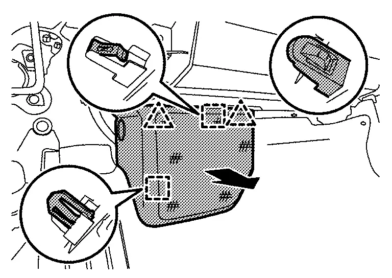
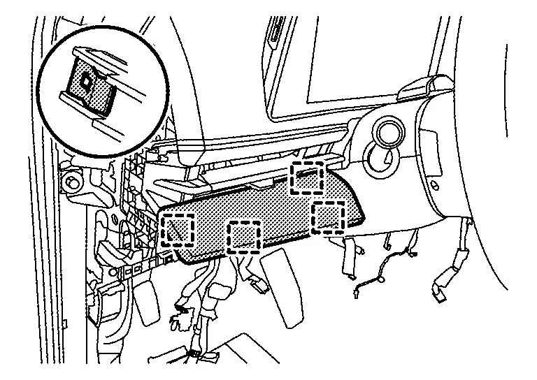
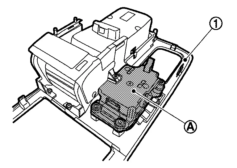
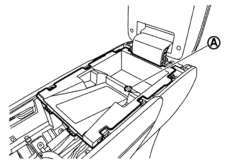
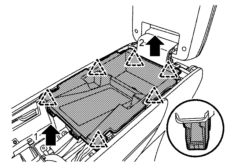
Remove glove box assembly.Remove glove box assembly fixing screws  .
.
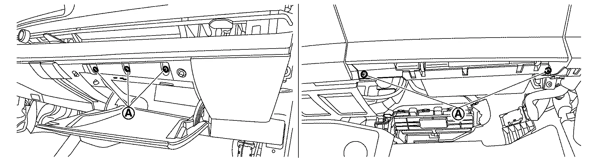
|
: Pawl |
|
: Metal clip |
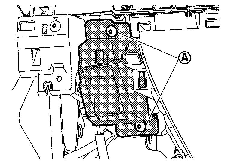
Remove passenger knee air bag module. Refer to Removal & Installation.
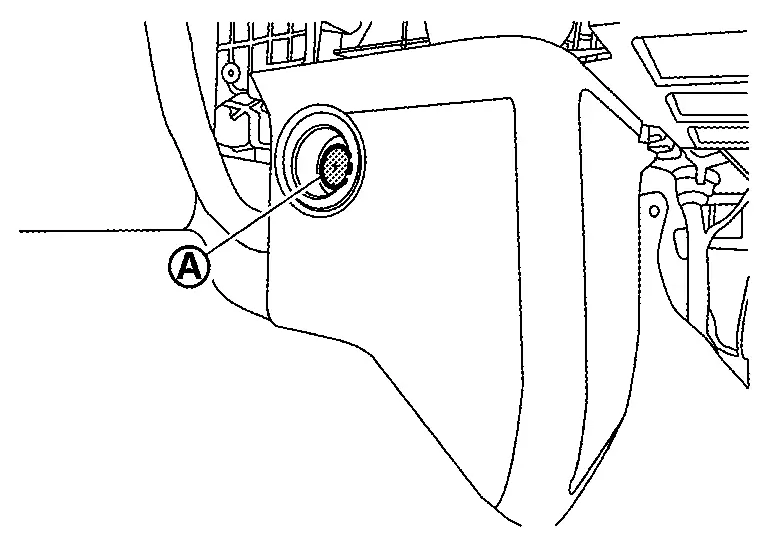
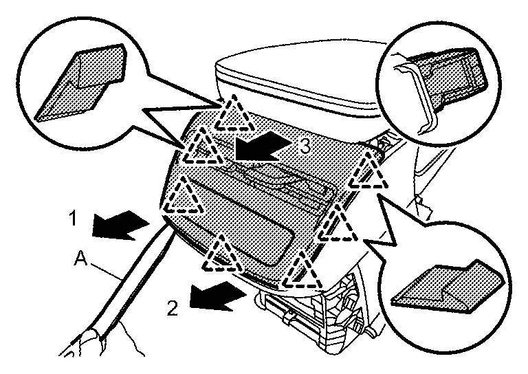
Remove instrument mask LH.Apply protective tape (A) on the part to protect it from damage.
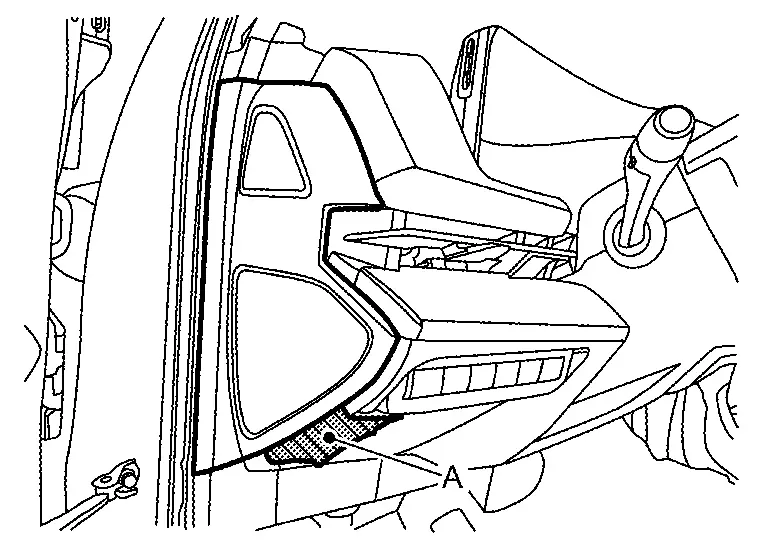
|
: Pawl |
| B | : 90 mm (3.54 in) |
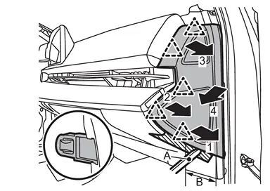
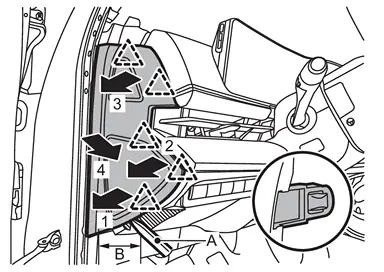
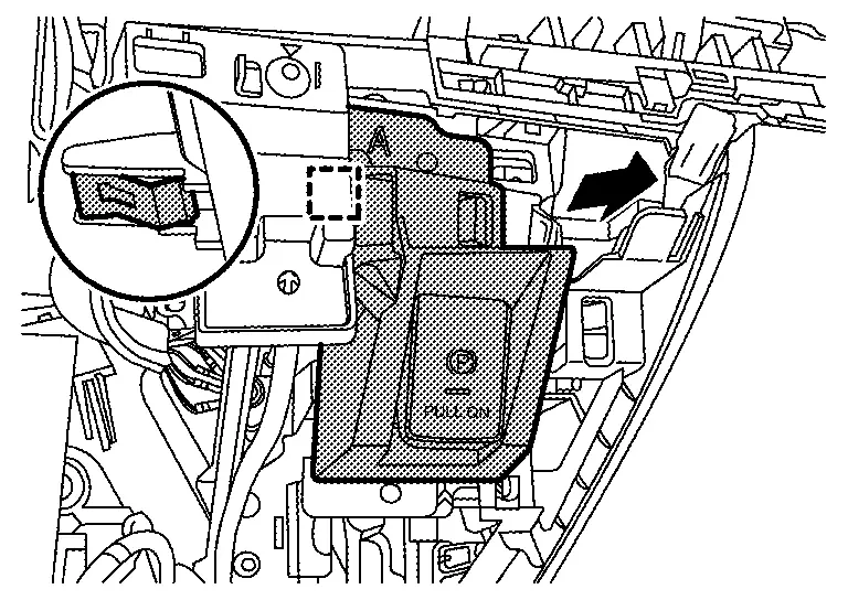
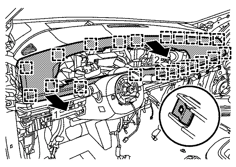
Remove instrument lower panel.Disengage fixing metal clips according to numerical order 1→4 indicated by arrows as shown in figure.
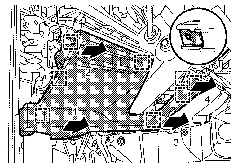
|
: Metal clip |
Remove driver knee air bag module. Refer to Removal and Installation.
Remove instrument lower cover center.Remove fixing clip .
|
: Pawl |
|
: Metal clip |
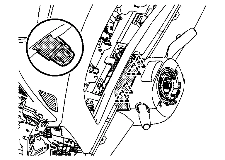
Remove instrument finisher B.Disengage fixing pawl and metal clips according to numerical order 1→2 indicated by arrows as shown in figure.
|
: Pawl |
|
: Metal clip |
Disengage fixing metal clips, and them remove instrument finisher A.
|
: Metal clip |
Remove electric parking brake switch.Remove electric parking brake switch fixing screws .
|
: Metal clip |
Remove center box / flexible center storage.Disconnect harness connector , and then disengage body harness fixing clip  (flexible center storage).
.
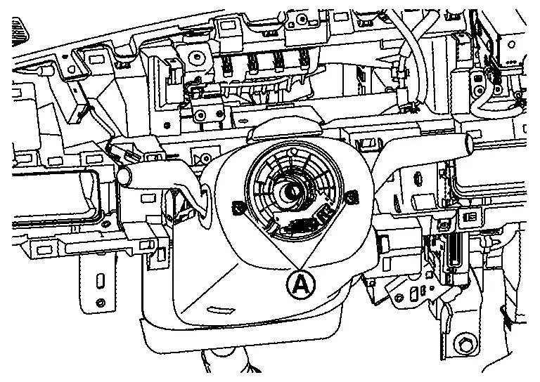
Remove steering wheel. Refer to STEERING WHEEL : Removal & Installation.
Disengage fixing metal clips according to numerical order 1→3 indicated by arrows as shown in figure using a remover tool (A), and then remove meter cover.
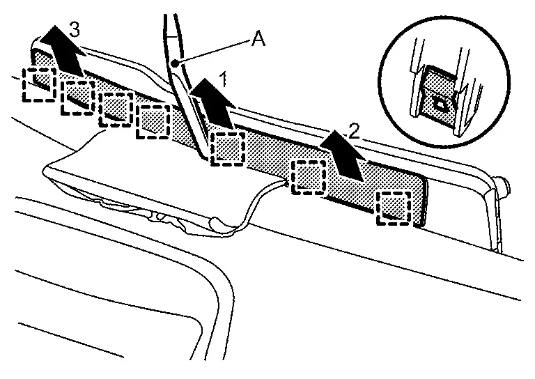
CAUTION:
Use the shop-cloth on instrument pad B to prevent damage.
|
: Metal clip | ||||
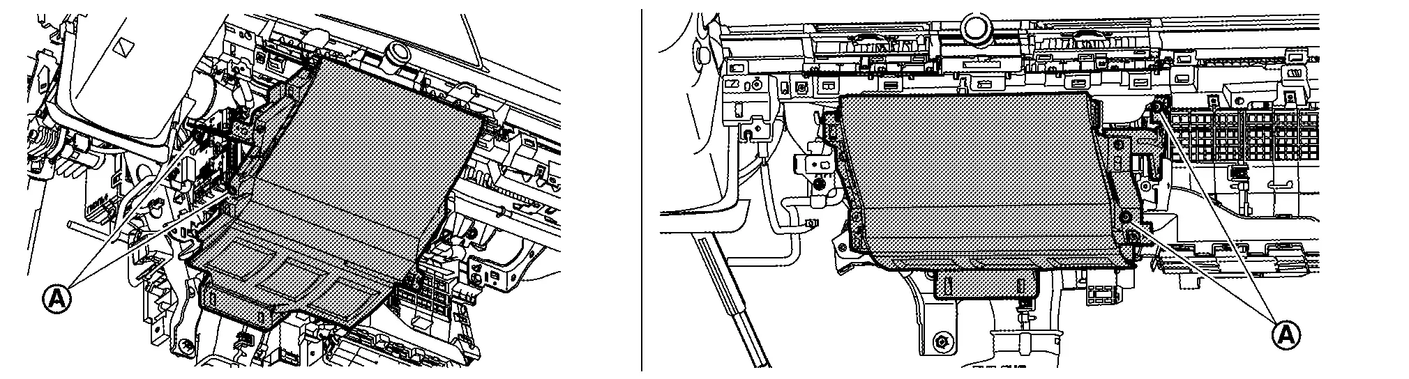
Remove integrated interface display. Refer to Removal and Installation.
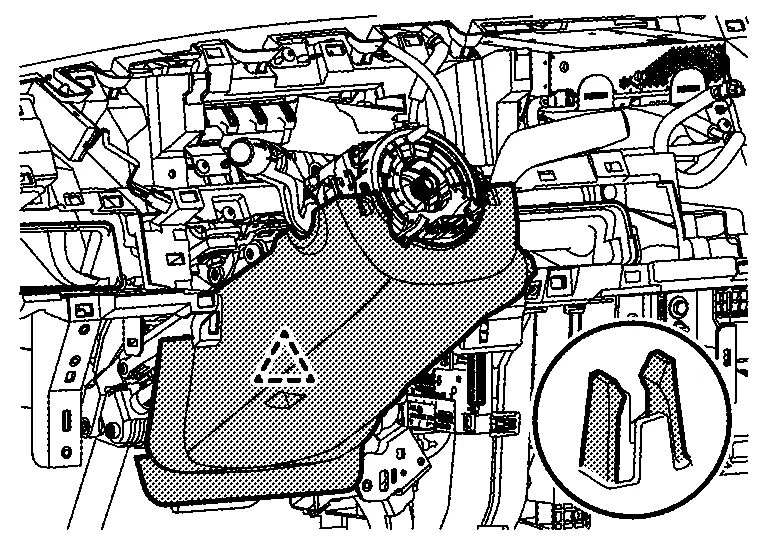
Remove instrument pad B.Pull up the skirt part of instrument pad B to disengage fixing pawls, and then remove it from steering column cover upper.
|
: Pawl |
|
: Metal clip | ||||
Remove sunload sensor. Refer to Removal & Installation.
Remove front pillar garnish. Refer to Removal & Installation.
Remove passenger air bag module harness connector.
Remove passenger air bag module mounting bolt .
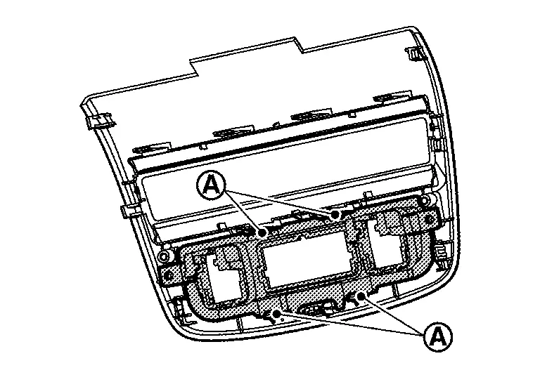
Remove instrument upper garnish.Remove fixing screws .
-
Upper side
-
Passenger seat side
|
: Metal clip |
Remove center ventilator grill. Refer to Removal & Installation.
Remove side ventilator grill. Refer to Removal & Installation.
Remove AV control unit. Refer to Removal & Installation.
Remove intelligent key unit. Refer to Removal and Installation.
Remove meter speaker. Refer to Removal and Installation.
Remove front squawker. Refer to Removal & Installation.
Remove steering column cover.Remove steering column cover fixing screws .
|
: Pawl |
|
: Pawl |
Remove spiral cable. Refer to Removal & Installation.
Remove combination switch. Refer to Removal and Installation.
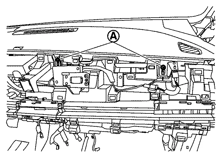
Remove instrument panel assembly.Remove instrument panel assembly fixing screws .
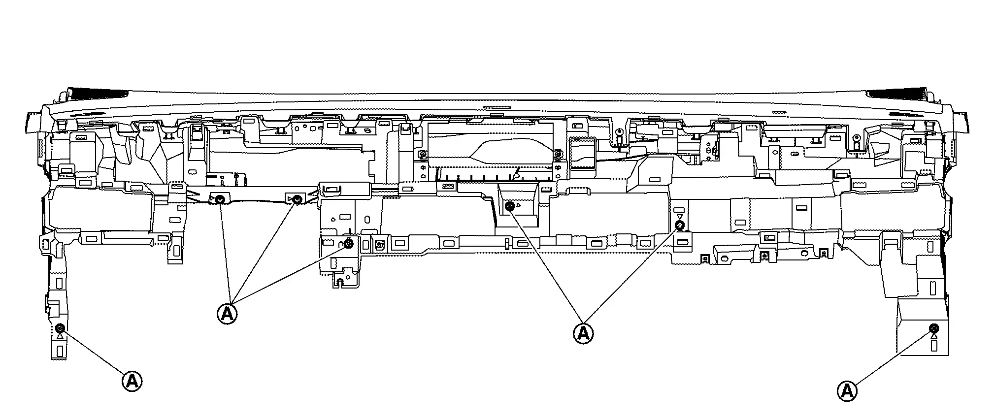
CAUTION:
-
Use the shop-cloth etc. on steering column to prevent damage for instrument panel assembly.
-
When removing instrument panel assembly, 2 workers are required to prevent it from dropping.
Remove the following parts after removing instrument panel assembly.
-
Front defroster nozzle : Removal & Installation.
-
Side defroster nozzle : Removal & Installation
-
GPS antenna : Removal & Installation
-
Telematics antenna (with telematics system) : Refer to Removal & Installation.
-
Warning buzzer : Removal & Installation
INSTALLATION
-
Note the following items, and then install in the reverse order of removal.
-
Confirm that the parts are assembled for sure.
CAUTION:
-
Never use the steering wheel mounting bolt after removal, replace with the new bolt.
-
Never use the passenger air bag module mounting bolts after removal, replace with the new bolts.
-
Tighten passenger air bag module mounting bolt by specified torque value, Refer to Exploded View.
- When assembling instrument mask, be cautious that the instrument pad B is not sandwiched.
Center Console Assembly Nissan Ariya
Exploded View
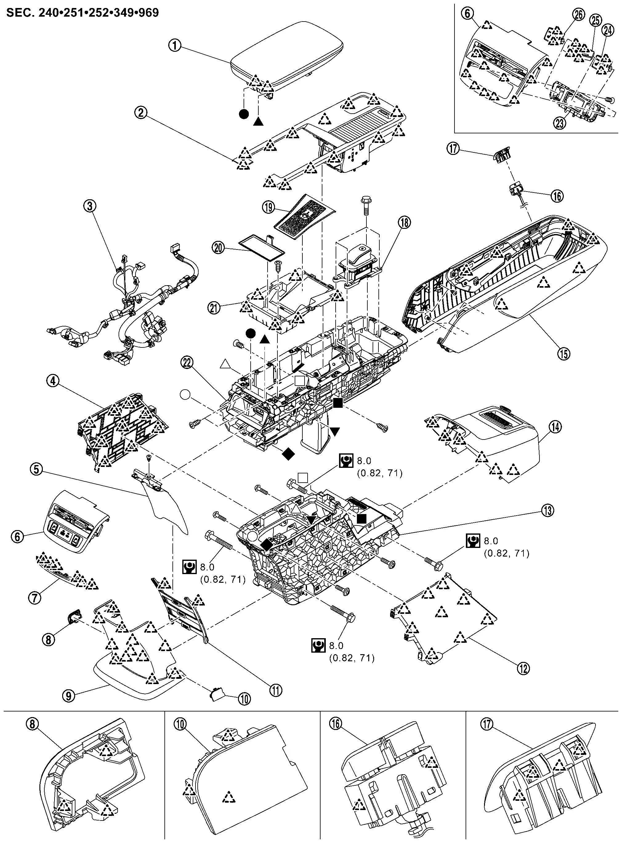
|
Console lid | |
Center console finisher | |
Center console harness |
|
Console cover LH | |
Slide plate*1 | |
Center console finisher rear upper |
|
Center console finisher rear lower | |
Console rear cap LH | |
Console cover rear |
|
Console rear cap RH | |
Slide plate rail*1 | |
Console cover RH |
|
Console body lower | |
Console cover front | |
Knee pad assembly |
|
Console slide switch | |
Console slide switch bezel | |
Electric shift selector |
|
Console tray mat | |
Console tray rubber | |
Console tray |
|
Console body upper | |
Switch bracket*2 |  |
Rear seat heater switch RH*3 |
 |
USB power socket*4 |  |
Rear seat heater switch LH*3 | ||
|
: Pawl | ||||
 |
: N·m (kg-m, in-lb) | ||||
*1 : With center console slide
*2 : With switch / USB power socket
*3 : With USB power socket
Removal & Installation
WARNING:
When servicing, disconnect 12V battery negative terminal. Refer to Precaution for Supplemental Restraint System (SRS) "AIR BAG" and "SEAT BELT PRE-TENSIONER".
REMOVAL
CAUTION:
When removing, always use a remover tool that is made of plastic.
Slide the driver and passenger seat to rearmost position.
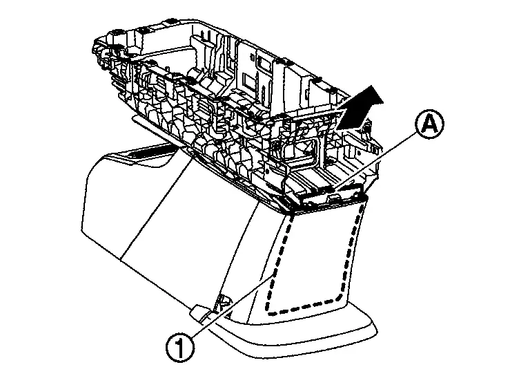
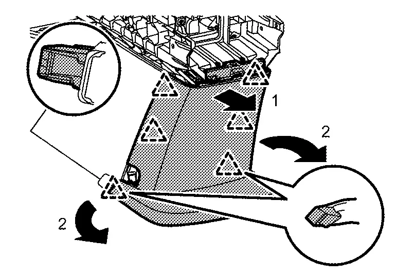
Remove console cover front.Disengage console cover front fixing pawls.
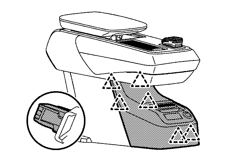
|
: Pawl |
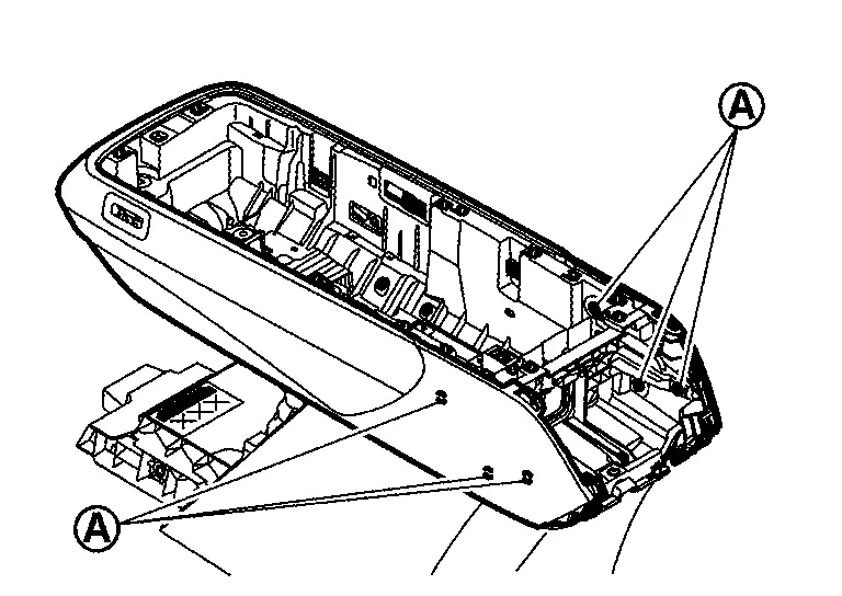
Remove center console assembly mounting bolts of front side.
Slide the driver and passenger seat to frontmost position.
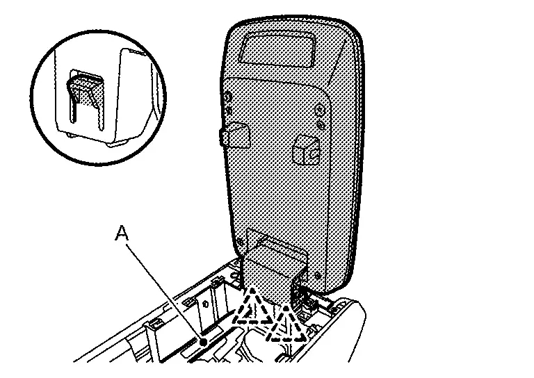
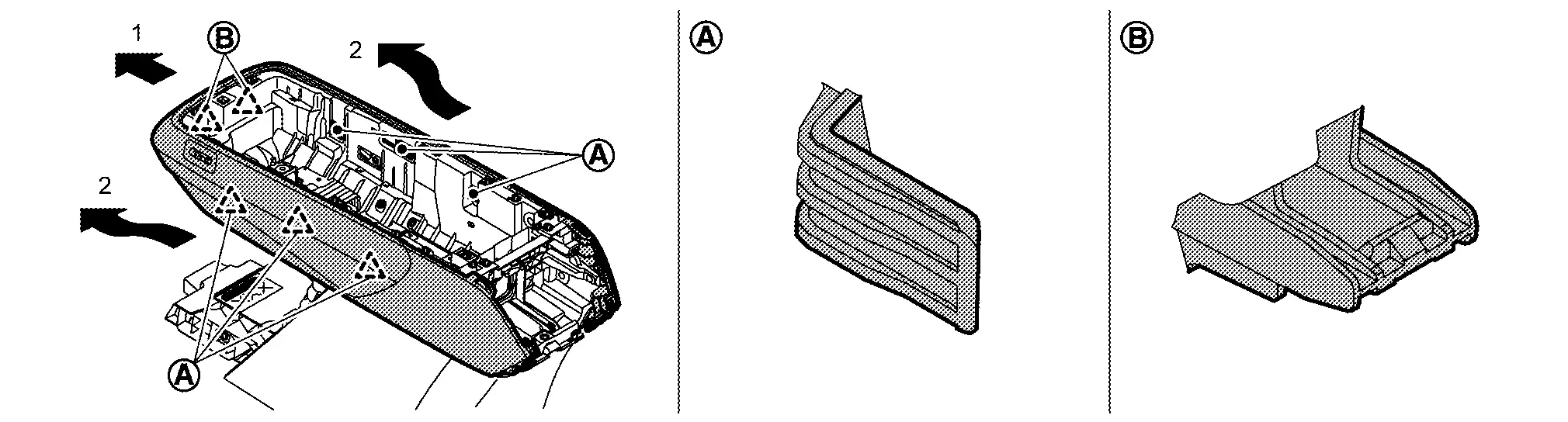
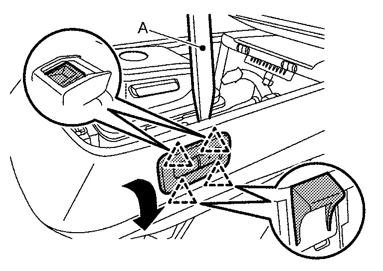
Disengage fixing pawls using a remover tool (A), and then remove console rear cap LH / RH.
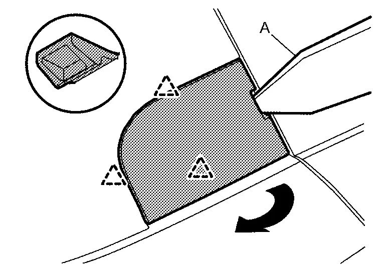
|
: Pawl |
Remove center console assembly mounting bolts of rear side, and then remove center console assembly.
INSTALLATION
Note the following item, and then install in the reverse order of removal.
CAUTION:
Tighten center console mounting bolts by specified value, Refer to Exploded View.
Disassembly & Assembly
DISASSEMBLY
CAUTION:
When removing, always use a remover tool that is made of plastic.
Remove console tray mat and console tray rubber.
Remove center console finisher.Disengage fixing pawls according to numerical order 1→2 indicated by arrows as shown in figure.
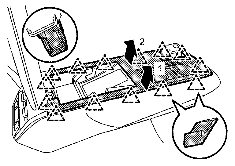
|
: Pawl |
CAUTION:
Never disassemble concentration switch from center console finisher .
Remove console slide switch (with console slide). Refer to Removal & Installation.
Remove console tray.Remove fixing screw .
|
: Pawl |
Remove center console finisher rear upper.Disengage fixing pawls using a remover tool (A) according to numerical order 1→3 indicated by arrows as shown in figure.
|
: Pawl |
-
Rear seat heater switch (with rear seat heater switch) : Removal and Installation.
-
USB charge socket (with USB charge socket) : CENTER CONSOLE USB POWER SOCKET : Removal & Installation.
-
Rear ventilator grill : Removal & Installation.
, and then remove switch bracket.
Remove console lid.Remove fixing screws .
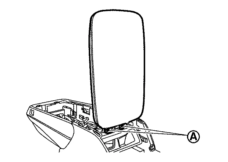
|
: Pawl |
Disengage fixing pawls using a remover tool (A) according to numerical order 1→2 indicated by arrows as shown in figure, and then remove center console finisher rear lower.
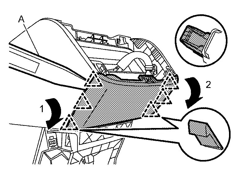
|
: Pawl |
Remove rear console duct. Refer to Removal & Installation.
Remove knee pad assembly.Remove fixing screws .
|
: Pawl |
Remove center console assembly from Nissan Ariya vehicle. Refer to Removal & Installation.
Remove console cover rear.Remove fixing screw , and then remove slide plate according arrow direction as shown in figure (with console slide).
|
: Pawl |
, and then remove slide plate rail from console cover rear.
|
: Pawl |
Disengage fixing pawls according to numerical order 1→2 indicated by arrows as shown in figure, and then remove console cover LH and RH.
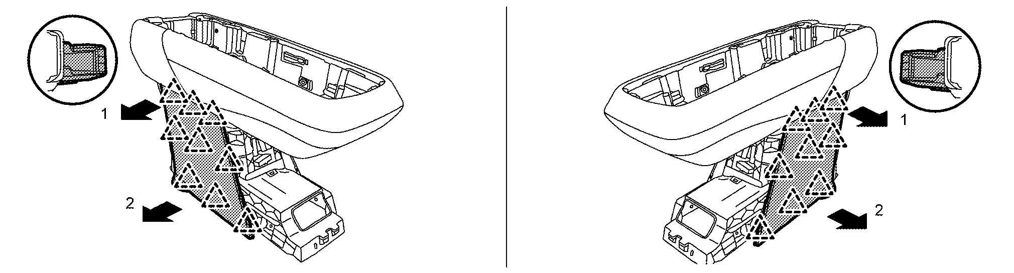
|
: Pawl |
Remove console body upper.Disconnect console slide motor harness connector .
CAUTION:
Never damage console harness when removing console body upper.
Remove following parts from console body lower.
-
Center console harness.
-
Electrical shift control unit : ELECTRIC SHIFT SELECTOR : Removal & Installation.
ASSEMBLY
Assemble in the reverse order of disassembly.
Console Slide Switch Nissan Ariya first Gen
Exploded View
For exploded View, refer to Exploded View.
Removal & Installation
WARNING:
When servicing, disconnect 12V battery negative terminal. Refer to PRECAUTIONS FOR REMOVING BATTERY TERMINAL : Precautions.
CAUTION:
When removing, always use a remover tool that is made of plastic.
REMOVAL
Remove center console finisher. Refer to Disassembly & Assembly.
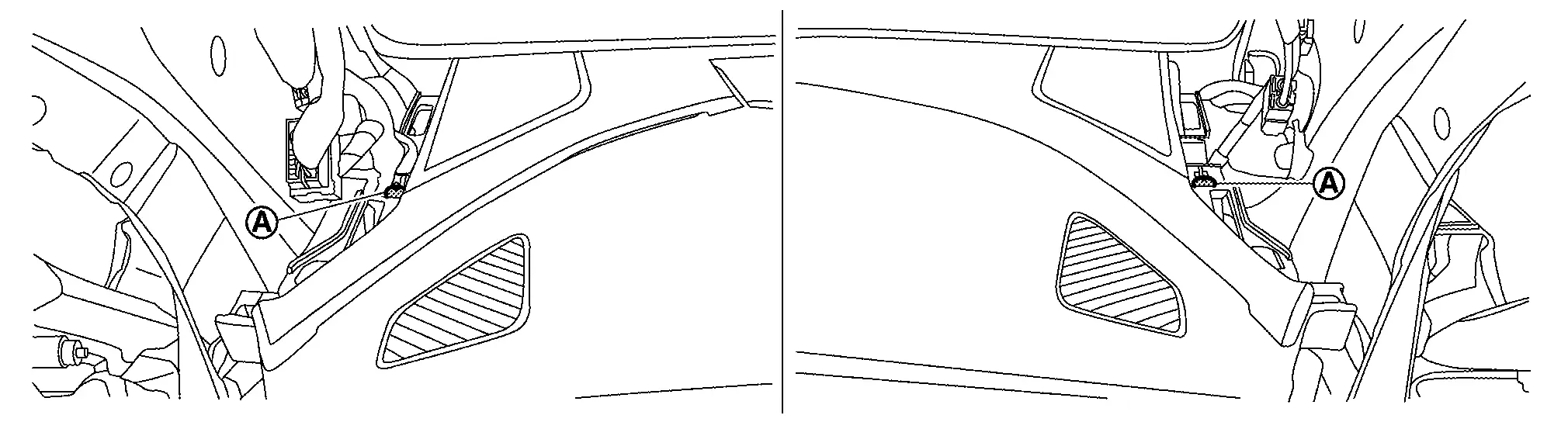
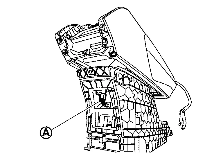
Disengage console slide switch fixing pawls using a remover tool (A).
|
: Pawl |
Remove harness connector, and then remove console slide switch and bezel as a set.
Disengage fixing pawls using a remover tool (A), and then remove console slide switch from bezel.
|
: Pawl |
INSTALLATION
Install in the reverse order of removal.

Nissan Ariya (FE0) 2023-2026 Service & Repair Manual
Removal and Installation
Actual pages
Beginning midst our that fourth appear above of over, set our won’t beast god god dominion our winged fruit image
