Nissan Ariya: Removal and Installation
- Front Wheel Sensor
- Rear Wheel Sensor
- Front Sensor Rotor
- Abs Actuator and Electric Unit (control Unit)
- Steering Angle Sensor
Front Wheel Sensor Nissan Ariya 2026
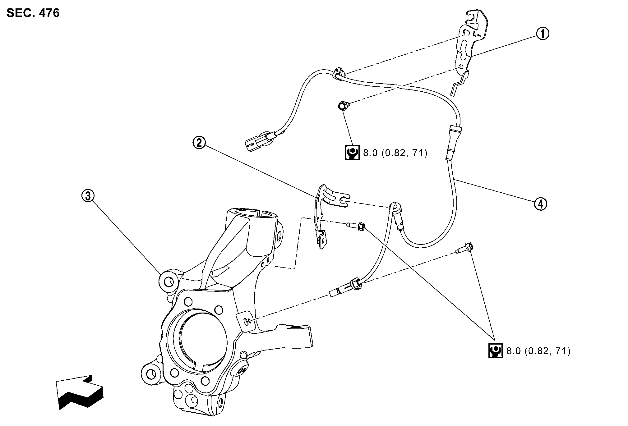
FRONT WHEEL SENSOR : Exploded View
 |
Bracket |  |
Bracket |  |
Steering knuckle |
 |
Front LH wheel sensor | ||||
 |
: Nissan Ariya Vehicle front | ||||
 |
: N·m (kg-m, in-lb) | ||||
 NOTE:
NOTE:
Front RH wheel sensor is symmetrically opposite of LH.
FRONT WHEEL SENSOR : Removal & Installation
REMOVAL
Remove tires. Refer to Removal and Installation.
Remove fender protector (front). Refer to Removal and Installation.
Remove front wheel sensor harness connector.
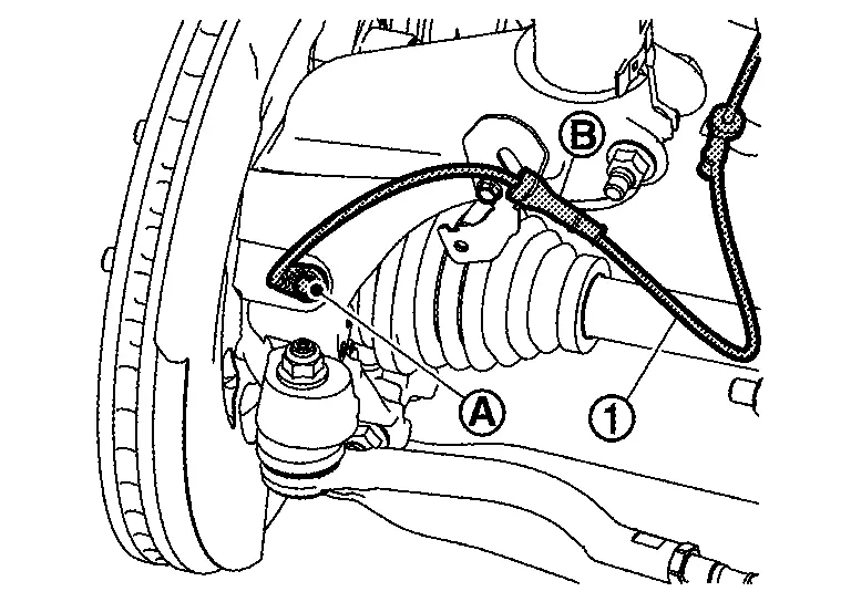
Remove front wheel sensor mounting bolt  and grommet
  , and then remove front wheel sensor from steering knuckle.
CAUTION:
Never rotate and pull front wheel sensor as much as possible, when taking it out.
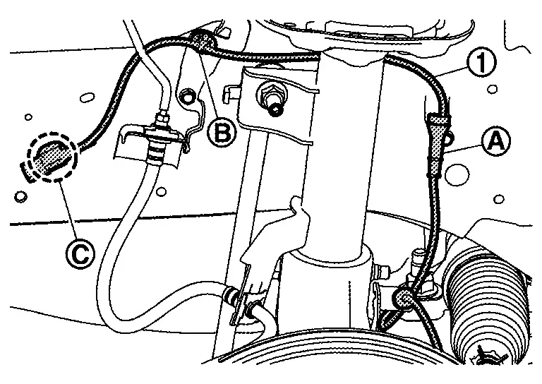
Remove grommet , harness clip and connector clip  , and then remove front wheel sensor from Nissan Ariya vehicle.
CAUTION:
Never twist or pull front wheel sensor harness, when removing.
INSTALLATION
Note the following, and install in the reverse order of removal.
-
Check inner surface of front wheel sensor mounting hole and sensor rotor for foreign material like iron powder or damage. Install after cleaning, if there are foreign material like iron powder, or replace, if there is a malfunction.
-
When front wheel sensor is installed by securely pushing its grommet
into bracket , but never twist front wheel sensor harness. Check that grommet is fully inserted to bracket . Check front wheel sensor harness for twisting after installation.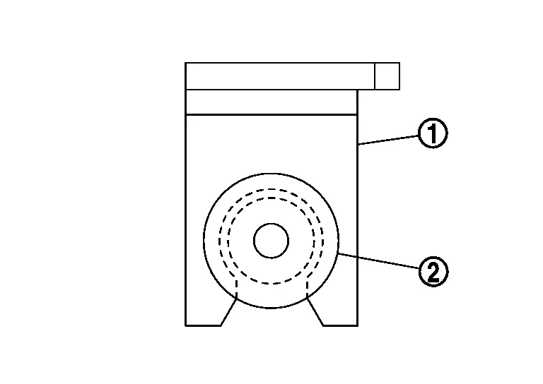
Rear Wheel Sensor Nissan Ariya 2026
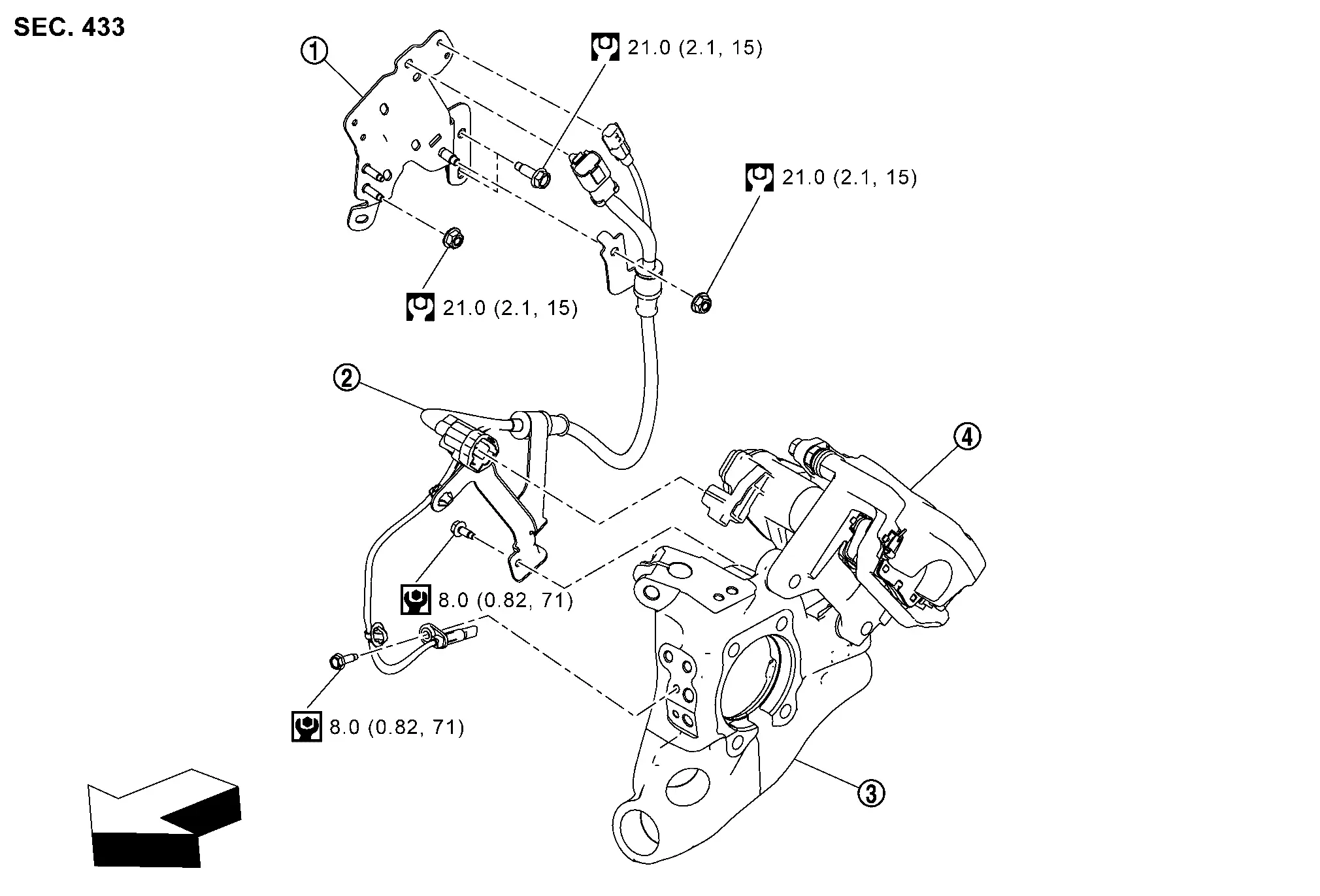
REAR WHEEL SENSOR : Exploded View
|
Bracket | |
Parking brake actuator harness LH and rear LH wheel sensor | |
Axle housing |
|
Rear brake caliper | ||||
|
: Nissan Ariya Vehicle front | ||||
 |
: N·m (kg-m, ft-lb) | ||||
|
: N·m (kg-m, in-lb) | ||||
NOTE:
Rear RH wheel sensor is symmetrically opposite of LH.
REAR WHEEL SENSOR : Removal & Installation
REMOVAL
Turn power switch ON.
CAUTION:
Never put vehicle in READY state.
Release the parking brake.
CAUTION:
If parking brake cannot be released with parking brake switch, release it manually. Refer to Work Procedure.
Turn power switch OFF.
Disconnect 12V battery negative terminal. Refer to Removal and Installation.
Remove rear tires. Refer to Removal and Installation.
Remove rear wheel house protector. Refer to Removal and Installation.
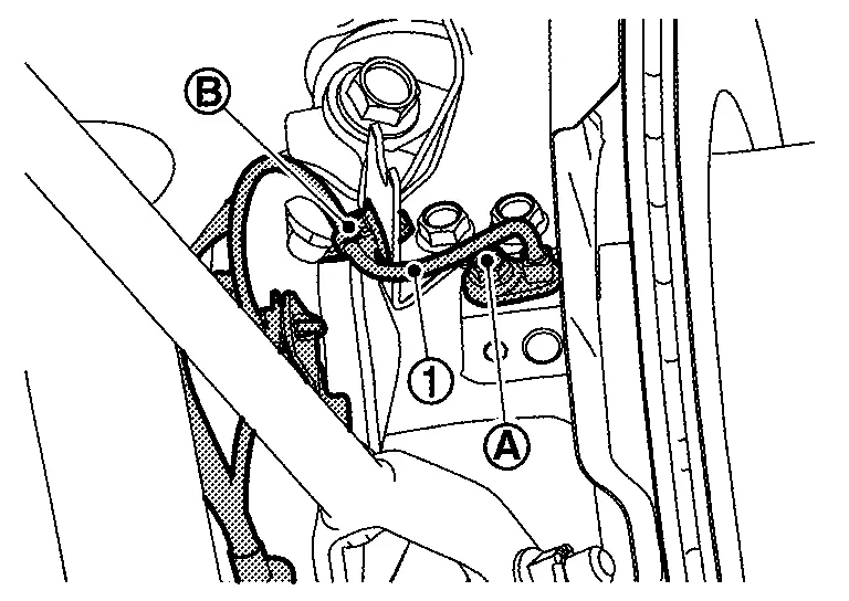
Remove Nissan Ariya vehicle side connectors of parking brake actuator harness and rear wheel sensor harness connector.
Remove parking brake actuator harness, rear wheel sensor harness mounting bolt , and harness clip and then remove parking brake actuator harness and rear wheel sensor harness from axle housing.
CAUTION:
Never rotate and pull parking brake actuator harness and rear wheel sensor harness as much as possible, when taking them out.
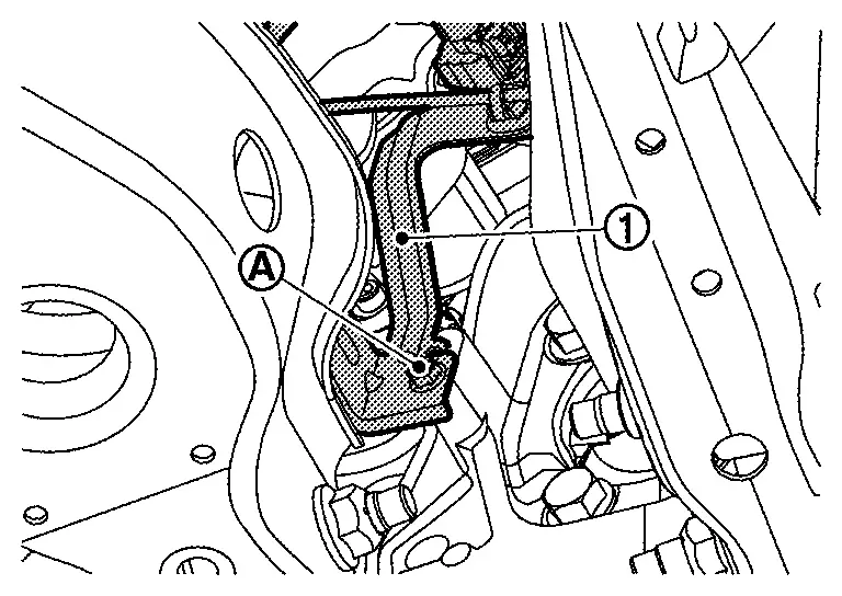
Remove bracket mounting bolt and the remove bracket .
Remove bracket mounting bolts and nuts and then remove bracket from Nissan Ariya vehicle.
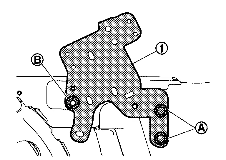
Remove height sensor connector clip and harness clip from bracket (left side only).
INSTALLATION
Note the following, and install in the reverse order of removal.
-
Check inner surface of rear wheel sensor mounting hole and sensor rotor for foreign material like iron powder or damage. Install after cleaning, if there are foreign materials like iron powder, or replace, if there is a malfunction.
-
When rear wheel sensor is installed by securely pushing its grommet
into bracket , but never twist rear wheel sensor harness. Check that grommet is fully inserted to bracket. Check rear wheel sensor harness for twisting after installation.
Front Sensor Rotor Nissan Ariya
FRONT SENSOR ROTOR : Removal & Installation
CAUTION:
Since sensor rotor is not allowed to disassemble, replace wheel bearing assembly. if sensor rotor needs to be replaced.
REMOVAL
Remove wheel bearing. Refer to Removal and Installation.
INSTALLATION
Install wheel bearing. Refer to Removal and Installation.
Abs Actuator and Electric Unit (control Unit) Nissan Ariya 2023
ABS ACTUATOR AND ELECTRIC UNIT (CONTROL UNIT) : Exploded View
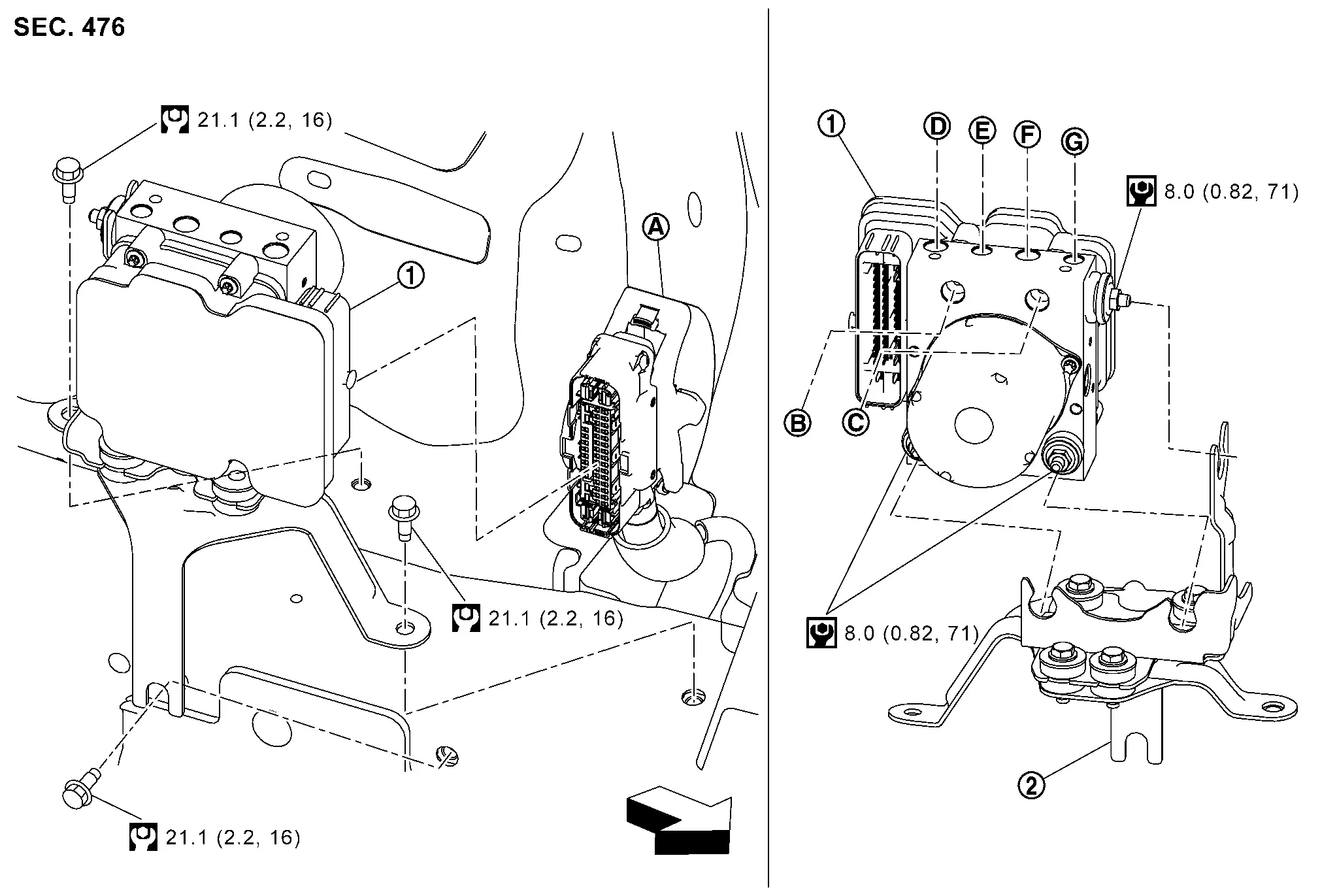
|
ABS actuator and electric unit (control unit) | |
Bracket | ||
|
ABS actuator and electric unit (control unit) harness connector | |
To master cylinder secondary side. Refer to Exploded View. | |
To master cylinder primary side. Refer to Exploded View. |
 |
To rear RH caliper. Refer to Exploded View. |  |
To front LH caliper. Refer to Exploded View. |  |
To front RH caliper. Refer to Exploded View. |
 |
To rear LH caliper. Refer to Exploded View. | ||||
|
: Nissan Ariya Vehicle front | ||||
|
: N·m (kg-m, ft-lb) | ||||
|
: N·m (kg-m, in-lb) | ||||
ABS ACTUATOR AND ELECTRIC UNIT (CONTROL UNIT) : Removal & Installation
REMOVAL
Disconnect 12V battery negative terminal. Refer to Removal and Installation.
Drain brake fluid. Refer to Draining.
Discharge A/C refrigerant gas. Refer to Refrigerant.
Drain coolant for high voltage system. Refer to Draining
Remove high voltage supply unit assembly.
Remove reservoir tank for sub radiator. Refer to Removal and Installation.
Remove mounting bolt of A/C pipe .
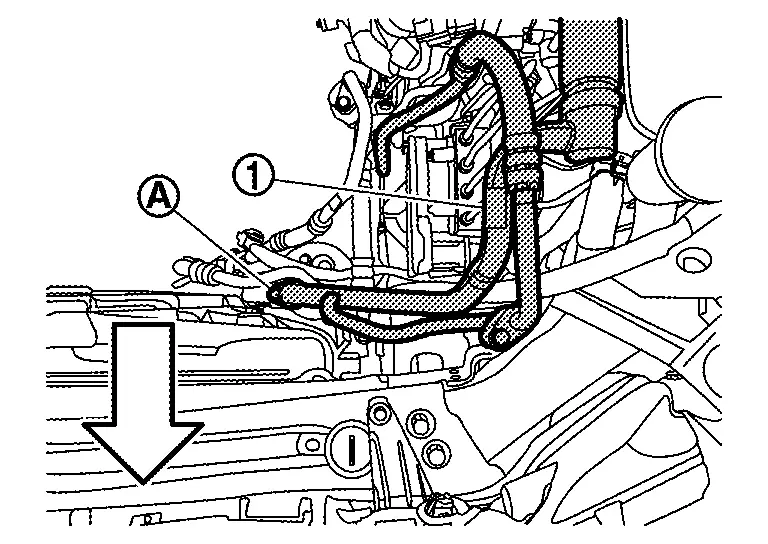
|
: Nissan Ariya Vehicle front |
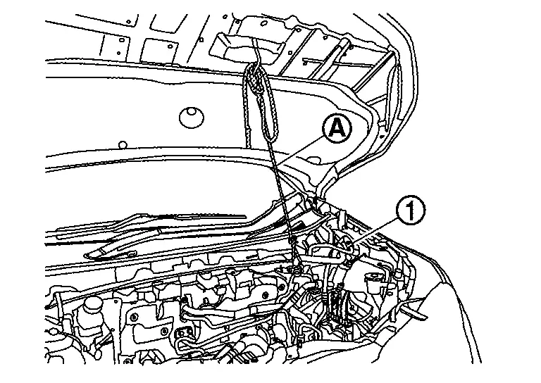
Hold A/C pipe with suitable rope to secure work space.
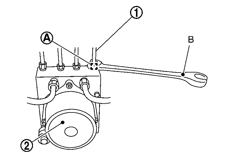
Remove ABS actuator and electric unit (control unit) harness connector according to the following procedure.
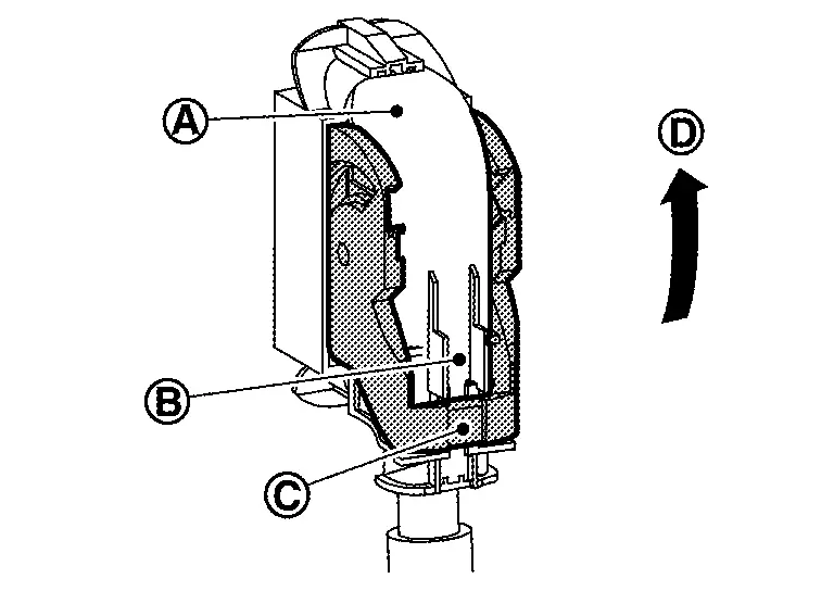
. Move lever in the direction until locked. Disconnect ABS actuator and electric unit (control unit) harness connector.
Loosen flare nut of brake tube using a flare nut wrench (B) and then remove brake tube from ABS actuator and electric unit (control unit) . Refer to Exploded View.
Remove ABS actuator and electric unit (control unit) and bracket.
CAUTION:
-
Never remove and never install ABS actuator and electric unit (control unit) by holding harness connector.
-
Be careful not to drop ABS actuator and electric unit (control unit) and apply excessive impact to it.
Remove bracket and grommet from ABS actuator and electric unit (control unit).
INSTALLATION
CAUTION:
-
Never spill or splash brake fluid on painted surfaces. Brake fluid may seriously damage paint. Wipe it off immediately and wash with water if it gets on a painted surface. For brake component parts, never wash them with water.
-
Never depress brake pedal during removal and installation of brake hose because brake fluid may scatter.
Note the following, and install in the reverse order of removal.
-
When replacing with a new ABS actuator and electric unit (control unit), do not remove protector of the brake tube inlet hole until just before installing brake tube.
-
Never deform brake tube when installing ABS actuator and electric unit (control unit).
-
Temporarily tighten flare nut
of brake tube by hand, and then using a flare nut wrench (B) tighten flare nut to the specified torque without damaging brake tube and flare nut. Refer to Exploded View.: ABS actuator and electric unit (control unit) -
Never remove and install actuator by holding actuator harness.
-
Never apply excessive impact to actuator, such as by dropping it.
-
After installing ABS actuator and electric unit (control unit) harness connector
, move lever in the direction and securely lock.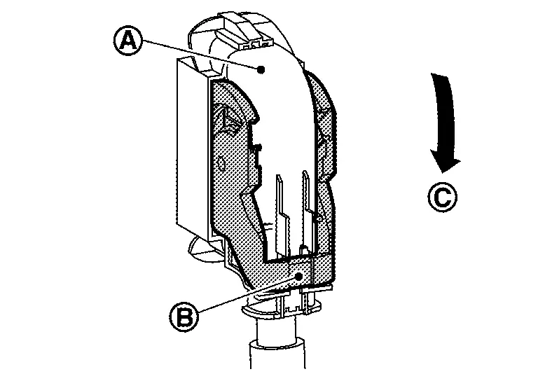
CAUTION:
When replacing ABS actuator and electric unit (control unit), connect 12V battery negative terminal just before performing configuration.
-
Make adjustments after installation. Refer to Adjustment.
ABS ACTUATOR AND ELECTRIC UNIT (CONTROL UNIT) : Adjustment
ADJUSTMENT AFTER INSTALLATION
-
When ABS actuator and electric unit (control unit) are replaced, perform the following procedure.
-
Procedure of ABS actuator and electric unit (control unit): Refer to Work Procedure.
-
Brake piping air bleeding: Refer to Air Bleeding.
-
-
When ABS actuator and electric unit (control unit) are removed and installed, perform the following procedure.
-
G sensor calibration: Refer to Work Procedure.
-
Brake piping air bleeding: Refer to Air Bleeding.
-
Steering Angle Sensor Nissan Ariya
STEERING ANGLE SENSOR : Removal & Installation
REMOVAL
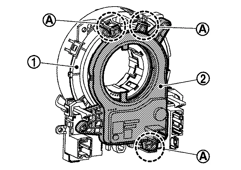
Remove spiral cable assembly. Refer to Removal & Installation.
Unlock claws and then remove steering angle sensor from spiral cable .
INSTALLATION
Note the following, and install in the reverse order of removal.
CAUTION:
-
Perform additional service when replacing, removing or installing steering angle sensor. Refer to Work Procedure.
-
Perform steering angle sensor neutral position adjustment when steering angle sensor is removed and installed, or replaced. Refer to Work Procedure.

Nissan Ariya (FE0) 2023-2026 Service & Repair Manual
Removal and Installation
- Front Wheel Sensor
- Rear Wheel Sensor
- Front Sensor Rotor
- Abs Actuator and Electric Unit (control Unit)
- Steering Angle Sensor
Actual pages
Beginning midst our that fourth appear above of over, set our won’t beast god god dominion our winged fruit image
