Nissan Ariya: Periodic Maintenance. Road Wheels & Tires
ROAD WHEEL TIRE : Adjustment
Aluminum Wheel
PREPARATION BEFORE ADJUSTMENT
Using releasing agent, remove double-faced adhesive tape from the road wheel.
CAUTION:
-
Never scratch the road wheel during removal.
-
After removing double-faced adhesive tape, wipe clean traces of releasing agent from the road wheel.
ADJUSTMENT
-
The details of the adjustment procedure are different for each model of wheel balancer. Therefore, refer to each instruction manual.
-
If a tire balance machine has adhesion balance weight mode settings and drive-in weight mode setting, select and adjust a drive-in weight mode suitable for aluminum wheels.
Set road wheel on tire balance machine using the center hole as a guide. Start the tire balance machine.
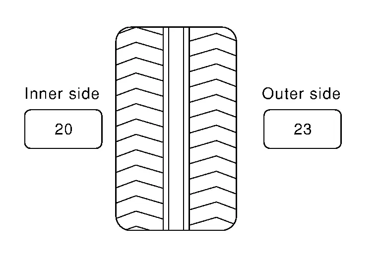
When inner and outer unbalance values are shown on the tire balance machine indicator, multiply outer unbalance value by 5/3 to determine balance weight that should be used. Select the outer balance weight with a value closest to the calculated value above and install to the designated outer position of, or at the designated angle in relation to the road wheel.
CAUTION:
-
Never install the inner balance weight before installing the outer balance weight.
-
Before installing the balance weight, always to clean the mating surface of the road wheel.
Calculation example:
23 g (0.81 oz) × 5/3 = 38.33 g (1.35 oz) ⇒ 40 g (1.41 oz) balance weight (closer to calculated balance weight value)
 NOTE:
NOTE:
Note that balance weight value must be closer to the calculated balance weight value.
Example:
37.4 ⇒ 35 g (1.23 oz)
37.5 ⇒ 40 g (1.41 oz)
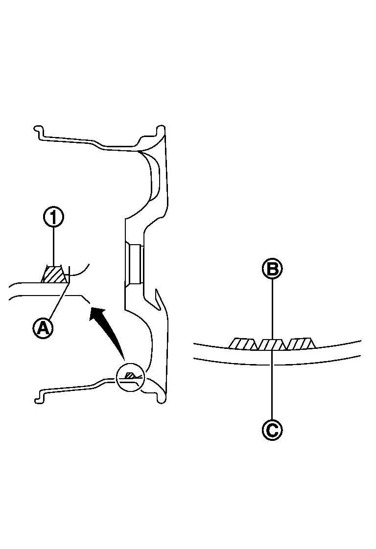
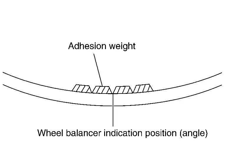
Installed balance weight in the position.-
When installing balance weight
 to road wheels, set it into the grooved area
  on the inner wall of the road wheel as shown in the figure so that the balance weight center
  is aligned with the tire balance machine indication position (angle)
  .
.
CAUTION:
-
Always use genuine NISSAN balance weights.
-
Balance weights are non-reusable; always replace with new ones.
-
Never install three or more sheets of balance weight.
-
CAUTION:
Never install one balance weight sheet on top of another.
Start the tire balance machine again.
Install drive-in balance weight on inner side of road wheel in the tire balance machine indication position (angle).
CAUTION:
Never install three or more balance weight.
Start the tire balance machine. Check that the inner and outer residual unbalance value is within the allowable unbalance value.
CAUTION:
If either residual unbalance value exceeds limit, repeat installation procedures.
| Allowable unbalance value | |
| Dynamic (At flange) | Refer to Service Data |
| Static (At flange) | Refer to Service Data |
ROAD WHEEL TIRE : Inspection
APPEARANCE
Road Wheel
-
Check road wheel for deformation, cracks, corrosion and other damage.
-
Check wheel nuts for looseness by using torque wrench.
Wheel nut tightening torque : Refer to Exploded View.
TIRE
-
Check entire circumference and both sides of each tire for deformation, cracks, scratch and other damage.
-
Check tire tread for wear and foreign matter such as nails and small rock.
-
Check that tire pressure is the specified value.
Tire pressure : Refer to Service Data
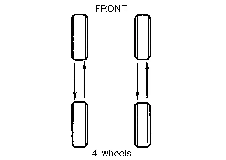
ROAD WHEEL TIRE : Rotation
-
Follow the maintenance schedule for tire rotation service intervals. Refer to General Maintenance.
-
When installing the wheel, tighten wheel nuts to the specified torque. Refer to Exploded View.
CAUTION:
-
Never include the T-type spare tire when rotating the tires.
-
When installing wheels, tighten them diagonally by dividing the work two to three times in order to prevent the wheels from developing any distortion.
-
Never tighten wheel nut at torque exceeding the criteria.
-
Use NISSAN genuine wheel nut.
-
-
After tire rotation, perform following:
-
Perform the ID registration.
-

Nissan Ariya (FE0) 2023-2026 Service & Repair Manual
Actual pages
Beginning midst our that fourth appear above of over, set our won’t beast god god dominion our winged fruit image
