Nissan Ariya: Dtc/circuit Diagnosis
- B2490-13 Front Seat Heater Lh
- B2490-19 Front Seat Heater Lh
- B2491-13 Seat Blower Motor Lh
- B2491-19 Seat Blower Motor Lh
- U1ca6-02 Front Seat Heater Rh Communication
- Power Supply and Ground Circuit
- Lumbar Support Switch
- Lumbar Support Pump
- Front Seat Heater Lh
- Rear Heated Seat Switch Lh
- Rear Heated Seat Switch Indicator Lh
- Seat Blower Motor Lh
B2490-13 Front Seat Heater Lh Nissan Ariya SUV
DTC Description
DTC DETECTION LOGIC
| DTC No. | CONSULT screen items | DTC detection condition | ||
|---|---|---|---|---|
| B2490-13 | Front seat heater LH | A | Diagnosis condition | Power switch ON and front heated seat switch LH ON |
| Signal (terminal) | — | |||
| Threshold | CPU inside the front seat heater LH detected a heater current of 0.2 A or less | |||
| Diagnosis delay time | 6 minuites or more | |||
| B | Diagnosis condition | Power switch ON and front heated seat switch LH ON | ||
| Signal (terminal) | — | |||
| Threshold | CPU inside the front seat heater LH detected heater sensor signal voltage of 4.94 V or more | |||
| Diagnosis delay time | 94 seconds or more | |||
POSSIBLE CAUSE
Front seat cushion heater LH
FAIL-SAFE
Front seat heater LH operation is stopped
DTC CONFIRMATION PROCEDURE
PERFORM DTC CONFIRMATION PROCEDURE
 With CONSULT
-
Power switch ON.
-
Front heated seat switch LH ON and wait at least 6 minutes or more.
-
Check “Self Diagnostic Result” of “HVAC” using CONSULT.
Is DTC detected?
YES>>Refer to Diagnosis Procedure.
NO-1 >>To check malfunction symptom before repair: Refer to Intermittent Incident.
NO-2 >>Confirmation after repair: INSPECTION END
Diagnosis Procedure
REPLACE SEAT CUSHION PAD
Replace seat cushion pad. Refer to Disassembly & Assembly.
>>
INSPECTION END
B2490-19 Front Seat Heater Lh Nissan Ariya SUV
DTC Description
DTC DETECTION LOGIC
| DTC No. | CONSULT screen items | DTC detection condition | ||
|---|---|---|---|---|
| B2490-19 | Front seat heater LH | A | Diagnosis condition | Power switch ON and front heated seat switch LH ON |
| Signal (terminal) | — | |||
| Threshold | CPU inside the front seat heater LH detected a heater current of 14 A or more | |||
| Diagnosis delay time | 2 seconds or more | |||
| B | Diagnosis condition | Power switch ON and front heated seat switch LH ON | ||
| Signal (terminal) | — | |||
| Threshold | CPU inside the front seat heater LH detected a heater sensor signal voltage of 0.31 V or less | |||
| Diagnosis delay time | 4 minuites or more | |||
| C | Diagnosis condition | Power switch ON and front heated seat switch LH ON | ||
| Signal (terminal) | — | |||
| Threshold | CPU inside the front seat heater LH counted 15,000 errors | |||
| Diagnosis delay time | — | |||
POSSIBLE CAUSE
-
Front seat cushion heater LH
-
Front seatback heater LH
FAIL-SAFE
Front seat heater LH operation is stopped
DTC CONFIRMATION PROCEDURE
PERFORM DTC CONFIRMATION PROCEDURE
With CONSULT
-
Power switch ON.
-
Front heated seat switch LH ON and wait at least 4 minutes or more.
-
Check “Self Diagnostic Result” of “HVAC” using CONSULT.
Is DTC detected?
YES>>Refer to Diagnosis Procedure.
NO-1 >>To check malfunction symptom before repair: Refer to Intermittent Incident.
NO-2 >>Confirmation after repair: INSPECTION END
Diagnosis Procedure
CHECK FRONT SEATBACK HEATER LH
Check front seatback heater LH. Refer to Component Inspection.
Is the inspection result normal?
YES>>Replace seat cushion pad. Refer to Disassembly & Assembly.
NO>>Replace seatback assembly. Refer to Disassembly & Assembly.
Component Inspection
CHECK FRONT SEATBACK HEATER LH
-
Power switch OFF.
-
Disconnect front seatback heater LH connector.
-
Check resistance between front seatback heater LH terminals.
Front seatback heater LH Resistance Terminal 2 1 4.61 – 5.63 Ω
Is the inspection result normal?
YES>>INSPECTION END
NO>>Replace seatback assembly. Refer to Disassembly & Assembly.
B2491-13 Seat Blower Motor Lh Nissan Ariya 2023
DTC Description
DTC DETECTION LOGIC
| DTC No. | CONSULT screen items | DTC detection condition | |
|---|---|---|---|
| B2491-13 | Seat blower motor LH | Diagnosis condition | Power switch ON and front ventilation seat switch LH ON |
| Signal (terminal) | — | ||
| Threshold | CPU inside the front seat heater LH detected a seat blower motor current of 0.112 A or less | ||
| Diagnosis delay time | 2 seconds or more | ||
POSSIBLE CAUSE
-
Front seat cushion blower motor LH
-
Front seat cushion heater LH
FAIL-SAFE
Seat blower motor LH operation is stopped
DTC CONFIRMATION PROCEDURE
PERFORM DTC CONFIRMATION PROCEDURE
With CONSULT
-
Power switch ON.
-
Front ventilation seat switch LH ON and wait at least 2 minutes or more.
-
Check “Self Diagnostic Result” of “HVAC” using CONSULT.
Is DTC detected?
YES>>Refer to Diagnosis Procedure.
NO-1 >>To check malfunction symptom before repair: Refer to Intermittent Incident.
NO-2 >>Confirmation after repair: INSPECTION END
Diagnosis Procedure
REPLACE SEAT CUSHION PAD
Replace seat cushion pad. Refer to Disassembly & Assembly.
>>
INSPECTION END
B2491-19 Seat Blower Motor Lh Nissan Ariya SUV
DTC Description
DTC DETECTION LOGIC
| DTC No. | CONSULT screen items | DTC detection condition | ||
|---|---|---|---|---|
| B2491-19 | Seat blower motor LH | A | Diagnosis condition | Power switch ON and front ventilation seat switch LH ON |
| Signal (terminal) | — | |||
| Threshold | CPU inside the front seat heater LH detected a seat blower motor current of 4.52 A or more | |||
| Diagnosis delay time | 2 seconds or more | |||
| B | Diagnosis condition | Power switch ON and front ventilation seat switch LH ON | ||
| Signal (terminal) | — | |||
| Threshold | CPU inside the front seat heater LH detected a seat blower motor speed control signal voltage of 1.0 V or less | |||
| Diagnosis delay time | 1.5 seconds or more | |||
POSSIBLE CAUSE
-
Front seat cushion blower motor LH
-
Front seatback blower motor LH
-
Front seat cushion heater LH
FAIL-SAFE
Seat blower motor LH operation is stopped
DTC CONFIRMATION PROCEDURE
PERFORM DTC CONFIRMATION PROCEDURE
With CONSULT
-
Power switch ON.
-
Front ventilation seat switch LH ON and wait at least 2 seconds or more.
-
Check “Self Diagnostic Result” of “HVAC” using CONSULT.
Is DTC detected?
YES>>Refer to Diagnosis Procedure.
NO-1 >>To check malfunction symptom before repair: Refer to Intermittent Incident.
NO-2 >>Confirmation after repair: INSPECTION END
Diagnosis Procedure
PERFORM DTC CONFIRMATION PROCEDURE
With CONSULT
-
Power switch OFF.
-
Disconnect seatback blower motor LH connector.
-
Power switch ON.
-
Front ventilation seat switch LH ON and wait at least 2 seconds or more.
-
Check “Self Diagnostic Result” of “HVAC” using CONSULT.
Is DTC detected?
YES>>Replace seat cushion pad. Refer to Disassembly & Assembly.
NO>>Replace seatback blower motor. Refer to Removal and Installation.
U1ca6-02 Front Seat Heater Rh Communication Nissan Ariya: FE0
DTC Description
DTC DETECTION LOGIC
| DTC No. | CONSULT screen items | DTC detection condition | |
|---|---|---|---|
| U1CA6-02 | Front seat heater RH communication | Diagnosis condition | Power switch ON |
| Signal (terminal) | LIN (heated seat) signal (terminal #45) | ||
| Threshold | A/C auto amp. is not transmitting or receiving LIN communication with front seat heater RH | ||
| Diagnosis delay time | 30 seconds or more | ||
POSSIBLE CAUSE
-
Fuse
-
Harness or connectors (Front seat heater RH circuit is open or short to ground)
-
Front seat cushion heater RH
-
A/C auto amp.
FAIL-SAFE
—
DTC CONFIRMATION PROCEDURE
PERFORM DTC CONFIRMATION PROCEDURE
With CONSULT
-
Power switch ON and wait at least 30 seconds or more.
-
Check “Self Diagnostic Result” of “HVAC” using CONSULT.
Is DTC detected?
YES>>Refer to Diagnosis Procedure.
NO-1 >>To check malfunction symptom before repair: Refer to Intermittent Incident.
NO-2 >>Confirmation after repair: INSPECTION END
Diagnosis Procedure
CHECK FUSE
-
Power switch OFF.
-
Check that the following fuse is not blown (open).
Signal name Fuse No. Front seat heater RH power supply 83 (15A)
Is the fuse blown (open)?
YES>>Replace the blown (open) fuse after repairing the affected circuit if a fuse is blown (open).
NO>>GO TO 2.
CHECK FRONT SEAT HEATER RH POWER SUPPLY VOLTAGE
-
Disconnect front seat heater RH connector.
-
Power switch ON.
-
Check voltage between front seat heater RH harness connector and ground.
+ - Voltage Front seat heater RH Connector Terminal B470 1 Ground Battery voltage
Is the inspection result normal?
YES>>GO TO 3.
NO>>Repair the front seat heater RH power supply circuit.
CHECK FRONT SEAT HEATER RH GROUND CIRCUIT (OPEN)
-
Power switch OFF.
-
Check continuity between front seat heater RH harness connector and ground.
Front seat heater RH ー Continuity Connector Terminal B470 4 Ground Existed
Is the inspection result normal?
YES>>GO TO 4.
NO>>Repair the harness or connector.
CHECK FRONT SEAT HEATER RH LIN SIGNAL
-
Power switch ON.
-
Confirm output waveform between front seat heater RH harness connector and A/C auto amp. harness connector with oscilloscope.
+ – Output waveform Front seat heater RH A/C auto amp. Connector Terminal Connector Terminal B470 3 M1 58 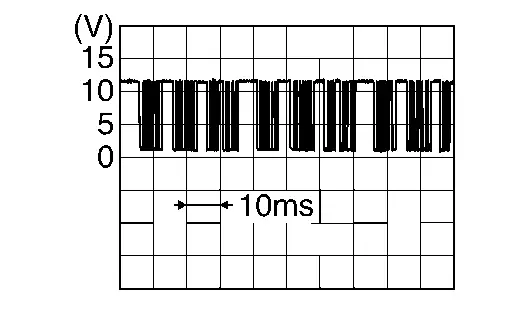
Is the inspection result normal?
YES>>Replace seat cushion pad. Refer to Disassembly & Assembly.
NO>>GO TO 5.
CHECK FRONT SEAT HEATER RH LIN SIGNAL CIRCUIT (OPEN)
-
Power switch OFF.
-
Disconnect A/C auto amp. connector.
-
Check continuity between front seat heater RH harness connector and A/C auto amp. harness connector.
Front seat heater RH A/C auto amp. Continuity Connector Terminal Connector Terminal B470 3 M1 45 Existed
Is the inspection result normal?
YES>>GO TO 6.
NO>>Repair the harness or connector.
CHECK FRONT SEAT HEATER RH LIN SIGNAL CIRCUIT (SHORT TO GROUND)
-
Disconnect the following connectors that are connected to terminal 45 of the A/C auto amp.
-
Front seat heater LH
-
Rear seat heater LH
-
Rear seat heater RH
-
Humidity sensor
-
-
Check continuity between front seat heater RH harness connector and ground.
Front seat heater RH — Continuity Connector Terminal B470 3 Ground Not existed
Is the inspection result normal?
YES>>Replace A/C auto amp. Refer to Removal & Installation.
NO>>Repair the harness or connector.
Power Supply and Ground Circuit Nissan Ariya 2026
Diagnosis Procedure
CHECK FUSE
-
Power switch OFF.
-
Check that the following fuse is not blown (open).
Signal name Fuse No. Battery power supply 58 (20A)
Is the fuse blown (open)?
YES>>Replace the blown (open) fuse after repairing the affected circuit if a fuse is blown (open).
NO>>GO TO 2.
CHECK DRIVER LUMBAR SUPPORT CONTROL MODULE BATTERY POWER SUPPLY VOLTAGE
-
Disconnect driver lumbar support control module connector.
-
Check voltage between driver lumbar support control module harness connector and ground.
+ - Voltage Driver lumbar support control module Connector Terminal B724 1 Ground Battery voltage
Is the inspection result normal?
YES>>GO TO 3.
NO>>Repair the driver lumbar support control module battery power supply circuit.
CHECK DRIVER LUMBAR SUPPORT CONTROL MODULE GROUND CIRCUIT (OPEN)
Check continuity between driver lumbar support control module harness connector and ground.
| Driver lumbar support control module | — | Continuity | |
|---|---|---|---|
| Connector | Terminal | ||
| B724 | 10 | Ground | Existed |
Is the inspection result normal?
YES>>INSPECTION END
NO>>Repair the harness or connector.
Lumbar Support Switch Nissan Ariya 2026
Component Function Check
CHECK LUMBAR SUPPORT SWITCH FUNCTION
Operate the lumbar support switch and check that the seatback support operates.
Is the inspection result normal?
YES>>Lumbar support switch is OK.
NO>>Refer to Diagnosis Procedure.
Diagnosis Procedure
CHECK LUMBAR SUPPORT SWITCH POWER SUPPLY VOLTAGE
-
Power switch OFF.
-
Disconnect lumbar support switch connector.
-
Check voltage between lumbar support switch harness connector and ground.
+ - Voltage
(Approx.)Lumbar support switch Connector Terminal B725 80 Ground 12.5 V
Is the inspection result normal?
YES>>GO TO 4.
NO>>GO TO 2.
CHECK LUMBAR SUPPORT SWITCH SIGNAL CIRCUIT (OPEN)
-
Disconnect driver lumbar support control module connector.
-
Check continuity between lumbar support switch harness connector and driver lumbar support control module harness connector.
Lumbar support switch Driver lumbar support control module Continuity Connector Terminal Connector Terminal B725 80 B724 80 Existed
Is the inspection result normal?
YES>>GO TO 3.
NO>>Repair the harness or connector.
CHECK LUMBAR SUPPORT SWITCH SIGNAL CIRCUIT (SHORT TO GROUND)
Check continuity between lumbar support switch harness connector and ground.
| Lumbar support switch | — | Continuity | |
|---|---|---|---|
| Connector | Terminal | ||
| B725 | 80 | Ground | Not existed |
Is the inspection result normal?
YES>>Replace lumbar support unit. Refer to Disassembly & Assembly.
NO>>Repair the harness or connector.
CHECK LUMBAR SUPPORT SWITCH GROUND CIRCUIT (OPEN)
-
Disconnect driver lumbar support control module connector.
-
Check continuity between lumbar support switch harness connector and driver lumbar support control module harness connector.
Lumbar support switch Driver lumbar support control module Continuity Connector Terminal Connector Terminal B725 81 B724 81 Existed
Is the inspection result normal?
YES>>GO TO 5.
NO>>Repair the harness or connector.
CHECK LUMBAR SUPPORT SWITCH
Check lumbar support switch. Refer to Component Inspection.
Is the inspection result normal?
YES>>Replace lumbar support unit. Refer to Disassembly & Assembly.
NO>>Replace lumbar support switch. Refer to Removal and Installation.
Component Inspection
CHECK LUMBAR SUPPORT SWITCH
-
Power switch OFF.
-
Disconnect lumbar support switch connector.
-
Check resistance between lumbar support switch terminals.
Lumbar support switch Condition Resistance: kΩ Terminal 80 81 Lumbar support switch Operate (upward) 3.855 – 4.217 Operate (downward) 1.440 – 1.622 Operate (forward) 0.640 – 0.742 Operate (backward) 0.241 – 0.287 Release ∞
Is the inspection result normal?
YES>>INSPECTION END
NO>>Replace lumbar support switch. Refer to Removal and Installation.
Lumbar Support Pump Nissan Ariya SUV
Component Function Check
CHECK LUMBAR SUPPORT PUMP FUNCTION
Operate the lumbar support switch forward / upward / downward, and check from the sound that the lumbar support pump operates.
Is the inspection result normal?
YES>>Lumbar support pump is OK
NO>>Refer to Diagnosis Procedure.
Diagnosis Procedure
CHECK LUMBAR SUPPORT PUMP POWER SUPPLY VOLTAGE
-
Power switch OFF.
-
Disconnect lumbar support pump connector.
-
Check voltage between lumbar support pump harness connector and ground.
+ - Condition Voltage
(Approx.)Lumbar support pump Connector Terminal B726 82 Ground Lumbar support Forward/upward/downward 12 V
Is the inspection result normal?
YES>>GO TO 4.
NO>>GO TO 2.
CHECK LUMBAR SUPPORT PUMP POWER SUPPLY CIRCUIT (OPEN)
-
Disconnect driver lumbar support control module connector.
-
Check continuity between lumbar support pump harness connector and driver lumbar support control module harness connector.
Lumbar support pump Driver lumbar support control module Continuity Connector Terminal Connector Terminal B726 82 B724 82 Existed
Is the inspection result normal?
YES>>GO TO 3.
NO>>Repair the harness or connector.
CHECK LUMBAR SUPPORT PUMP POWER SUPPLY CIRCUIT (SHORT TO GROUND)
Check continuity between lumbar support pump harness connector and ground.
| Lumbar support pump | — | Continuity | |
|---|---|---|---|
| Connector | Terminal | ||
| B726 | 82 | Ground | Not existed |
Is the inspection result normal?
YES>>Replace lumbar support unit. Refer to Disassembly & Assembly.
NO>>Repair the harness or connector.
CHECK LUMBAR SUPPORT PUMP GROUND CIRCUIT
-
Disconnect driver lumbar support control module connector.
-
Check continuity between lumbar support pump harness connector and driver lumbar support control module harness connector.
Lumbar support pump Driver lumbar support control module Continuity Connector Terminal Connector Terminal B726 83 B724 83 Existed
Is the inspection result normal?
YES>>Replace lumbar support unit. Refer to Disassembly & Assembly.
NO>>Repair the harness or connector.
Front Seat Heater Lh Nissan Ariya SUV
Component Function Check
CHECK FRONT SEAT HEATER LH FUNCTION
-
Power switch ON.
-
Check that seat cushion and seatback of front seat LH warms when operating front heated seat switch LH.
Is the inspection result normal?
YES>>Front seat heater LH is OK.
NO>>Refer to Diagnosis Procedure.
Diagnosis Procedure
CHECK FUSE
-
Power switch OFF.
-
Check that the following fuse is not blown (open).
Signal name Fuse No. Front seat heater LH power supply 84 (15A)
Is the fuse blown (open)?
YES>>Replace the blown (open) fuse after repairing the affected circuit if a fuse is blown (open).
NO>>GO TO 2.
CHECK FRONT SEAT HEATER LH POWER SUPPLY VOLTAGE
-
Disconnect front seat heater LH connector.
-
Power switch ON.
-
Check voltage between front seat heater LH harness connector and ground.
+ - Voltage Front seat heater LH Connector Terminal B472 1 Ground Battery voltage
Is the inspection result normal?
YES>>GO TO 3.
NO>>Repair the front seat heater LH power supply circuit.
CHECK FRONT SEAT HEATER LH GROUND CIRCUIT (OPEN)
-
Power switch OFF.
-
Check continuity between front seat heater LH harness connector and ground.
Front seat heater LH ー Continuity Connector Terminal B472 4 Ground Existed
Is the inspection result normal?
YES>>GO TO 4.
NO>>Repair the harness or connector.
CHECK FRONT SEAT HEATER LH LIN SIGNAL
-
Power switch ON.
-
Confirm output waveform between front seat heater LH harness connector and A/C auto amp. harness connector with oscilloscope.
+ – Output waveform Front seat heater LH A/C auto amp. Connector Terminal Connector Terminal B472 3 M1 58
Is the inspection result normal?
YES>>GO TO 7.
NO>>GO TO 5.
CHECK FRONT SEAT HEATER LH LIN SIGNAL CIRCUIT (OPEN)
-
Power switch OFF.
-
Disconnect A/C auto amp. connector.
-
Check continuity between front seat heater LH harness connector and A/C auto amp. harness connector.
Front seat heater LH A/C auto amp. Continuity Connector Terminal Connector Terminal B472 3 M1 45 Existed
Is the inspection result normal?
YES>>GO TO 6.
NO>>Repair the harness or connector.
CHECK FRONT SEAT HEATER LH LIN SIGNAL CIRCUIT (SHORT TO GROUND)
-
Disconnect the following connectors that are connected to terminal 45 of the A/C auto amp.
-
Front seat heater RH
-
Rear seat heater LH
-
Rear seat heater RH
-
Humidity sensor
-
-
Check continuity between front seat heater LH harness connector and ground.
Front seat heater LH — Continuity Connector Terminal B472 3 Ground Not existed
Is the inspection result normal?
YES>>Replace A/C auto amp. Refer to Removal & Installation.
NO>>Repair the harness or connector.
CHECK FRONT SEATBACK HEATER LH
Check front seatback heater LH. Refer to Component Inspection.
Is the inspection result normal?
YES>>Replace seat cushion pad. Refer to Disassembly & Assembly.
NO>>Replace seatback assembly. Refer to Disassembly & Assembly.
Component Inspection
CHECK FRONT SEATBACK HEATER LH
-
Power switch OFF.
-
Disconnect front seatback heater LH connector.
-
Check resistance between front seatback heater LH terminals.
Front seatback heater LH Resistance Terminal 2 1 4.61 – 5.63 Ω
Is the inspection result normal?
YES>>INSPECTION END
NO>>Replace seatback assembly. Refer to Disassembly & Assembly.
Rear Heated Seat Switch Lh Nissan Ariya
Component Function Check
CHECK REAR HEATED SEAT SWITCH LH FUNCTION
-
Set the Nissan Ariya vehicle to READY.
-
Check that rear heated seat switch LH indicator (Low, Mid, High) turns ON when operating rear heated seat switch LH.
Is the inspection result normal?
YES>>Rear heated seat switch LH is OK.
NO>>Refer to Diagnosis Procedure.
Diagnosis Procedure
CHECK REAR HEATED SEAT SWITCH LH POWER SUPPLY VOLTAGE
-
Power switch OFF.
-
Disconnect rear heated seat switch LH connector.
-
Power switch ON.
-
Check voltage between rear heated seat switch LH harness connector and ground.
+ - Voltage
(Approx.)Rear heated seat switch LH Connector Terminal M209 5 Ground 12 V
Is the inspection result normal?
YES>>GO TO 4.
NO>>GO TO 2.
CHECK REAR HEATED SEAT SWITCH LH SIGNAL CIRCUIT (OPEN)
-
Power switch OFF.
-
Disconnect A/C control connector.
-
Check continuity between rear heated seat switch LH harness connector and A/C control harness connector.
Rear heated seat switch LH A/C control Continuity Connector Terminal Connector Terminal M209 5 M69 8 Existed
Is the inspection result normal?
YES>>GO TO 3.
NO>>Repair the harness or connector.
CHECK REAR HEATED SEAT SWITCH LH SIGNAL CIRCUIT (SHORT TO GROUND)
Check continuity between rear heated seat switch LH harness connector and ground.
| Rear heated seat switch LH | — | Continuity | |
|---|---|---|---|
| Connector | Terminal | ||
| M209 | 5 | Ground | Not existed |
Is the inspection result normal?
YES>>Replace A/C control. Refer to Removal & Installation.
NO>>Repair the harness or connector.
CHECK REAR HEATED SEAT SWITCH LH GROUND CIRCUIT (OPEN)
-
Power switch OFF.
-
Check continuity between rear heated seat switch LH harness connector and ground.
Rear heated seat switch LH ー Continuity Connector Terminal M209 7 Ground Existed
Is the inspection result normal?
YES>>GO TO 5.
NO>>Repair the harness or connector.
CHECK REAR HEATED SEAT SWITCH LH
Check rear heated seat switch LH. Refer to Component Inspection.
Is the inspection result normal?
YES>>GO TO 6.
NO>>Replace rear heated seat switch LH. Refer to Removal and Installation.
REPLACE A/C CONTROL
-
Replace A/C control. Refer to Removal & Installation.
-
Reconnect all connectors.
-
Set the Nissan Ariya vehicle to READY.
-
Check that rear heated seat switch LH indicator (Low, Mid, High) turns ON when operating rear heated seat switch LH.
Is the inspection result normal?
YES>>INSPECTION END
NO>>Replace A/C auto amp. Refer to Removal & Installation.
Component Inspection
CHECK REAR HEATED SEAT SWITCH LH
-
Power switch OFF.
-
Disconnect rear heated sseat switch LH connector.
-
Check continuity between rear heated seat switch LH terminals.
Rear heated seat switch LH Condition Continuity Terminal 5 7 Rear heated seat switch LH Pressed Existed Not pressed Not existed
Is the inspection result normal?
YES>>INSPECTION END
NO>>Replace rear heated seat switch LH. Refer to Removal and Installation.
Rear Heated Seat Switch Indicator Lh Nissan Ariya: FE0
Component Function Check
CHECK REAR HEATED SEAT SWITCH LH FUNCTION
-
Set the Nissan Ariya vehicle to READY.
-
Check that rear heated seat switch LH indicator (Low, Mid, High) turns ON when operating rear heated seat switch LH.
Is the inspection result normal?
YES>>Rear heated seat switch LH is OK.
NO>>Refer to Diagnosis Procedure.
Diagnosis Procedure
CHECK FUSE
-
Power switch OFF.
-
Check that the following fuse is not blown (open).
| Signal name | Fuse No. |
|---|---|
| Rear heated seat switch LH indicator power supply | 8 (10A) |
Is the fuse blown (open)?
YES>>Replace the blown (open) fuse after repairing the affected circuit if a fuse is blown (open).
NO>>GO TO 2.
CHECK REAR HEATED SEAT SWITCH LH INDICATOR POWER SUPPLY VOLTAGE
-
Disconnect rear heated seat switch LH connector.
-
Power switch ON.
-
Check voltage between rear heated seat switch LH harness connector and ground.
+ - Voltage Rear heated seat switch LH Connector Terminal M209 1 Ground Battery voltage
Is the inspection result normal?
YES>>GO TO 3.
NO>>Repair the rear heated seat switch LH indicator power supply circuit.
CHECK REAR HEATED SEAT SWITCH LH INDICATOR SIGNAL VOLTAGE
-
Power switch OFF.
-
Reconnect rear heated seat switch LH connector.
-
Disconnect A/C control connector.
-
Power switch ON.
-
Check voltage between A/C control harness connector and ground.
+ - Voltage A/C control Connector Terminal M69 9 Ground Battery voltage 10 11
Is the inspection result normal?
YES>>GO TO 5.
NO>>GO TO 4.
CHECK REAR HEATED SEAT SWITCH LH INDICATOR SIGNAL CIRCUIT (OPEN)
-
Power switch OFF.
-
Disconnect rear heated seat switch LH connector.
-
Check continuity between rear heated seat switch LH harness connector and A/C control harness connector.
Rear heated seat switch LH A/C control Continuity Connector Terminal Connector Terminal M209 2 M69 9 Existed 3 10 4 11
Is the inspection result normal?
YES>>Replace rear heated seat switch LH. Refer to Removal and Installation.
NO>>Repair the harness or connector.
REPLACE A/C CONTROL
-
Replace A/C control. Refer to Removal & Installation.
-
Reconnect all connectors.
-
Set the Nissan Ariya vehicle to READY.
-
Check that rear heated seat switch LH indicator (Low, Mid, High) turns ON when operating rear heated seat switch LH.
Is the inspection result normal?
YES>>INSPECTION END
NO>>Replace A/C auto amp. Refer to Removal & Installation.
Seat Blower Motor Lh Nissan Ariya 2023
Component Function Check
CHECK SEAT BLOWER MOTOR LH FUNCTION
-
Power switch ON.
-
Operate the front ventilation seat switch LH, and check that the seat cushion blower motor LH and seatback blower motor LH operates.
Is the inspection result normal?
YES>>Seat blower motor LH is OK.
NO>>Refer to Diagnosis Procedure.
Diagnosis Procedure
CHECK SEATBACK BLOWER MOTOR LH POWER SUPPLY
-
Power switch OFF.
-
Disconnect seatback blower motor LH connector.
-
Power switch ON.
-
Check voltage between seatback blower motor LH harness connector and ground.
+ - Condition Voltage
(Approx.)Seatback blower motor LH Connector Terminal B722 1 Ground Front ventilation seat switch LH Low 13 V Mid High OFF 0 V
Is the inspection result normal?
YES>>GO TO 2.
NO>>Replace seat cushion pad. Refer to Disassembly & Assembly.
CHECK SEATBACK BLOWER MOTOR LH GROUND CIRCUIT (OPEN)
-
Power switch OFF.
-
Disconnect front seat heater LH connector.
-
Check continuity between seatback blower motor LH harness connector and front seat heater LH terminal.
Seatback blower motor LH Front seat heater LH Continuity Connector Terminal Terminal B722 3 4 Existed
Is the inspection result normal?
YES>>GO TO 3.
NO>>Replace seat cushion pad. Refer to Disassembly & Assembly.
CHECK SEATBACK BLOWER MOTOR LH SPEED CONTROL SIGNAL VOLTAGE
-
Connect front seat heater LH connector.
-
Power switch ON.
-
Check voltage between seatback blower motor LH harness connector and ground.
+ - Condition Voltage
(Approx.)Seatback blower motor LH Connector Terminal B723 2 Ground Front ventilation seat switch LH Low 7.5 V Mid 10.0 V High 12.5 V OFF 0 V
Is the inspection result normal?
YES>>Replace seatback blower motor. Refer to Removal and Installation.
NO>>Replace seat cushion pad. Refer to Disassembly & Assembly.

Nissan Ariya (FE0) 2023-2026 Service & Repair Manual
Dtc/circuit Diagnosis
- B2490-13 Front Seat Heater Lh
- B2490-19 Front Seat Heater Lh
- B2491-13 Seat Blower Motor Lh
- B2491-19 Seat Blower Motor Lh
- U1ca6-02 Front Seat Heater Rh Communication
- Power Supply and Ground Circuit
- Lumbar Support Switch
- Lumbar Support Pump
- Front Seat Heater Lh
- Rear Heated Seat Switch Lh
- Rear Heated Seat Switch Indicator Lh
- Seat Blower Motor Lh
Actual pages
Beginning midst our that fourth appear above of over, set our won’t beast god god dominion our winged fruit image
