Nissan Ariya: System
- Power Seat System for Passenger Side
- 4 Way Lumbar Support System
- Front Heated Seat System
- Rear Heated Seat System
- Front Heater and Ventilation Seat System
Power Seat System for Passenger Side Nissan Ariya 1st generation
System Description
Power seat can be operated regardless of the power switch position, because power supply is always supplied to power seat switch.
SLIDING OPERATION
While operating the sliding switch located in power seat switch, sliding motor operates and makes possible the seat front and back position adjustment.
RECLINING OPERATION
While operating the reclining switch located in power seat switch, reclining motor operates and makes possible the seatback forward and backward position adjustment.
LIFTING OPERATION
While operating the lifting switch located in power seat switch, lifting motor operates and makes possible the seat up and down position adjustment.
THIGH SUPPORT OPERATION
While operating the thigh support switch located in power seat switch, thigh support motor operates and makes possible the seat cushion (front side) up and down position adjustment.
4 Way Lumbar Support System Nissan Ariya: FE0
System Description
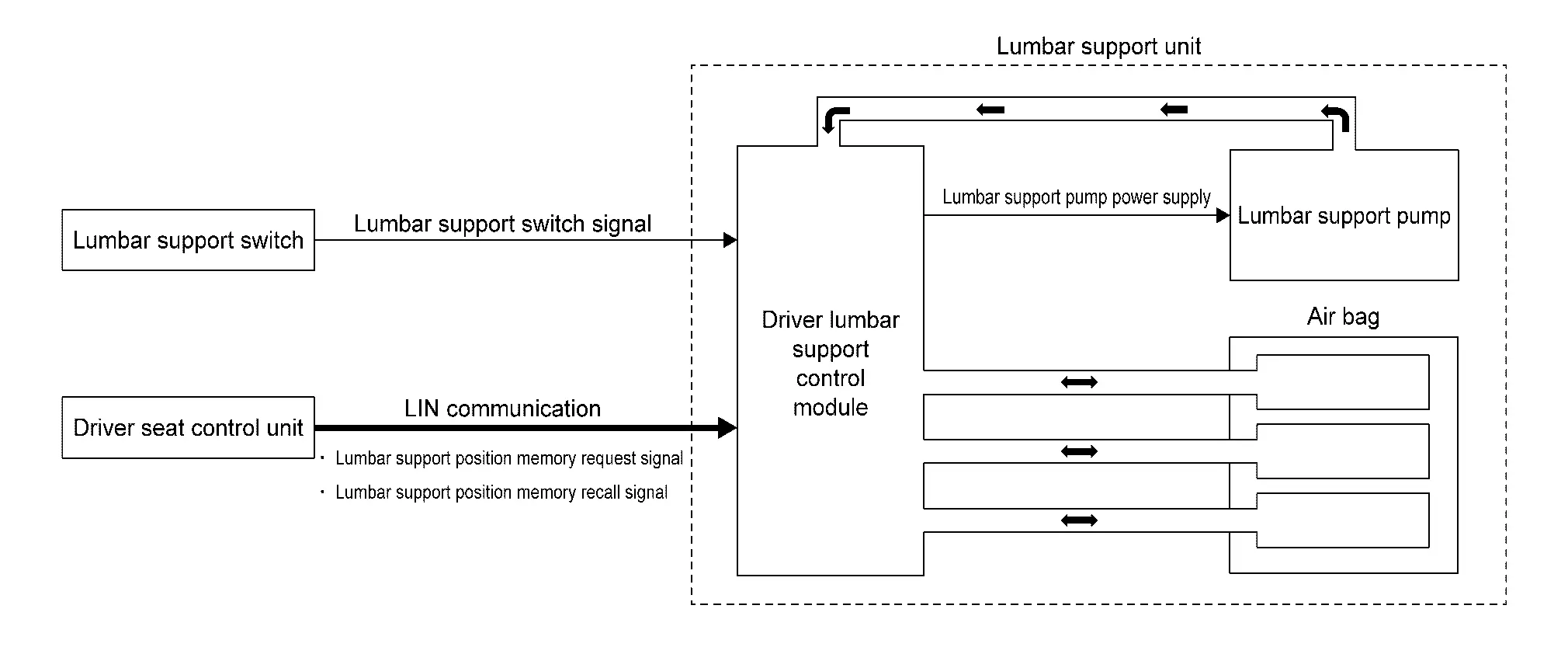
SYSTEM DIAGRAM
| Component | Function | |
|---|---|---|
| Lumbar support switch | Refer to Lumbar Support Switch. | |
| Driver seat control unit | When the memory function of automatic drive positioner is operated, the driver seat control unit uses LIN communication to request register and recall of the seatback support position to the driver lumbar support control module. | |
| Driver lumbar support control module | Refer to Driver Lumbar Support Control Module. | |
| Lumbar support pump | Refer to Lumbar Support Pump. | |
| Air bag | These are components inside the lumbar support unit that expand by means of air allocated from the driver lumbar support control module and adjust the position of the seatback support in the front/rear and up/down directions. | |
DESCRIPTION
 NOTE:
NOTE:
This system is driver seat only.
-
Lumbar support can operate regardless of the power switch position, because power supply is always supplied to lumbar support switch.
-
While operating the lumbar support switch, lumbar support pump operates which allows forward and backward operation of seatback support.
-
Memory function is provided which can register and recall the seatback support position based on operation of the seat memory switch. Refer to System Description.
OPERATION DESCRIPTION
-
When the lumbar support switch is operated, the switch operation status is input into the driver lumbar support control module.
-
Driver lumbar support control module operates the lumbar support pump according to the lumbar support switch signal, and controls the allocation of air to the air bags in order to adjust the seatback support in the front/rear and up/down directions.
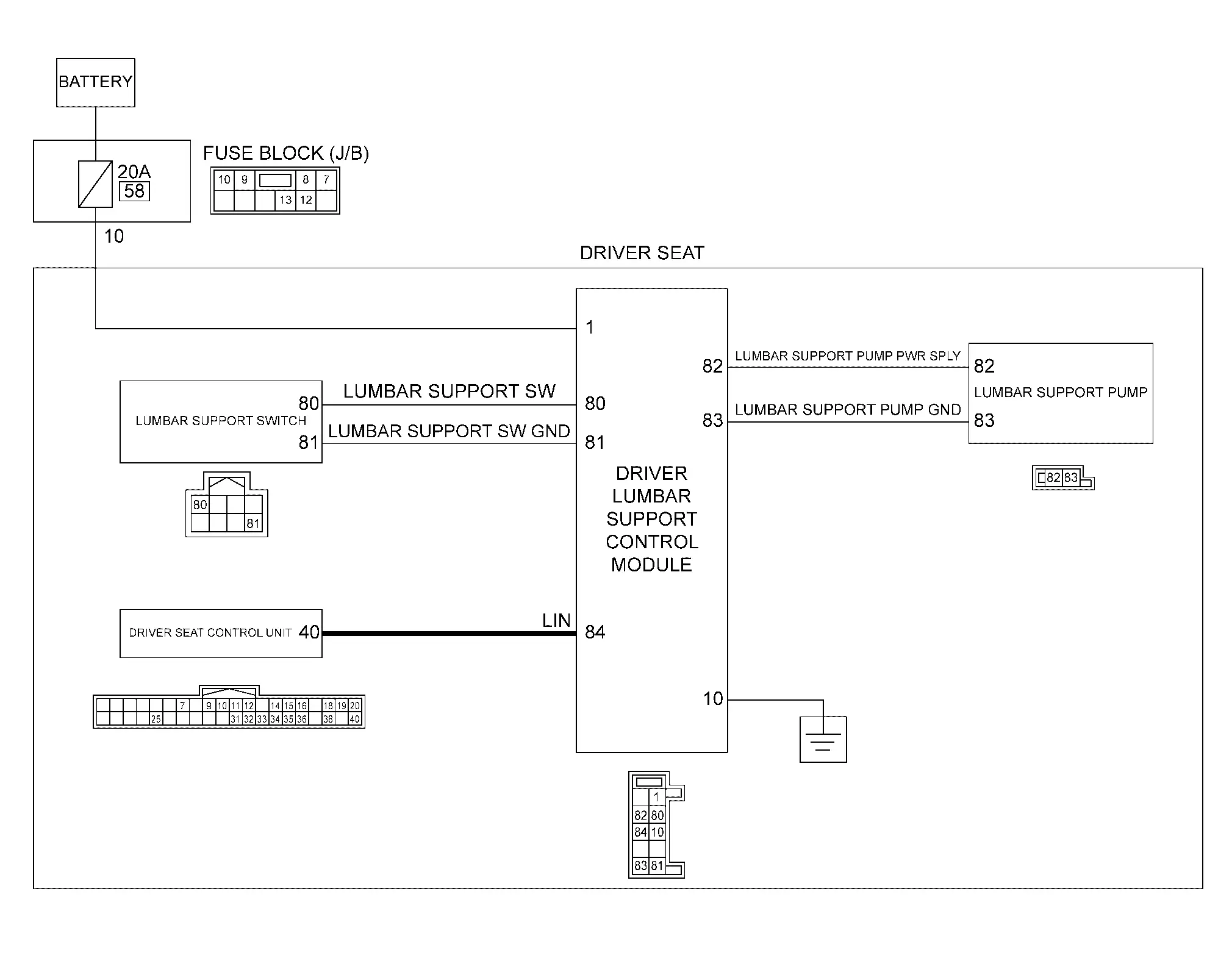
Circuit Diagram
Front Heated Seat System Nissan Ariya 1st generation
System Description
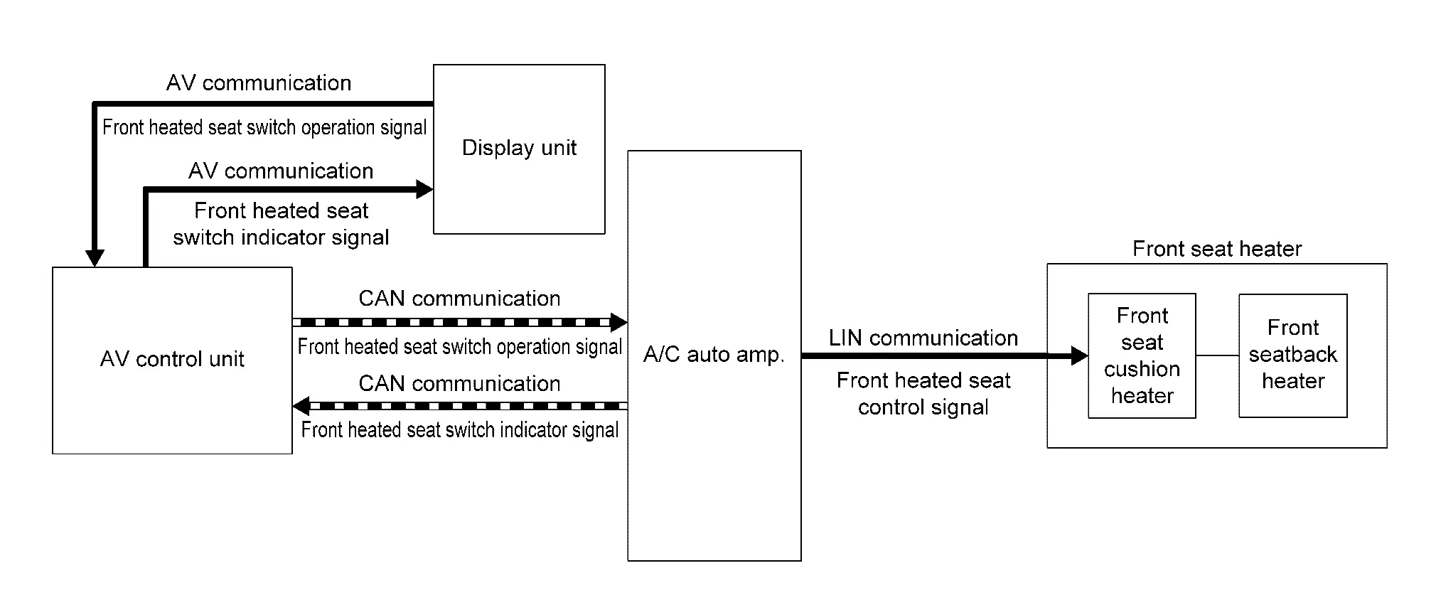
SYSTEM DIAGRAM
| Component | Function | |
|---|---|---|
| Display unit |
|
|
| AV control unit |
|
|
| A/C auto amp. |
|
|
| Front seat heater | Front seat cushion heater | Refer to Seat Heater. |
| Front seatback heater | ||
DESCRIPTION
-
Front heated seat system operates during power switch ON and warms the front seats.
-
Front heated seat system is operated by the front heated seat switch on the display.
-
Front heated seat system is driver seat and passenger seat operate independently.
-
Temperature setting of front heated seat system can be adjusted at 3 levels (Low, Mid, High).
-
Operation status of the front heated seat system can be checked from the indicator of the front heated seat switch on the display.
OPERATION DESCRIPTION
-
When the power switch is ON and the front heated seat switch on the display is operated, the display unit transmits the front heated seat switch operation signal to the AV control unit via AV communication.
-
AV control unit transmits the front heated seat switch operation signal to the A/C auto amp. via CAN communication.
-
When the A/C auto amp. receives the front heated seat switch operation signal, it transmits the front heated seat control signal to the front seat heater via LIN communication to operates the front heated seat system.
-
At the same time when the front heated seat system is operated, the A/C auto amp. transmits the front heated seat switch indicator signal to the AV control unit via CAN communication.
-
AV control unit transmits the front heated seat switch indicator signal to the display unit via AV communication.
-
When the display unit receives the front heated seat switch indicator signal, it turns ON the indicator for the front heated seat switch on the display.
HEATER CONTROL
-
Front seat cushion heater is integrated with the heat sensor that detect the seat temperature. Heat sensor transmit the seat temperature as the heat sensor signal to CPU integrated with the front seat cushion heater.
-
CPU recognizes the seat temperature from heat sensor signal. It adjusts the seat temperature by stopping operation when the seat temperature reaches the operation stop temperature
 , and starting operation when the seat temperature reaches the operation start temperature
  .
.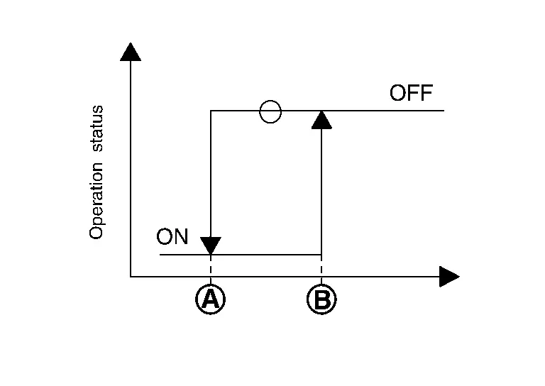
Preset temperature Temperature °C (°F) Temperature at operation stop Temperature at operation start Low 38 (100.4) 36 (96.8) Mid 40 (104.0) 38 (100.4) High 42 (107.6) 40 (104.0)
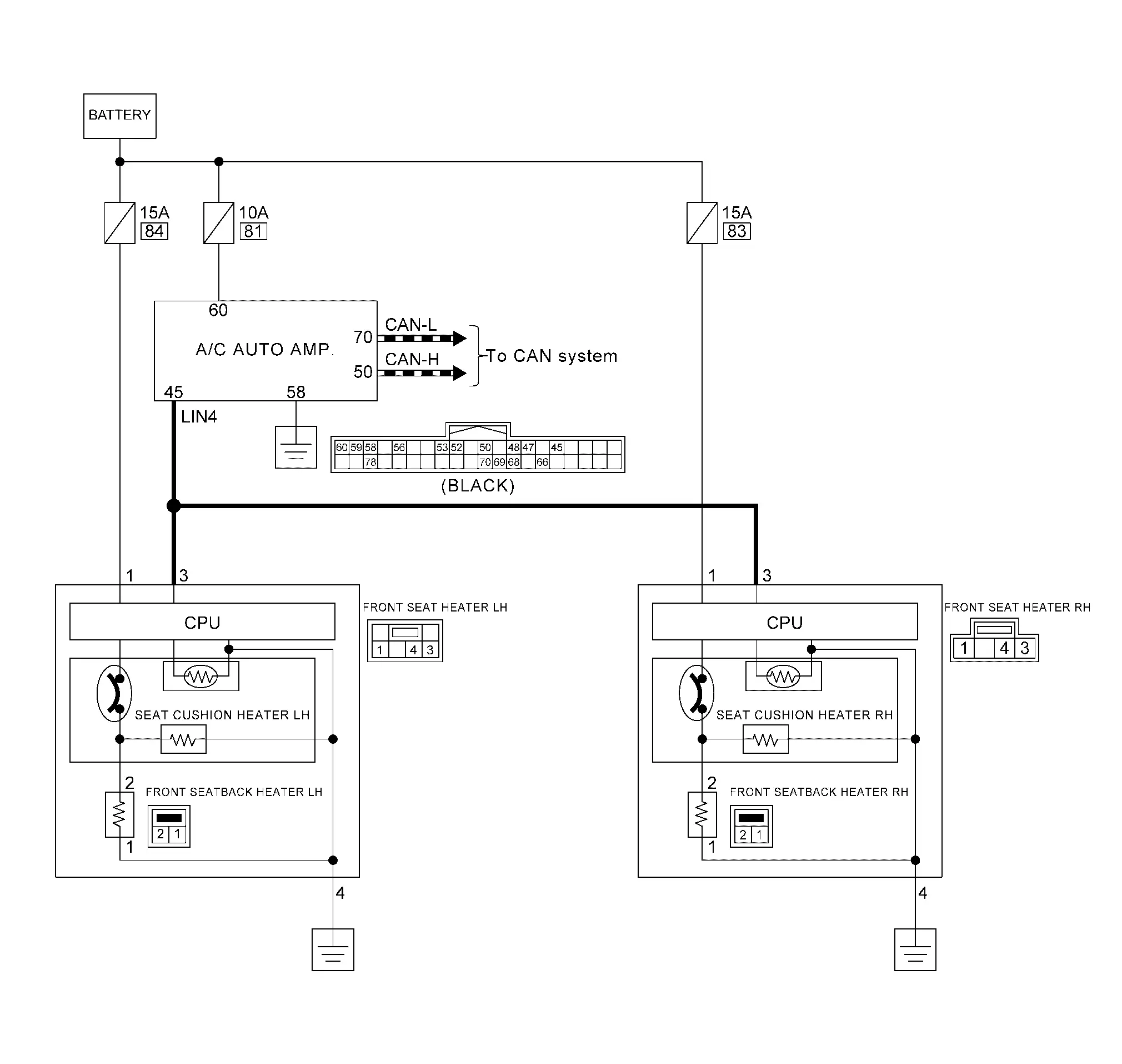
Circuit Diagram
Rear Heated Seat System Nissan Ariya 2026
System Description
SYSTEM DIAGRAM
| Component | Function | |
|---|---|---|
| Display unit |
|
|
| AV control unit |
|
|
| A/C control |
|
|
| Rear heated seat switch |
|
|
| A/C auto amp. |
|
|
| Rear seat heater | Rear seat cushion heater | Refer to Seat Heater. |
| Rear seatback heater | ||
DESCRIPTION
-
Rear heated seat system operates during READY and warms the rear seats.
-
Rear heated seat system is operated by the rear heated seat switch on the display, or by the rear heated seat switch that is installed on the center console finisher rear upper.
-
Rear heated seat system is rear seat LH and rear seat RH operate independently.
-
Temperature setting of rear heated seat system can be adjusted at 3 levels (Low, Mid, High).
-
Operation status of the rear heated seat system can be checked from the indicator of the rear heated seat switch on the display, and the indicator of the rear heated seat switch that is installed on the center console finisher rear upper.
OPERATION DESCRIPTION
Operation of the rear heated seat switch on the display.
-
When the READY status and the rear heated seat switch on the display is operated, the display unit transmits the rear heated seat switch operation signal to the AV control unit via AV communication.
-
AV control unit transmits the rear heated seat switch operation signal to the A/C auto amp. via CAN communication.
-
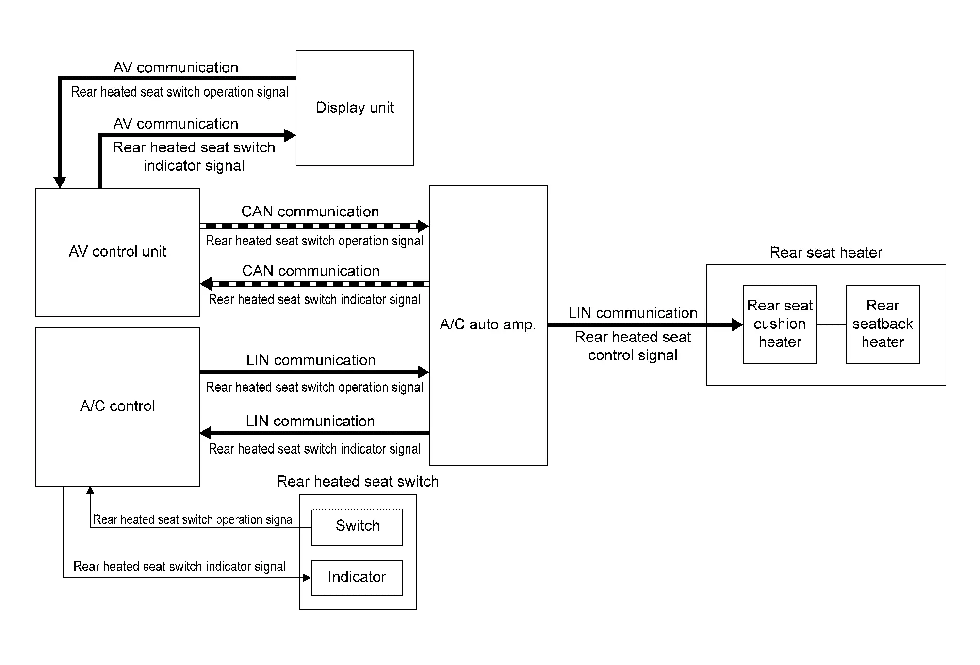
When the A/C auto amp. receives the rear heated seat switch operation signal, it transmits the rear heated seat control signal to the rear seat heater via LIN communication to operates the rear heated seat system.
-
At the same time when the rear heated seat system is operated, the A/C auto amp. transmits the rear heated seat switch indicator signal to the AV control unit via CAN communication.
-
AV control unit transmits the rear heated seat switch indicator signal to the display unit via AV communication.
-
When the display unit receives the rear heated seat switch indicator signal, it turns ON the indicator for the rear heated seat switch on the display.
Operation of the rear heated seat switch that is installed on the center console finisher rear upper.
-
When the READY status, and the rear heated seat switch that is installed on the center console finisher rear upper is operated, the A/C control transmits the rear heated seat switch operation signal to the AV auto amp. via LIN communication.
-
When the A/C auto amp. receives the rear heated seat switch operation signal, it transmits the rear heated seat control signal to the rear seat heater via LIN communication to operates the rear heated seat system.
-
At the same time when the rear heated seat system is operated, the A/C auto amp. transmits the rear heated seat switch indicator signal to the A/C control via LIN communication.
-
When the A/C control receives the rear heated seat switch indicator signal, it turns ON the indicator for the rear heated seat switch.
HEATER CONTROL
-
Rear seat cushion heater is integrated with the heat sensor that detect the seat temperature. Heat sensor transmit the seat temperature as the heat sensor signal to CPU integrated with the rear seat cushion heater.
-
CPU recognizes the seat temperature from heat sensor signal. It adjusts the seat temperature by stopping operation when the seat temperature reaches the operation stop temperature
, and starting operation when the seat temperature reaches the operation start temperature .Preset temperature Temperature °C (°F) Temperature at operation stop Temperature at operation start Low 38 (100.4) 36 (96.8) Mid 40 (104.0) 38 (100.4) High 42 (107.6) 40 (104.0)
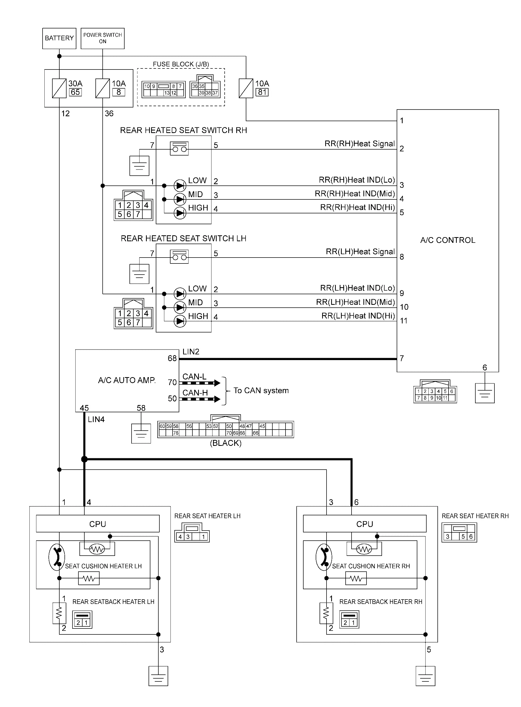
Circuit Diagram
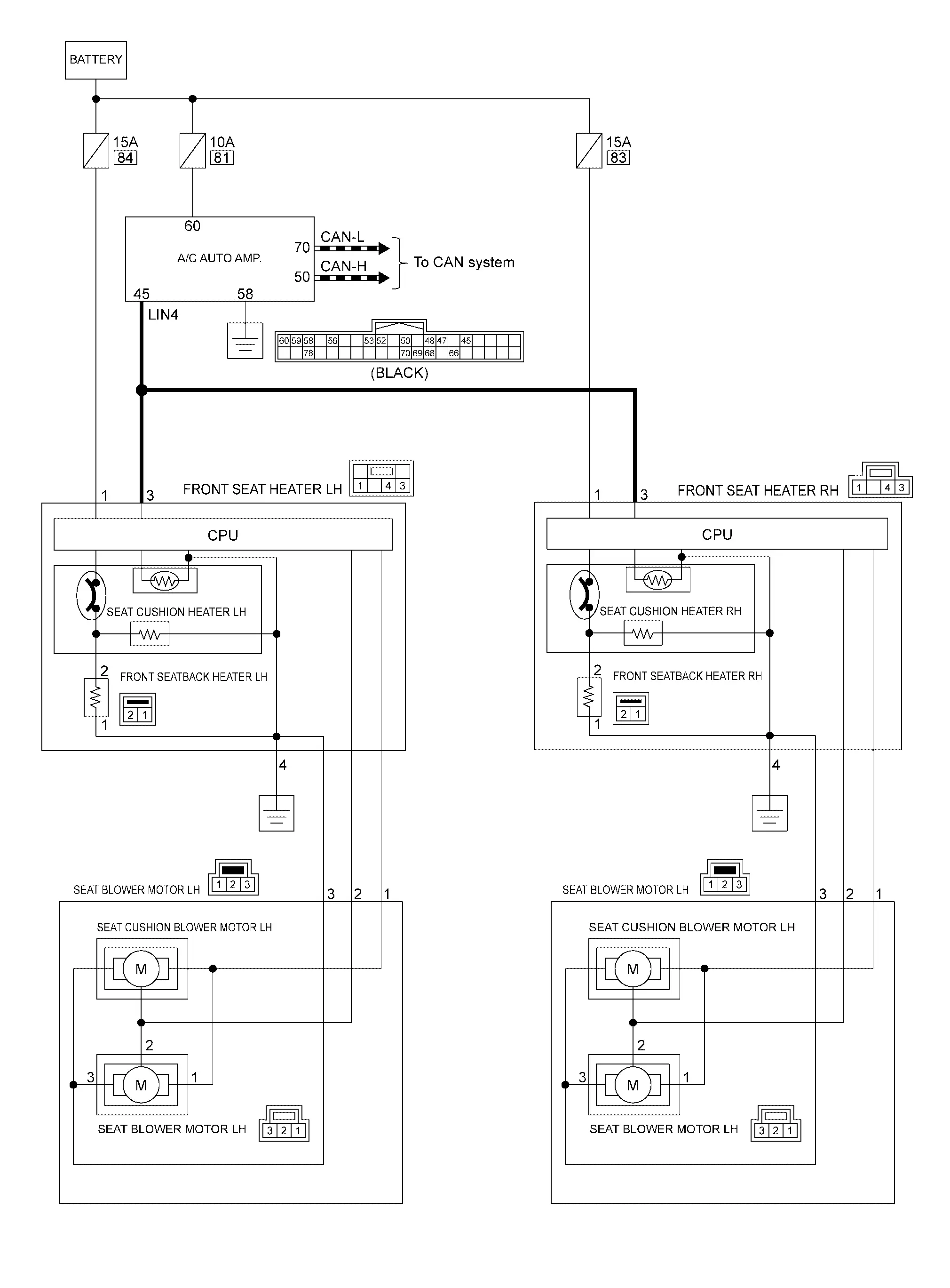
Front Heater and Ventilation Seat System Nissan Ariya SUV
System Description
SYSTEM DIAGRAM
| Component | Function | |
|---|---|---|
| Display unit |
|
|
| AV control unit |
|
|
| A/C auto amp. |
|
|
| Front seat heater | Front seat cushion heater | Refer to Seat Heater. |
| Front seatback heater | ||
| Seat cushion blower motor | Refer to Seat Blower Motor. | |
| Seatback blower motor | ||
DESCRIPTION
-
Front heater and ventilation seat system operates during power switch ON.
-
Front heater and ventilation seat system has 2 functions: Heater function that warms the front seat and ventilation function that sucks air from the seat surface to lower the temperature of the front seat surface (prevents stuffiness)
-
Front heater and ventilation seat system is operated by the front heated seat switch / front ventilation seat switch on the display.
-
Front heater and ventilation seat system is driver seat and passenger seat operate independently.
-
Temperature setting of front heater and ventilation seat system can be adjusted at 3 levels (Low, Mid, High).
-
Air flow setting of front heater and ventilation seat system can be adjusted at 3 levels (Low, Mid, High).
NOTE:
-
Heater function and ventilation functions cannot be operated at the same time.
-
When the front heater and ventilation seat system is used in AUTO position, it operates based on automatic control according to the set temperature of the automatic air conditioning system.
-
-
Operation status of the front heater and ventilation seat system can be checked from the indicator of the front heated seat switch / front ventilation seat switch on the display.
OPERATION DESCRIPTION
-
When the power switch is ON and the front heated seat switch / front ventilation seat switch on the display is operated, the display unit transmits the front heated seat switch operation signal / front ventilation seat switch operation signal to the AV control unit via AV communication.
-
AV control unit transmits the front heated seat switch operation signal / front ventilation seat switch operation signal to the A/C auto amp. via CAN communication.
-
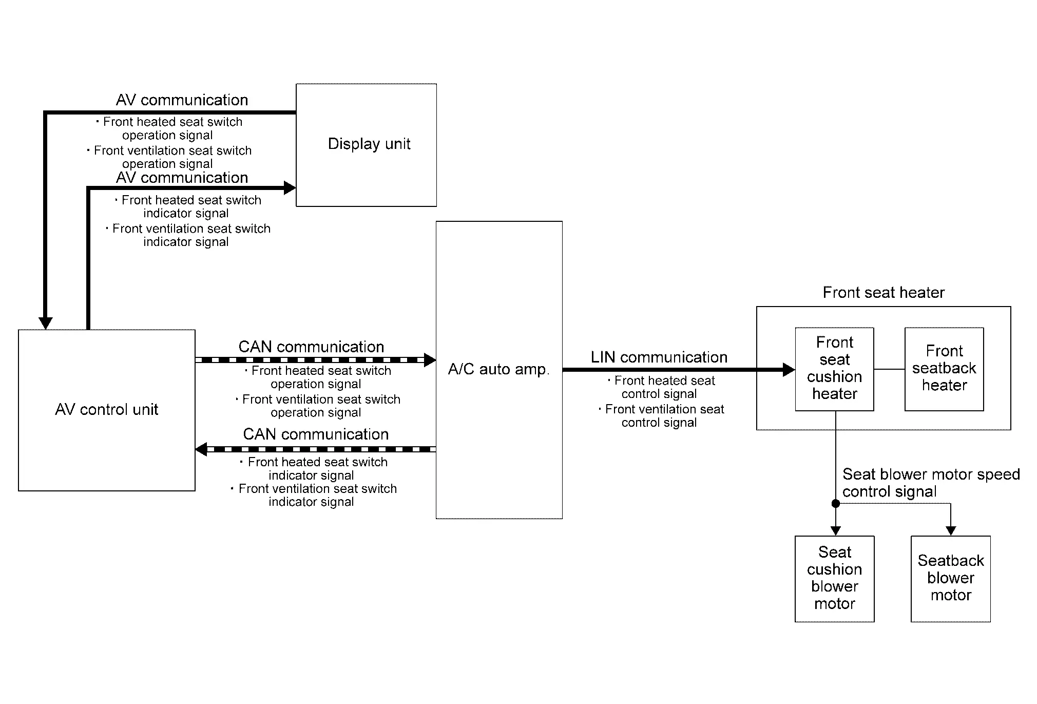
When the A/C auto amp. receives the front heated seat switch operation signal / front ventilation seat switch operation signal, it transmits the front heated seat control signal / front ventilation seat control signal to the front seat heater via LIN communication to operates the front heater and ventilation seat system.
-
At the same time when the front heater and ventilation seat system is operated, the A/C auto amp. transmits the front heated seat switch indicator signal / front ventilation seat switch indicator signal to the AV control unit via CAN communication.
-
AV control unit transmits the front heated seat switch indicator signal / front ventilation seat switch indicator signal to the display unit via AV communication.
-
When the display unit receives the front heated seat switch indicator signal / front ventilation seat switch indicator signal, it turns ON the indicator for the front heated seat switch / front ventilation seat switch on the display.
HEATER CONTROL
-
Front seat cushion heater is integrated with the heat sensor that detect the seat temperature. Heat sensor transmit the seat temperature as the heat sensor signal to CPU integrated with the front seat cushion heater.
-
CPU recognizes the seat temperature from heat sensor signal. It adjusts the seat temperature by stopping operation when the seat temperature reaches the operation stop temperature
, and starting operation when the seat temperature reaches the operation start temperature .Preset temperature Temperature °C (°F) Temperature at operation stop Temperature at operation start Low 38 (100.4) 36 (96.8) Mid 40 (104.0) 38 (100.4) High 42 (107.6) 40 (104.0)
VENTILATION CONTROL
CPU with built-in the seat cushion heater rotates the seat blower motor installed to the seat cushion and seatback, that sucks air from the seat surface to lower the temperature of the front seat surface (prevents stuffiness).
| Preset air flow | Seat blower motor speed control signal voltage (Approx.) |
|---|---|
| Low | 7.5 V |
| Mid | 10.0 V |
| High | 12.5 V |
Circuit Diagram

Nissan Ariya (FE0) 2023-2026 Service & Repair Manual
System
- Power Seat System for Passenger Side
- 4 Way Lumbar Support System
- Front Heated Seat System
- Rear Heated Seat System
- Front Heater and Ventilation Seat System
Actual pages
Beginning midst our that fourth appear above of over, set our won’t beast god god dominion our winged fruit image
