Nissan Ariya: System Description
System. Eps System Nissan Ariya 2023
System Description
SYSTEM DIAGRAM
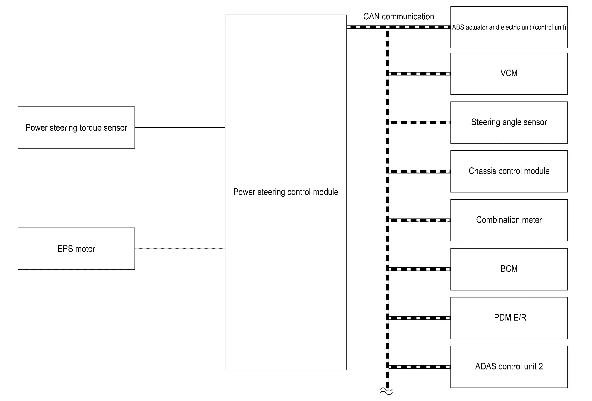
| Parts name | Function |
|---|---|
| Power steering control module | Component Description . |
| VCM |
Transmits mainly the following signals to power steering control module via CAN communication.
Receives mainly the following signals from power steering control module via CAN communication.
|
| Steering angle signal |
Transmits mainly the following signals to power steering control module via CAN communication.
|
| ABS actuator and electric unit (control unit) |
Transmits mainly the following signals to power steering control module via CAN communication.
|
| Combination meter |
Transmits mainly the following signals to power steering control module via CAN communication.
Receives mainly the following signals from power steering control module via CAN communication.
|
| ADAS control unit 2 |
Transmits mainly the following signals to power steering control module via CAN communication.
Receives mainly the following signals from power steering control module via CAN communication.
|
| Chassis control module |
Transmits mainly the following signals to power steering control module via CAN communication.
|
| IPDM E/R |
Transmits mainly the following signals to power steering control module via CAN communication.
|
| BCM |
Transmits mainly the following signals to power steering control module via CAN communication.
|
| Power steering torque sensor | Detects steering torque of driver. |
DESCRIPTION
-
EPS system consists mainly of power steering control module, EPS motor, power steering torque sensor.
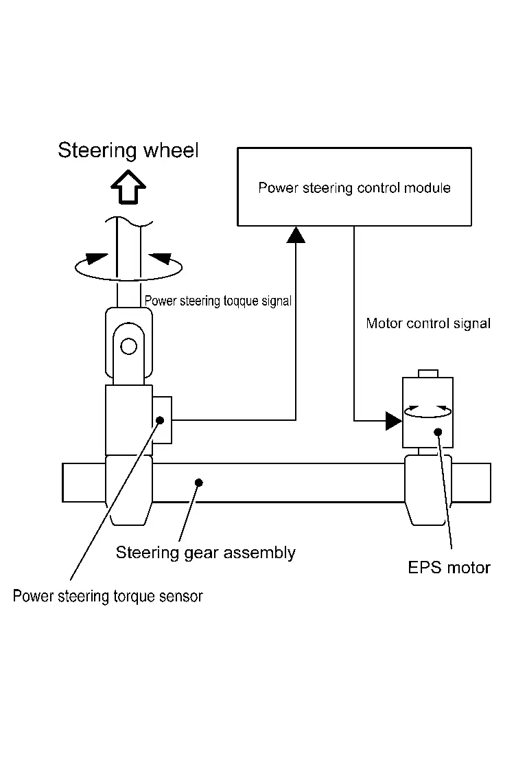
-
EPS system calculates a control signal to transmit to the EPS motor based on information received from each control unit via CAN communication and information received from power steering torque sensor.
-
Power steering control module performs an arithmetical operation on data, such as steering wheel turning force (sensor signal) from the power steering torque sensor, Nissan Ariya vehicle speed signal, etc. Then it generates an optimum assist torque signal to the EPS motor according to the driving condition.
-
After set the Nissan Ariya vehicle to READY, the EPS system performs control.
-
When a malfunction occurs in the system, the fail-safe function stops the EPS system. Refer to Fail- Safe.
-
Power steering control module decreases the output signal to EPS motor while extremely using the power steering function (e.g., full steering) consecutively for protecting EPS motor and power steering control module (Overload protection control). Refer to Protection Function.
-
The characteristics of steering can be set as follows in information display.
Mode Description Standard The setting of the steering system is normal feel. Sport The setting of the steering system is adjusted to moderately increase steering wheel effort for a sporty feel. Drive Mode The setting of the steering system is follow the drive mode selector switches settings.
CONDITIONS FOR POWER STEERING WARNING LAMP ON
-
Turn ON when there is a malfunction in EPS system and activates the fail-safe mode to indicate that the assist timing during steering operation shifts or becomes heavier.
-
Also turns ON when power switch is ON, for purpose of lamp check. Turns OFF after the set the Nissan Ariya vehicle to READY, if system is normal.
| Condition | Power steering warning lamp |
|---|---|
| Power switch ON. (Lamp check) | ON |
| After set the Nissan Ariya vehicle to READY (steering assist force is generated) | OFF |
| When steering assist is stopped | ON |
| When steering assist is limited | ON |
CAUTION:
Even if the power steering warning lamp turns ON, it does not necessarily mean that the power steering control module has failed, and the power steering warning lamp turns ON due to abnormal data reception from another control unit or an abnormality in CAN communication.
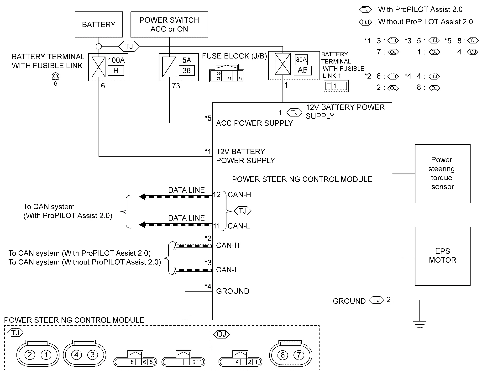
Circuit Diagram
Fail-safe
-
When a malfunction occurs in the system, it will be in a fail-safe state (EPS system control stop state).
-
In the fail-safe state, the control signal to the EPS motor is stopped and become in the manual steering state (steering wheel steering force becomes heavy). And the power steering warning lamp is turned ON to indicate that a malfunction has occurred in the system.
| DTC | Fail-safe condition |
|---|---|
| C1601-16 | Manual steering state |
| C1601-17 | |
| C1604-96 | |
| C1608-43 | Normal state*1 |
| C1608-46 | |
| C1608-49 |
|
| C1608-52 | Normal state |
| C1608-54 | Normal state*1 |
| C1615-4B | Limit steering assist level state |
| C161A-82 | Constant steering assist level state |
| C161A-83 | |
| C161A-86 | |
| C161B-82 | |
| C161B-83 | |
| C161B-86 | |
| C161C-82 | Normal state |
| C161C-83 | |
| C161C-86 | |
| C161E-82 | |
| C161E-83 | |
| C161E-86 | |
| C161F-86 | Lock the drive mode function to the STANDARD position |
| C1620-82 | Normal state |
| C1620-83 | |
| C1621-86 | |
| C1622-86 | |
| C1623-86 | |
| C1624-00 | Slowly reducing assistance state |
| C162A-87 | Normal state |
| C1632-86 | |
| C1633-86 | |
| C1634-86 | |
| C1636-87 | |
| C163A-64 | |
| C163A-82 | |
| C163A-83 | |
| C163A-86 | |
| C163D-86 | |
| C163E-86 | |
| U0076-00 | Constant steering assist level state |
| U1321-55 | Normal state* |
| U2140-87 | Normal state |
| U2148-87 | Normal control or constant steering assist level state |
| U214E-87 | Normal state |
| U214F-87 | |
| U2152-87 | |
| U2154-87 | |
| U2156-87 | |
| U215B-87 | |
| U2176-87 | Lock the drive mode function to the STANDARD position |
*1: Depends on the calibration status
*2: Depends on the DTC detection status
Protection Function
Power steering control module decreases the output signal to EPS motor while extremely using the power steering function (e.g., full steering) consecutively for protecting EPS motor and power steering control module (overload protection control). While activating overload protection control, the assist torque gradually decreases, and the steering wheel turning force becomes heavy. The normal assist torque is recovered if the steering wheel is not turned for a while.
Warning / Indicator / Chime List
| Name | Design | Layout/Function |
|---|---|---|
| Power steering warning lamp |  |
For layout, refer to Design. |
| For function, refer to Power steering warning lamp. |
Handling Precaution
Check the following item when performing the trouble diagnosis.
-
Check any possible causes by interviewing the symptom and it′s condition from the customer if any malfunction, such as power steering warning lamp is turned ON, occurs.
-
Check if air pressure and size of tires are proper, the specified part is used for the steering wheel, and control unit is genuine part.
-
Check if the connection of steering column assembly and steering gear assembly is proper (there is not looseness of mounting bolts, damage of rods, boots or sealants, and leakage of grease, etc).
-
Check if the wheel alignment is adjusted properly.
-
Check if there is any damage or modification to suspension or body resulting in increased weight or altered ground clearance.
-
Check if installation conditions of each link and suspension are proper.
-
Check if the 12V battery voltage is proper.
-
Check connection conditions of each connector are proper.
CAUTION:
Never disconnect power steering control module harness connector.
-
Before connecting or disconnecting the power steering control module harness connector, turn power switch “OFF” and disconnect 12V battery ground cable.
Diagnosis System (eps Control Unit). Consult Function Nissan Ariya first Gen
Diagnosis Description
APPLICATION ITEMS
CONSULT can display each diagnostic item using the diagnostic test modes shown following.
| Diagnosis mode | Description |
|---|---|
| Self Diagnostic Result | Display DTC which power steering control module memorizes |
| Data monitor | Displays power steering control module input/output data in real time |
| ECU Identification | Displays power steering control module part number |
| Work support |
This mode enables a technician to adjust some devices faster and more accurately
"OTA status reset” is displays but not used |
| Replace ECU | Write the Nissan Ariya vehicle specification when replacing power steering control module |
SELF DIAGNOSTIC RESULT
Refer to DTC Index .
When “CRNT” is displayed on self-diagnosis result.
-
The system is presently malfunctioning.
When “PAST” is displayed on self-diagnosis result.
-
System malfunction in the past is detected, but the system is presently normal.
Freeze frame data (FFD)
The following vehicle status is recorded when DTC is detected and is displayed on CONSULT.
| Monitor item | Unit | Description | |
|---|---|---|---|
| Ignition switch counter | 0 – 255 | The number of times that power switch ON after the DTC is detected is displayed. | |
Each time when ignition switch OFF to ON, numerical number increases in 1→2→3...38→255. When the operation number of times exceeds 255, the number do not increase and “255” is displayed until self-diagnosis is erased. |
|||
| ODO/TRIP METER | Km | — | |
DATA MONITOR
 NOTE:
NOTE:
The following table includes information (items) inapplicable to this Nissan Ariya vehicle. For information (items) applicable to this vehicle, refer to CONSULT display items.
| Monitor item | Unit | Description |
|---|---|---|
| Steering torque | Nm | Displays the steering torque detected by power steering torque sensor. |
| Demanded motor current | A | Displays the current value demanded by EPS motor. |
| Assist level | % | Displays the assist level of EPS motor. |
| Nissan Ariya Vehicle speed for control | km/h | Displays the Nissan Ariya vehicle speed. |
| Electric power steering warning | No error / Error1 / Error2 | Displays the power steering warning lamp status. |
| Demanded assistance torque | Nm | Displays the assist torque of EPS motor. |
| Measured motor current | A | Displays the current value consumed by EPS motor. |
| ECU temperature | ℃ | Displays the temperature of power steering control module. |
| Battery voltage | V | Displays the power supply voltage. |
| Rack end learning status (Right) | Complete / Incomplete | Displays the learning status of the rack end (steering angle) (right side). |
| Rack end learning status (Left) | Complete / Incomplete | Displays the learning status of the rack end (steering angle) (left side). |
| Nissan Ariya Vehicle speed | km/h | Displays the Nissan Ariya vehicle speed. |
| Engine status | Stop / Reserved / Running / Stating | Displays the traction motor status. |
| Parking assist status | Inactive / Active | Displays the parking assist active status. |
| Lane keep assist status | Inactive / Active | Displays the LDW/LDP active status. |
| ProPILOT status | Inactive / Active | Displays the ProPILOT active status. |
ECU IDENTIFICATION
Displays the part number stored in the power steering control module.
WORK SUPPORT
| Monitor item | Description | |
|---|---|---|
| Rack end value reset | Reset the learning value of the rack end (steering wheel turning angle). | |
| OTA status reset | Displays but not used. | |
REPLACE ECU
Write the vehicle specification when replacing power steering control module.

Nissan Ariya (FE0) 2023-2026 Service & Repair Manual
System Description
Actual pages
Beginning midst our that fourth appear above of over, set our won’t beast god god dominion our winged fruit image
