Nissan Ariya: System
- Intelligent Key System/ready Set Function. 2wd Models
- Nissan Vehicle Immobilizer System. 2wd Models
- Vehicle Security System
Intelligent Key System/ready Set Function. 2wd Models Nissan Ariya: FE0
System Description
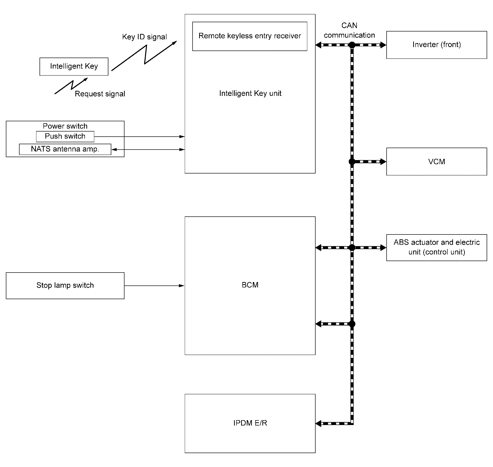
SYSTEM DIAGRAM
| Component | Function | |
|---|---|---|
| Stop lamp switch | Stop lamp switch detects that brake pedal is depressed, and then transmits stop lamp switch signal to BCM. | |
| ABS actuator and electric unit (control unit) | ABS actuator and electric unit (control unit) transmits the Nissan Ariya vehicle speed signal to BCM via CAN communication. | |
| VCM | VCM detects that selector lever is locked in the P position, then transmits shift position signal to BCM via CAN communication. | |
| IPDM E/R | IPDM E/R detected power switch status and the transmits power switch ON signal to BCM via CAN communication. | |
| BCM | BCM receives stop lamp switch signal from the stop lamp switch. | |
| Power switch | Push switch |
|
| NATS antenna amp. | Refer to NATS Antenna Amp.. | |
| Intelligent Key | Intelligent Key transmits the key ID to Intelligent Key unit. | |
| Intelligent Key unit |
|
|
| Inverter (front) | When power switch is turned ON, Intelligent Key unit starts communication with inverter (front) and performs the ID verification between Intelligent Key unit and inverter (front). If the verification result is OK, the Nissan Ariya vehicle can be set to READY. If the verification result is NG, the vehicle cannot be set to READY. | |
BCM INPUT/OUTPUT SIGNAL CHART
Input Signal Item
| Transmit unit | Signal name | |
|---|---|---|
| IPDM E/R | CAN communication | Power switch ON signal |
| ABS actuator and electric unit (control unit) | Nissan Ariya Vehicle speed signal | |
| VCM | Shift position signal | |
| Stop lamp switch | Stop lamp switch signal | |
Output Signal Item
| Reception unit | Signal name | |
|---|---|---|
| IPDM E/R | CAN communication | Power switch ON signal |
| VCM | READY signal | |
INTELLIGENT KEY UNIT INPUT/OUTPUT SIGNAL CHART
Input Signal Item
| Transmit unit | Signal name | |
|---|---|---|
| VCM | CAN communication | READY condition signal |
| NATS antenna amp. | Key ID signal | |
| Push switch | Power switch signal | |
Output Signal Item
| Reception unit | Signal name | |
|---|---|---|
| BCM | CAN communication | Power switch signal |
SYSTEM DESCRIPTION
-
The READY set function of Intelligent Key system makes it possible to set the vehicle to READY without using the Intelligent Key, based on the electronic ID verification. The electronic ID verification is performed between Intelligent Key unit and Intelligent Key when the power switch is pressed while the Intelligent Key is within the detection area of NATS antenna amp.
 NOTE:
NOTE:
The driver should carry the Intelligent Key at all times.
-
Intelligent Key has 2 IDs (Intelligent Key ID and NATS ID). It can perform the door lock/unlock operation and the power switch operation when the registered Intelligent Key is carried.
-
If the ID is successfully verified, power switch operation can be available, and the Nissan Ariya vehicle can be set to READY.
-
Up to 4 Intelligent Keys can be registered upon request from the customer.
NOTE:
For any functions other than the READY set function of Intelligent Key system. Refer to System Description.
PRECAUTIONS FOR INTELLIGENT KEY SYSTEM
The transponder (the chip for NATS ID verification) is integrated into the Intelligent Key. Therefore, ID verification cannot be performed by mechanical key only.
In that case, NATS ID verification can be performed when Intelligent Key backside is contacted to power switch while push switch is pressed. If verification result is OK, the Nissan Ariya vehicle can be set to READY.
OPERATION WHEN INTELLIGENT KEY IS CARRIED
-
When the power switch is pressed, Intelligent Key unit activates the NATS antenna amp. and transmits the request signal to the Intelligent Key.
-
The Intelligent Key receives the request signal and transmits the Intelligent Key ID signal to Intelligent Key unit.
-
Intelligent Key unit receives the Intelligent Key ID signal, and verifies it with the registered ID.
-
BCM transmits power switch ON signal to IPDM E/R.
-
When power switch is turned ON, Intelligent Key unit starts communication with inverter (front) and performs the ID verification between Intelligent Key unit and inverter (front). If the verification result is OK, the Nissan Ariya vehicle can be set to READY.
-
BCM detects that the brake pedal operating condition.
-
VCM detects that the shift position.
-
BCM transmits READY signal to VCM if BCM judges that the READY set condition* is satisfied.
*: For READY set condition, refer to “READY SET CONDITION TABLE BY POWER SWITCH OPERATION” below.
CAUTION:
-
If a malfunction is detected in the Intelligent Key system, Intelligent Key system malfunction on information display appears. In this case, BCM does not transmits READY signal.
-
When the Intelligent Key is carried outside of the Nissan Ariya vehicle (NATS antenna amp. detection area) while the power switch position is ON, BCM does not transmits READY signal even if READY set condition* is satisfied.
-
OPERATION RANGE
Vehicle can be set to READY when Intelligent Key is inside the vehicle. However, sometimes vehicle may not be set to READY when Intelligent Key is on instrument panel or in glove box.
READY SET CONDITION TABLE BY POWER SWITCH OPERATION
The vehicle can be set to READY by the following operations.
NOTE:
-
When an Intelligent Key is within the detection area of NATS antenna amp. and when Intelligent Key backside is contacted to power switch, it is equivalent to the operations below.
-
When setting the Nissan Ariya vehicle to READY, the Intelligent Key unit monitors READY set conditions,
-
Brake pedal operating condition
-
Shift position
-
Nissan Ariya Vehicle speed
-
Vehicle speed: less than 4 km/h (2.5 MPH)
| Power supply position | Condition | Power switch operation frequency | |
|---|---|---|---|
| Shift position | Brake pedal operation condition | ||
| OFF → ON | — | Not depressed | 1 |
| OFF → ON → OFF | — | Not depressed | 2 |
|
OFF → ON (READY) ON (Not READY) → ON (READY) |
P or N position | Depressed | 1 |
| ON (READY) → OFF | — | — | 1 |
NOTE:
If the Intelligent Key unit cannot detect that the Intelligent Key is in the Nissan Ariya vehicle, power switch cannot be turned OFF.
However, power switch can be turned off by performing of the following operation.
-
Press and hold the power switch for 2 seconds or more.
-
Press the power switch 3 times or more within 1.5 seconds.
Vehicle speed: 4 km/h (2.5 MPH) or more
| Power supply position | Condition | Power switch operation frequency | |
|---|---|---|---|
| Shift position | Brake pedal operation condition | ||
| ON (READY) → OFF | — | — | Emergency stop operation |
|
OFF → ON (READY) (Return operation after emergency stop operation while driving) |
N position | Not depressed | 1 |
Emergency stop operation
-
Press and hold the power switch for 2 seconds or more.
-
Press the power switch 3 times or more within 1.5 seconds.
Nissan Vehicle Immobilizer System. 2wd Models Nissan Ariya: FE0
System Description
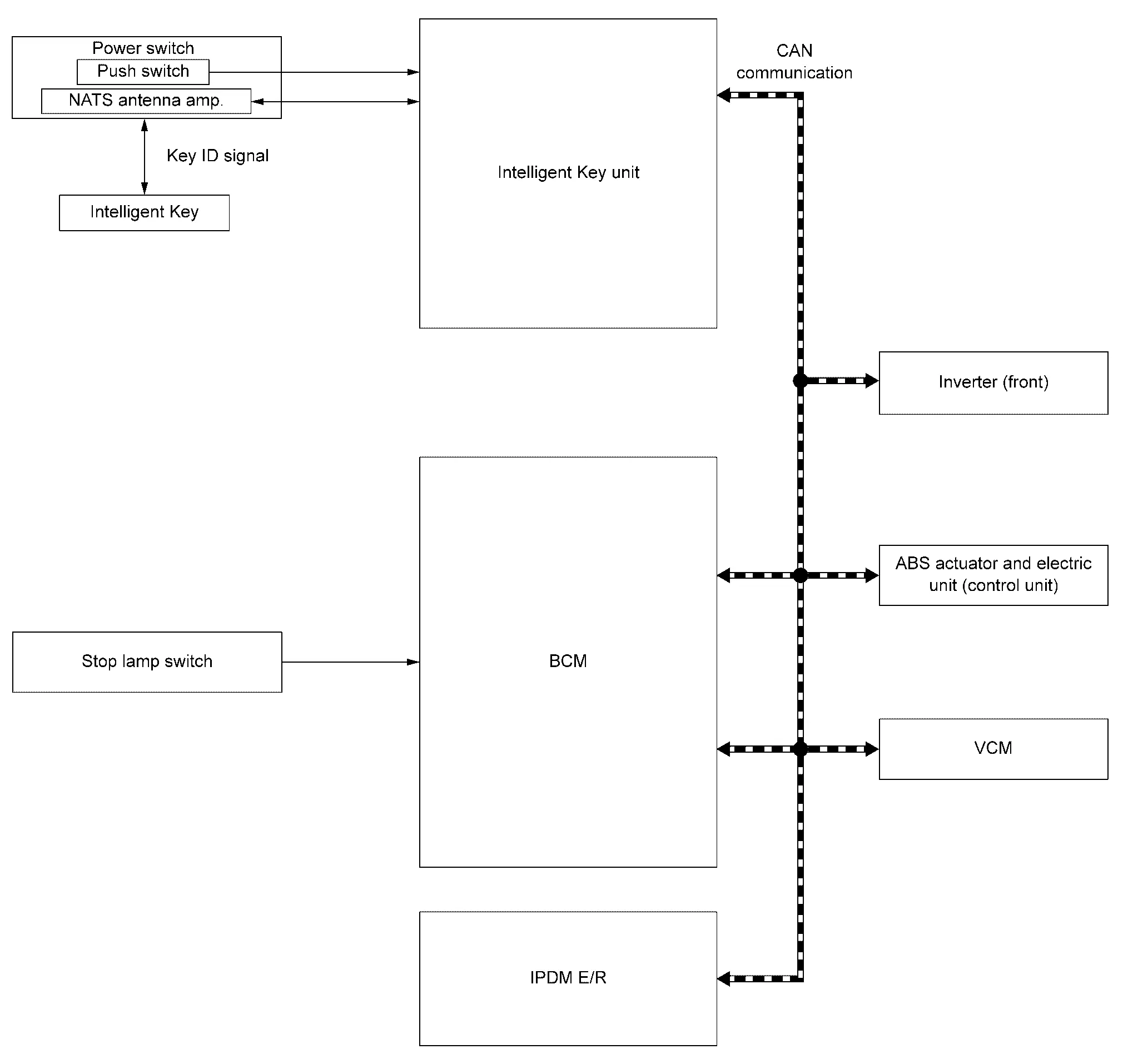
SYSTEM DIAGRAM
| Component | Function | |
|---|---|---|
| Stop lamp switch | Stop lamp switch detects that brake pedal is depressed, and then transmits stop lamp switch signal to BCM. | |
| ABS actuator and electric unit (control unit) | ABS actuator and electric unit (control unit) transmits the Nissan Ariya vehicle speed signal to BCM via CAN communication. | |
| VCM | VCM detects that selector lever is locked in the P position, then transmits shift position signal to BCM via CAN communication. | |
| Inverter (front) | When power switch is turned ON, Intelligent Key unit starts communication with inverter (front) and performs the ID verification between Intelligent Key unit and inverter (front). If the verification result is OK, the Nissan Ariya vehicle can be set to READY. If the verification result is NG, the vehicle cannot be set to READY. | |
| IPDM E/R | IPDM E/R detected power switch status and the transmits power switch ON signal to BCM via CAN communication. | |
| BCM | BCM receives stop lamp switch signal from the stop lamp switch. | |
| Power switch | Push switch |
|
| NATS antenna amp. | Refer to NATS Antenna Amp.. | |
| Intelligent Key | Intelligent Key (trans ponder built in) transmits the key ID to Intelligent Key unit. | |
| Intelligent Key unit |
|
|
BCM INPUT/OUTPUT SIGNAL CHART
Input Signal Item
| Transmit unit | Signal name | |
|---|---|---|
| IPDM E/R | CAN communication | Power switch ON signal |
| ABS actuator and electric unit (control unit) | Nissan Ariya Vehicle speed signal | |
| VCM | Shift position signal | |
| Stop lamp switch | Stop lamp switch signal | |
Output Signal Item
| Reception unit | Signal name | |
|---|---|---|
| IPDM E/R | CAN communication | Power switch ON signal |
| VCM | READY signal | |
INTELLIGENT KEY UNIT INPUT/OUTPUT SIGNAL CHART
Input Signal Item
| Transmit unit | Signal name | |
|---|---|---|
| VCM | CAN communication | READY condition signal |
| NATS antenna amp. |
|
|
| Push switch | Power switch signal | |
Output Signal Item
| Reception unit | Signal name | |
|---|---|---|
| BCM | CAN communication | Power switch signal |
| NATS antenna amp. | Key ID request signal | |
SYSTEM DESCRIPTION
-
The NISSAN VEHICLE IMMOBILIZER SYSTEM (NVIS) prevents the vehicle from being set to READY by Intelligent Key whose ID is not registered to the Nissan Ariya vehicle (Intelligent Key unit). It has higher protection against auto theft involving the duplication of mechanical keys.
-
The mechanical key integrated in the Intelligent Key cannot set the Nissan Ariya vehicle to READY. When the Intelligent Key battery is discharged, the NATS ID verification is performed between the transponder integrated with Intelligent Key and Intelligent Key unit via NATS antenna amp. when the Intelligent Key backside is connected to power switch after power switch pressed. If the verification result is OK, the Nissan Ariya vehicle can be set to READY by the power switch operation.
-
Up to 4 Intelligent Keys can be registered upon request from the customer.
-
When replacing VCM, Intelligent Key unit, BCM, inverter (front) or Intelligent Key, the specified procedure (Initialization and registration) using CONSULT is required.
PRECAUTIONS FOR KEY REGISTRATION
The ID registration is a procedure that erases the current NATS ID once, and then registers a new ID. Therefore before starting the registration operation, collect all registered Intelligent Keys from the customer.
OPERATION WHEN INTELLIGENT KEY IS CONTACTED TO POWER SWITCH
-
When power switch is pressed while shift position is in the P position, Intelligent Key unit activates NATS antenna amp. is integrated in power switch.
-
When Intelligent Key (transponder built-in) backside is contacted to power switch, Intelligent Key unit starts NATS ID verification between Intelligent Key unit and Intelligent Key (transponder built-in) via NATS antenna amp.
-
BCM transmits power switch ON signal to IPDM E/R.
-
When the power switch is turned to ON, Intelligent Key unit performs ID verification with the inverter (front). When the result is OK, Nissan Ariya vehicle can be set to READY.
-
BCM detects that the brake pedal operating condition.
-
VCM detects that the shift position.
-
BCM transmits READY signal to VCM if BCM judges that the READY set condition* is satisfied.
*:For the READY set conditions, refer to “READY SET CONDITION TABLE BY POWER SWITCH OPERATION” below.
READY SET CONDITION TABLE BY POWER SWITCH OPERATION
The vehicle can be set to READY by the following operations.
NOTE:
-
When an Intelligent Key is within the detection area of NATS antenna amp. and when Intelligent Key backside is contacted to power switch, it is equivalent to the operations below.
-
When setting the Nissan Ariya vehicle to READY, the Intelligent Key unit monitors READY set conditions,
-
Brake pedal operating condition
-
Shift position
-
Nissan Ariya Vehicle speed
-
Vehicle speed: less than 4 km/h (2.5 MPH)
| Power supply position | Condition | Power switch operation frequency | |
|---|---|---|---|
| Shift position | Brake pedal operation condition | ||
| OFF → ON | — | Not depressed | 1 |
| OFF → ON → OFF | — | Not depressed | 2 |
|
OFF → ON (READY) ON (Not READY) → ON (READY) |
P or N position | Depressed | 1 |
| ON (READY) → OFF | — | — | 1 |
NOTE:
If the Intelligent Key unit cannot detect that the Intelligent Key is in the Nissan Ariya vehicle, power switch cannot be turned OFF.
However, power switch can be turned off by performing of the following operation.
-
Press and hold the power switch for 2 seconds or more.
-
Press the power switch 3 times or more within 1.5 seconds.
Vehicle speed: 4 km/h (2.5 MPH) or more
| Power supply position | Condition | Power switch operation frequency | |
|---|---|---|---|
| Shift position | Brake pedal operation condition | ||
| ON (READY) → OFF | — | — | Emergency stop operation |
|
OFF → ON (READY) (Return operation after emergency stop operation while driving) |
N position | Not depressed | 1 |
Emergency stop operation
-
Press and hold the power switch for 2 seconds or more.
-
Press the power switch 3 times or more within 1.5 seconds.
Vehicle Security System Nissan Ariya 2023
System Description
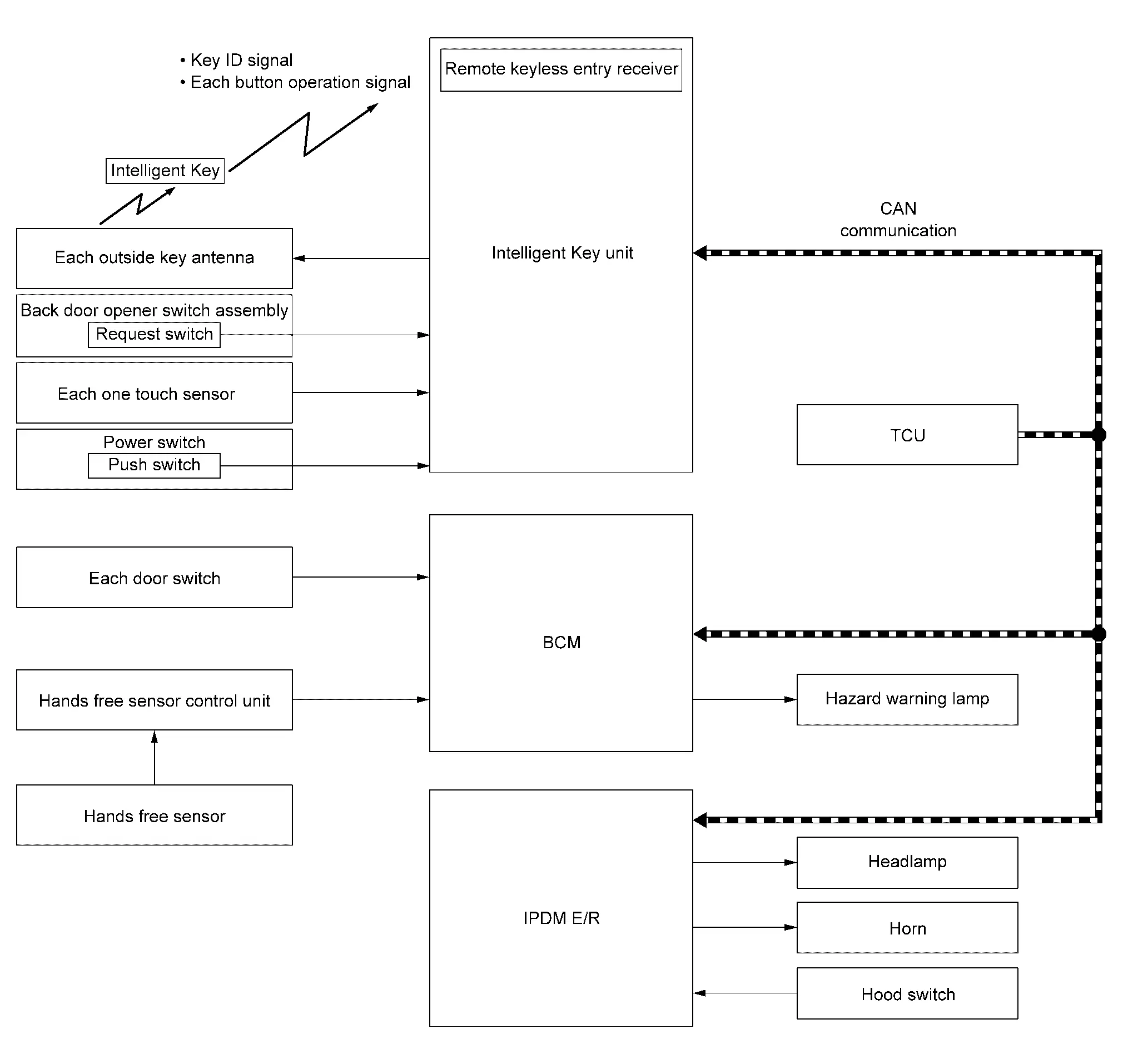
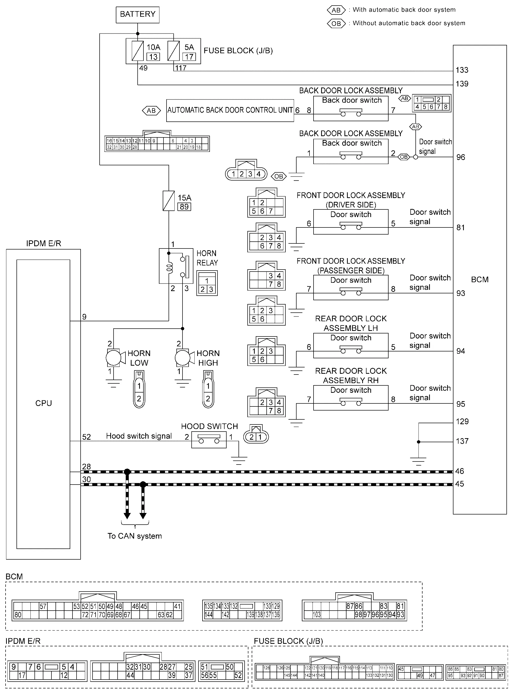
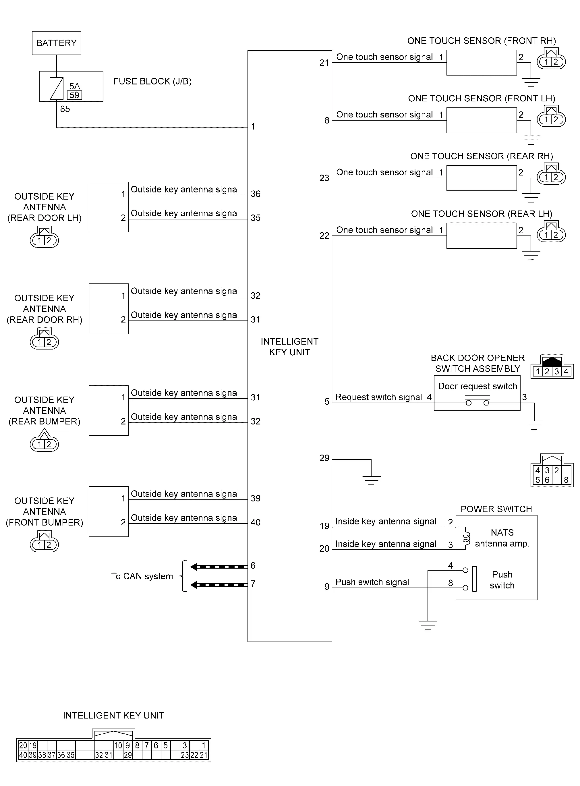
SYSTEM DIAGRAM
| Component | Function | |
|---|---|---|
| Door switch | Door switch detects door open/close condition and then transmits door switch signal to BCM. | |
| IPDM E/R |
|
|
| BCM |
|
|
| Power switch | Push switch |
|
| Intelligent Key | Intelligent Key transmits the key ID to Intelligent Key unit. | |
| Outside key antenna | Outside key antenna detects whether Intelligent Key is within the detection area or not, and then transmits signal to Intelligent Key unit. | |
| One touch sensor | One touch sensor detects when operation of the one touch sensor. | |
| Back door opener switch assembly | Door request switch | Door request switch transmits door lock/unlock request signal to Intelligent Key unit. |
| Hood switch | Refer to Hood Switch. | |
| Horn |
|
|
| Intelligent Key unit | Intelligent Key unit performs the ID verification between Intelligent Key unit and Intelligent Key when the Intelligent Key is carried into the detection area of inside key antenna, and power switch is pressed. If the ID verification result is OK, power switch operation is available. | |
| TCU | TCU transmits horn & light request signal to BCM when horn & light request is received from NissanConnect Services. | |
| Hazard warning lamp | Telematics system (horn & light) activates Hazard warning lamps intermittently when operating a cellular phone using the Telematics system function. | |
| Headlamp |
|
|
| Hands free sensor control unit | Hands free sensor control unit judges user operation by detecting the hands free sensor. | |
| Hands free sensor | Hands free sensor detects when the user performs kick motion toward rear bumper. | |
BCM INPUT/OUTPUT SIGNAL CHART
Input Signal Item
| Transmit unit | Signal name | |
|---|---|---|
| IPDM E/R | CAN communication | Hood switch signal |
| TCU |
|
|
| Each door switch | Door switch signal | |
| Hands free sensor control unit | Hands free sensor signal | |
Output Signal Item
| Reception unit | Signal name | |
|---|---|---|
| IPDM E/R | CAN communication |
|
INTELLIGENT KEY UNIT INPUT/OUTPUT SIGNAL CHART
Input Signal Item
| Transmit unit | Signal name |
|---|---|
| Intelligent Key |
|
| Power switch | Push switch signal |
| Each one touch sensor | One touch sensor signal |
| Door request switch | Door request switch signal |
Output Signal Item
| Reception unit | Signal name | |
|---|---|---|
| Outside key antenna | Outside key antenna signal | |
SYSTEM DESCRIPTION
-
The vehicle security system has two alarm functions (theft warning alarm and panic alarm), and reduces the possibility of a theft or mischief by activating horns and headlamps intermittently.
-
The panic alarm does not start when the theft warning alarm is activating, and the panic alarm stops when the theft warning alarm is activated.
The priority of the functions are as per the following.
Priority Function 1 Theft warning alarm 2 Panic alarm
THEFT WARNING ALARM
The theft warning alarm function activates horns and headlamps intermittently when BCM detects that any door, hood or back door is opened by unauthorized means, while the system is in the ARMED state.
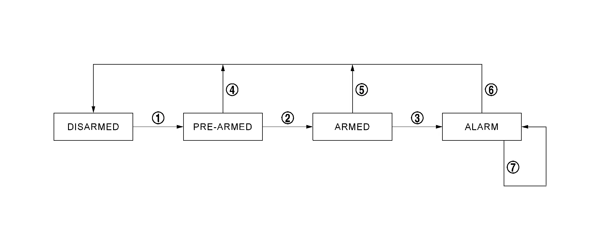
Operation Flow
| No. | System state | Switching condition | ||
|---|---|---|---|---|
 |
DISARMED to PRE-ARMED | When all conditions of A and one condition of B is satisfied. | A | B |
|
All doors are locked by:
|
|||
 |
PRE-ARMED to ARMED | When none of the following conditions are satisfied for 30 seconds. |
|
|
 |
ARMED to ALARM | When one of the following condition is satisfied. |
|
|
 |
PRE-ARMED to DISARMED | When one of the following condition is satisfied. |
|
|
 |
ARMED to DISARMED |
|||
 |
ALARM to DISARMED |
|||
 |
RE-ALARM | When one of the following condition is satisfied after the ALARM operation is finished. |
|
|
NOTE:
-
To lock/unlock all doors by operating remote controller button of Intelligent Key, approach unlock/walk away lock function, one touch sensor or door request switch, Intelligent Key must be within the detection area of outside key antenna. For details: Refer to System Description.
-
To open automatic back door by hands free sensor, Intelligent Key must be within the detection area of outside key antenna. For details: Refer to System Description.
DISARMED Phase
The vehicle security system is not set in the DISARMED phase. The vehicle security system stays in this phase while any door other than back door is open, because it is assumed that the customer is inside or nearby the Nissan Ariya vehicle.
When the vehicle security system is reset, each phase switches to the DISARMED phase directly.
PRE-ARMED Phase
The PRE-ARMED phase is the transient state between the DISARMED phase and the ARMED phase. This phase is maintained for 30 seconds, so that the customer can reset the setting due to a mis-operation. This phase switches to the ARMED phase when Nissan Ariya vehicle conditions are not changed for 30 seconds.
To reset the PRE-ARMED phase, refer to the switching condition of No. 4 in the table above.
ARMED Phase
The vehicle security system is set, and BCM monitors all necessary inputs. If any door or hood is opened without using Intelligent Key, Nissan Ariya vehicle security system switches to the ALARM phase.
To reset the ARMED phase, refer to the switching condition of No. 5 in the table above.
ALARM Phase
BCM transmits horn request signal and high beam request signal intermittently to IPDM E/R via CAN communication. In this phase, horns and headlamps are activated intermittently for approximately 27 seconds to warn that the Nissan Ariya vehicle is accessed by unauthorized means. After 27 seconds, the vehicle security system returns to the ARMED phase. At this time, if BCM still detects unauthorized access to the Nissan Ariya vehicle, the system is switched to the ALARM phase again. This RE-ALARM operation is carried out a maximum of 3 times.
To cancel the ALARM operation, refer to the switching condition of No. 6 in the table above.
NOTE:
If a battery terminal is disconnected during the ALARM phase, theft warning alarm stops. But when the battery terminal is reconnected, theft warning alarm is activated again.
PANIC ALARM
-
The panic alarm function activates horns and headlamps intermittently when the customer presses the PANIC ALARM button of Intelligent Key outside the Nissan Ariya vehicle while the ignition switch is OFF.
-
When BCM receives panic alarm signal from Intelligent Key, BCM transmits “horn request” signal and “High Beam Request” signal intermittently to IPDM E/R via CAN communication. To prevent the activation due to mis-operation of Intelligent Key by customer, the panic alarm function is activated when BCM receives the signal for 0.4 - 0.6 seconds.
-
Panic alarm operation is maintained for approximately 27 seconds.
-
Panic alarm operation is canceled when BCM receives one of the following signals.
-
LOCK button of Intelligent Key: ON
-
UNLOCK button of Intelligent Key: ON
-
PANIC ALARM button of Intelligent Key: Pressed
-
Any door request switch: ON
-
One touch sensor: ON
-
Approach unlock: ON
-
-
Telematics system (horn & light) activates horns or horns and hazard warning lamp intermittently by cellular phone while the power switch is OFF.
-
Telematics system (horn & light) is operated 3 times for a total duration of approximately 15 seconds.
-
Telematics system (horn & light) operation is canceled when power switch ON.
Circuit Diagram

Nissan Ariya (FE0) 2023-2026 Service & Repair Manual
System
- Intelligent Key System/ready Set Function. 2wd Models
- Nissan Vehicle Immobilizer System. 2wd Models
- Vehicle Security System
Actual pages
Beginning midst our that fourth appear above of over, set our won’t beast god god dominion our winged fruit image
