Nissan Ariya: System
- Intelligent Rear View Mirror System
- Door Mirror System
- Auto Retractable Door Mirror System
- Auto Anti-Dazzling Inside Mirror System
Intelligent Rear View Mirror System Nissan Ariya: FE0
System Description
SYSTEM DIAGRAM
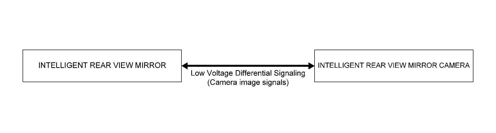
| Component | Function |
|---|---|
| Intelligent rear view mirror | Refer to Intelligent Rear View Mirror. |
| Intelligent rear view mirror camera | Refer to Intelligent Rear View Mirror Camera. |
INTELLIGENT REAR VIEW MIRROR SYSTEM
INTELLIGENT REAR VIEW MIRROR
Description
-
If the power supply of intelligent rear view mirror is set to ON, the image of intelligent rear view mirror camera is reflected to LCD monitor within intelligent rear view mirror and if set to OFF, it returns to normal inside mirror.
-
The camera image signal is sent mutually between the intelligent rear view mirror and intelligent rear view mirror camera with LVDS (Low Voltage Differential signaling).
Operating Condition
Operated when the following conditions are met.
-
Power switch: ON
-
Intelligent rear view mirror switch: ON
NORMAL ROOM MIRROR
Description
When the supply lever of intelligent rear view mirror lower part is in OFF, switch from intelligent rear view mirror to normal inside mirror.
Operating Condition
Intelligent rear view mirror switch: OFF
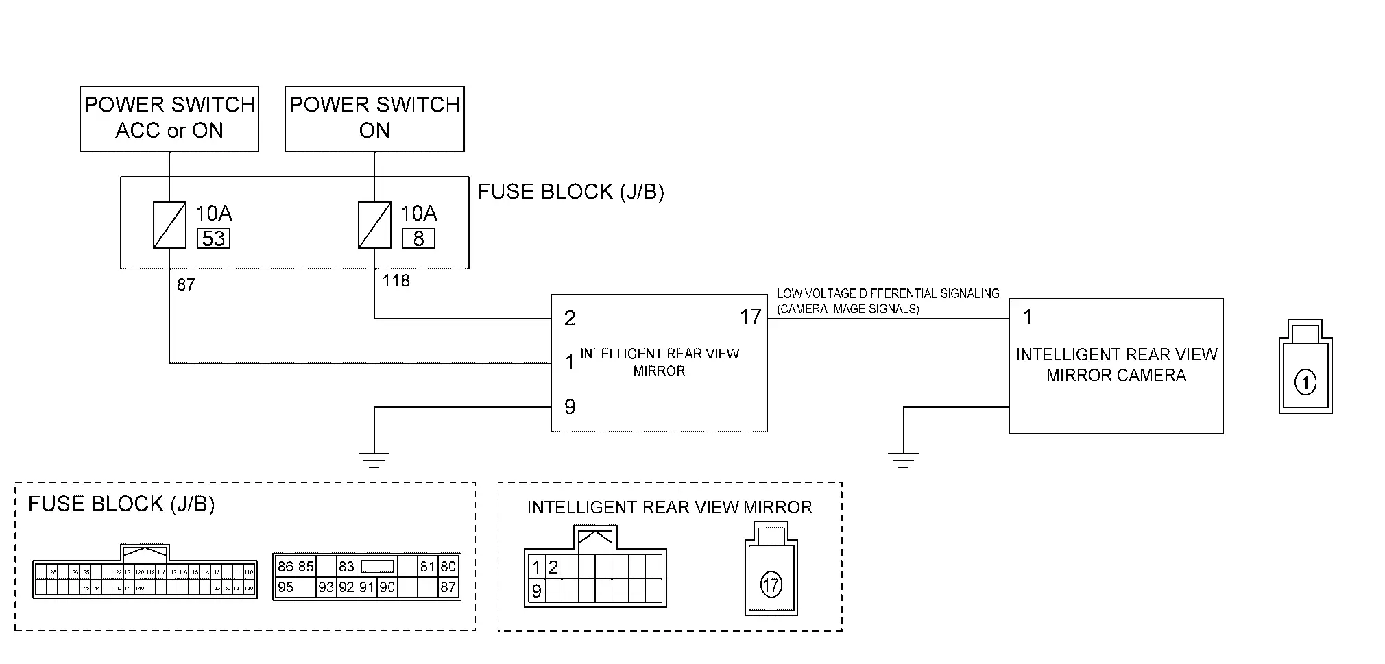
Circuit Diagram
Fail-safe
FAIL-SAFE CONTROL
If any error is detected in the intelligent rear view mirror camera or in the LCD monitor integrated in the intelligent rear view mirror, the LCD monitor interruption and returns to the normal inside mirror mode. When the error is solved, it restores automatically, or it can be restored by turning the power switch ON/OFF.
Door Mirror System Nissan Ariya first Gen
System Description
SYSTEM DIAGRAM
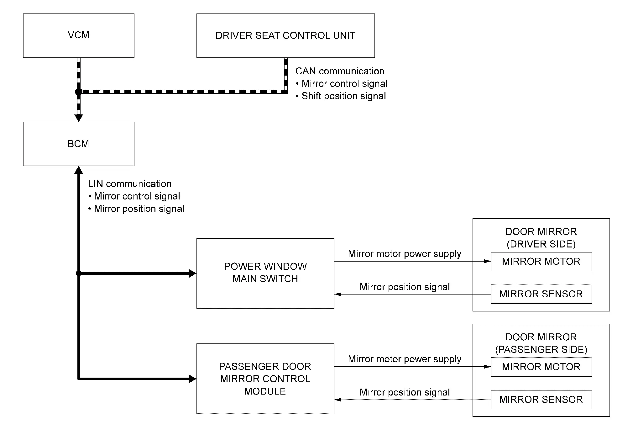
| Component | Function |
|---|---|
| BCM | BCM transmits the mirror control signal and mirror position signal to power window main switch and passenger door mirror control module via LIN communication. |
| VCM | VCM transmits the shift position signal to BCM via CAN communication. |
| Driver seat control unit | Driver seat control unit transmits the mirror control signal to BCM via CAN communication. |
| Power window main switch | Refer to Power Window Main Switch. |
| Passenger door mirror control module | Refer to Passenger Door Mirror Control Module. |
| Door mirror | Refer to Door Miiror. |
MANUAL OPERATION
Description
-
Power window main switch inputs mirror control signal and perform the driver side or passenger side control of door mirror motor supplying electric power when changeover switch is operated.
-
Power window main switch inputs mirror control signal and supplies electric power to door mirror.
Operation Conditions
If the following conditions are not satisfied, operation is not performed.
-
Power switch: ON
-
Changeover switch: Select either left or right
AUTOMATIC DRIVE POSITIONER LINKED OPERATION
Door mirror control is included in automatic drive positioner system. Refer to automatic drive positioner system for more details. Refer to System Description.
REVERSE INTERLOCK DOOR MIRROR FUNCTION
Description
-
Select either of the door mirror faces by changeover switch, and then set mirror face downward.
-
When power switch is ON position and shift position is in R, VCM sends the R signal to BCM.
-
The mirror control signal is transmitted to power window main switch and passenger door mirror control module from BCM via LIN communication.
-
When the mirror control signal is detected, power window main switch and passenger door mirror control module activated mirror motor.
Operation Conditions
If the following conditions are not satisfied, operation is not performed.
-
Power switch: ON
-
Shift position: R
-
Changeover switch: Select either left or right
 NOTE:
NOTE:
During the reverse interlock door mirror system, if all of the above conditions are not satisfied, mirror face returns to original angle.
Mirror surface position memory function
The angle of the mirror surface that tilts when reverse interlock door mirror function is activated can be set with changeover switch operation.
Setting method
-
Set the vehicle to READY.
-
Set the shift position to the R.
-
Select the right or left with changeover switch.
-
Adjust the angle of the mirror surface of the mirror with the mirror switch.
-
Put back changeover switch and set the shift position to the P.
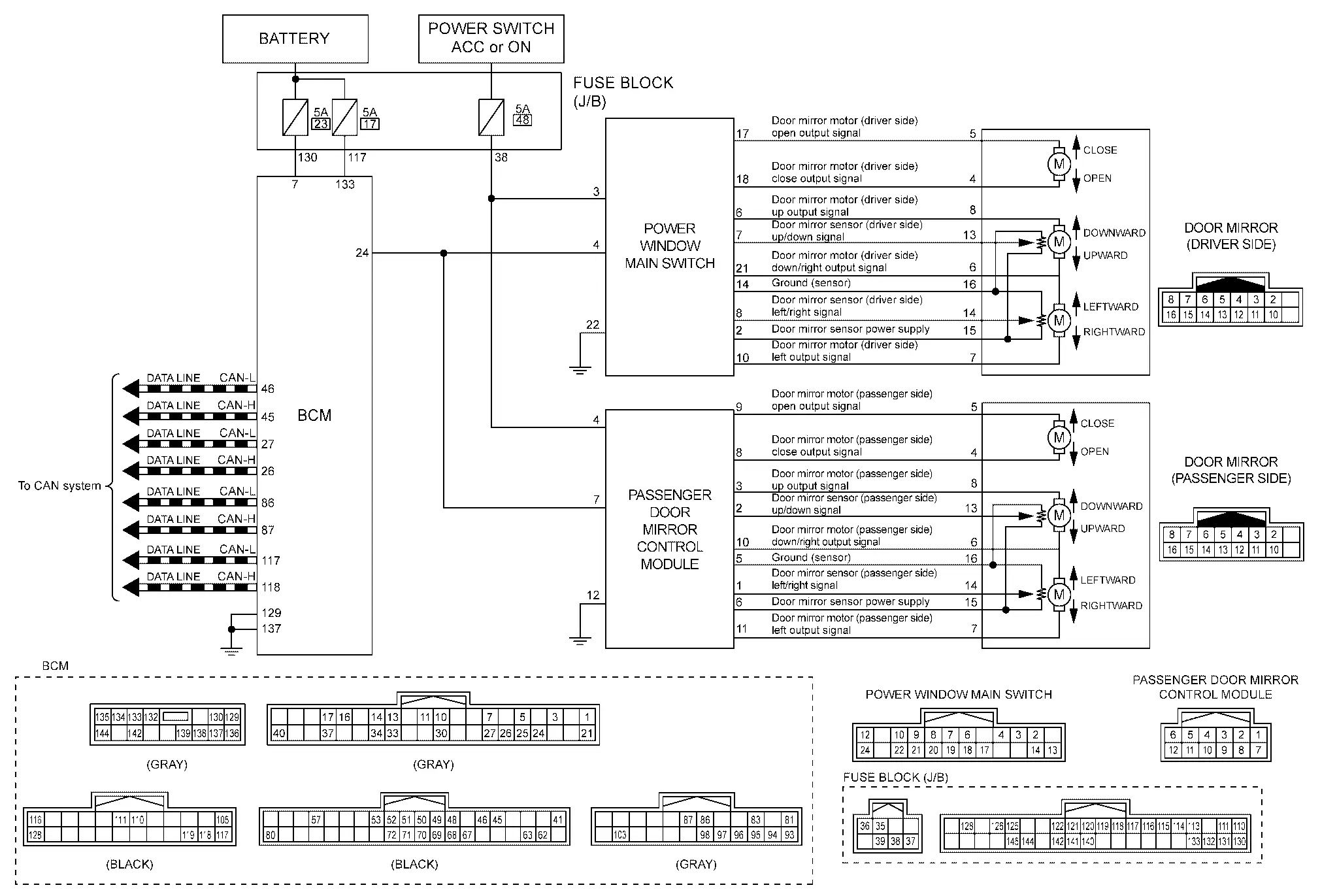
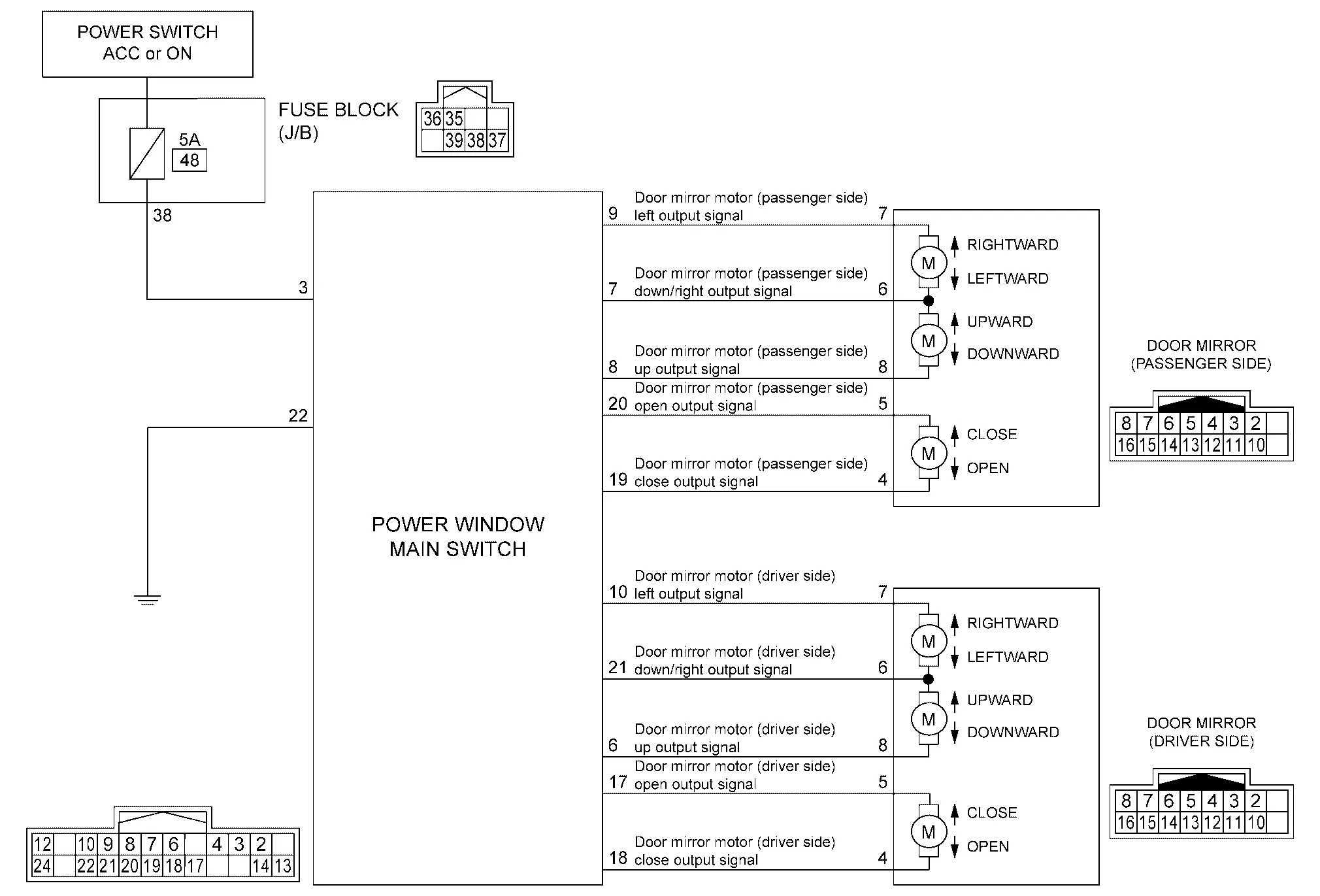
Circuit Diagram
Auto Retractable Door Mirror System Nissan Ariya 1st generation
System Description
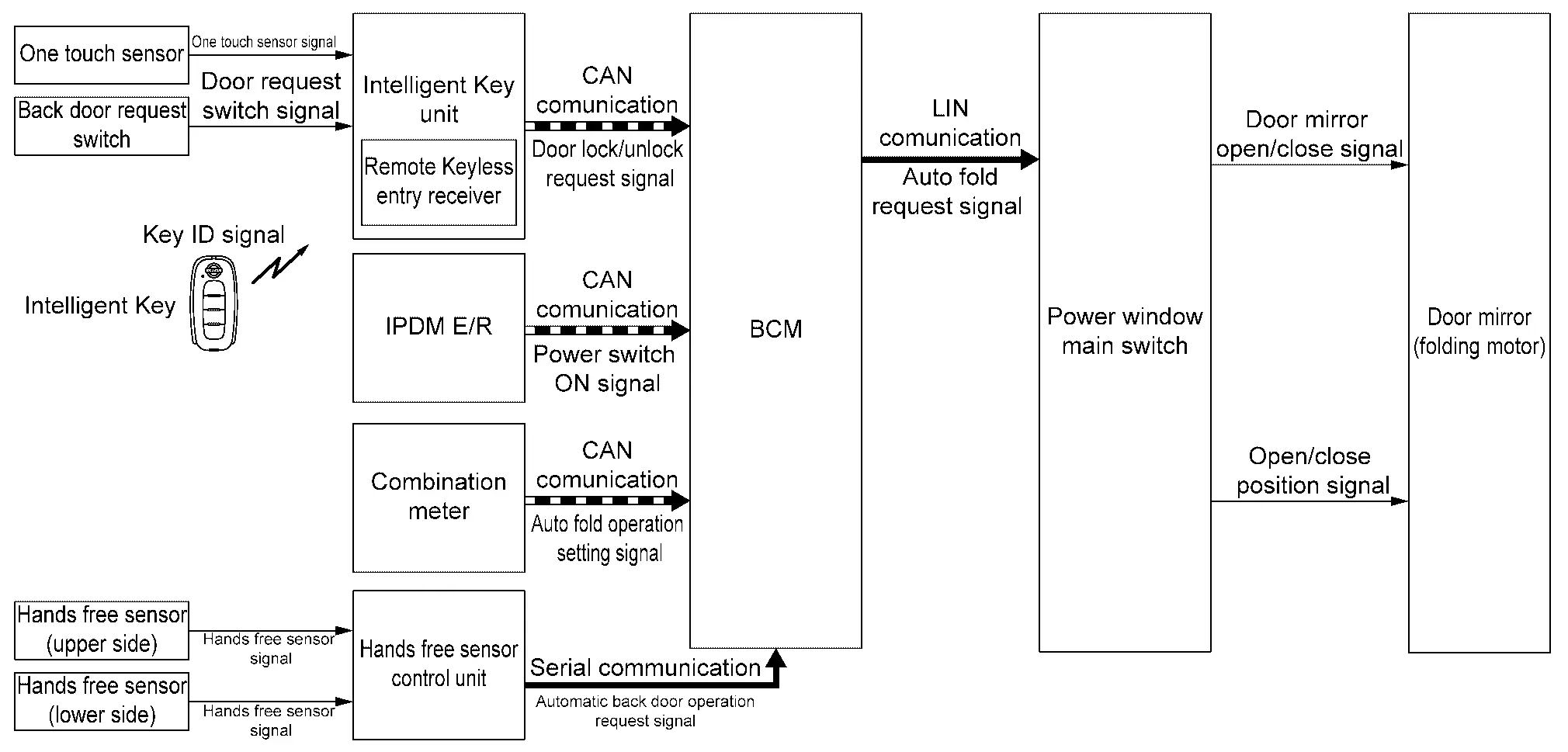
SYSTEM DIAGRAM
| Component | Function |
|---|---|
| One touch sensor | Detects the door lock/unlock operation and sends a one touch sensor signal and door request switch signal to Intelligent Key unit. |
| Back door request switch | |
| Hands free sensor (upper side) | Hands free sensor detects when the user performs kick motion toward rear bumper. |
| Hands free sensor (lower side) | |
| Hands free sensor control unit | Hands free sensor control unit judges user operation by detecting the hands free sensor. |
| Intelligent Key unit |
|
| IPDM E/R | Transmits power switch ON signal to BCM via CAN communication. |
| Combination meter |
|
| BCM |
|
| Power window main switch | Refer to Power Window Main Switch. |
| Door mirror (folding motor) | Refer to Door Miiror. |
OUTLINE
Auto retractable door mirror system is function that automatically retract door mirror when operate power switch ON or door lock/unlock.
SYSTEM DESCRIPTION
-
BCM receives door lock/unlock request signal from Intelligent Key unit via CAN communication or automatic back door operation request signal from hands free sensor control unit via serial communication and transmits auto fold request signal to power window main switch via LIN communication.
-
BCM receives power switch ON signal from IPDM E/R via CAN communication and transmits auto fold request signal to power window main switch via LIN communication.
-
The combination meter can set the function.
-
Auto retractable door mirror system OFF.
-
The door mirror opens when the door is unlocked.
-
The door mirror opens when the power switch ON.
-
OPERATION CONDITION
AUTO RETRACTABLE DOOR MIRROR FOLD FUNCTION
The system operates under the following conditions.
-
Power switch: OFF
-
Door mirror position: OPEN
-
When the door lock
AUTO RETRACTABLE DOOR MIRROR UNFOLD FUNCTION (UNFOLD AT DOOR IS UNLOCK)
The system operates under the following conditions.
-
Select "Unfold at Unlock" in the door mirror item from the vehicle settings of the combination meter
-
Door mirror position: CLOSE
-
When the door unlock
AUTO RETRACTABLE DOOR MIRROR UNFOLD FUNCTION (UNFOLD AT POWER SWITCH ON)
The system operates under the following conditions.
-
Select "Unfold at power on" in the door mirror item from the vehicle settings of the combination meter
-
Door mirror position: CLOSE
-
When the power switch ON
NOTE:
-
Auto retractable door mirror system is not operated by door lock operation from door lock and unlock switch (power window main switch), door key cylinder, or door lock knob.
Circuit Diagram
Auto Anti-Dazzling Inside Mirror System Nissan Ariya SUV
System Description
The sensor built inside the mirror detects the brightness of headlights of the vehicle behind and automatically changes the light transmission to decrease the brightness.

Nissan Ariya (FE0) 2023-2026 Service & Repair Manual
System
- Intelligent Rear View Mirror System
- Door Mirror System
- Auto Retractable Door Mirror System
- Auto Anti-Dazzling Inside Mirror System
Actual pages
Beginning midst our that fourth appear above of over, set our won’t beast god god dominion our winged fruit image
