Nissan Ariya: System
- Front Wiper and Washer System (with Light and Rain Sensor)
- Rear Wiper and Washer System
- Information Display (combination Meter)
- Warning/indicator/chime List
Front Wiper and Washer System (with Light and Rain Sensor) Nissan Ariya 2023
System Description
SYSTEM DIAGRAM
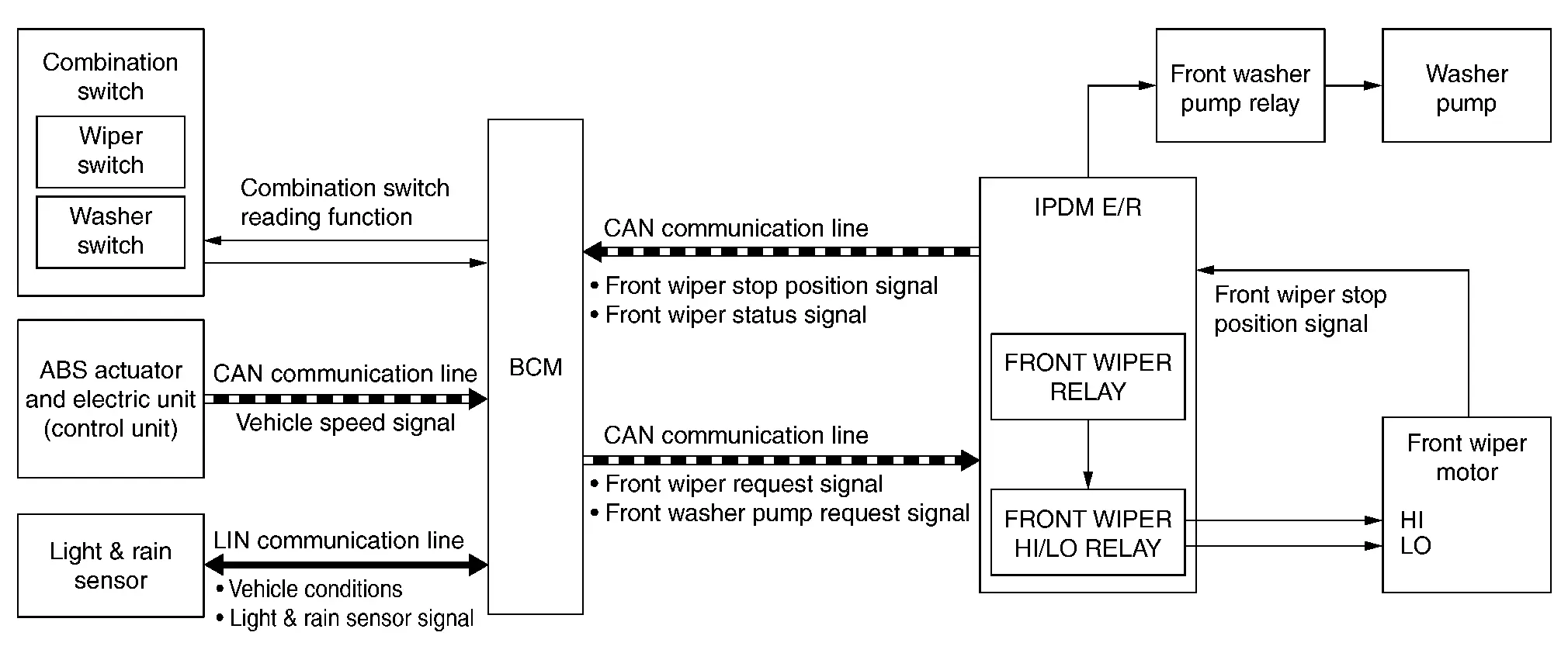
| Component | Function | |
|---|---|---|
| Front wiper motor | Refer to Front Wiper Motor.. | |
| IPDM E/R | Controls integrated relays according to the request (via CAN communication) from BCM. | |
| BCM |
|
|
| Combination switch (wiper & washer switch) | Wiper switch | Transmits the status of the combination switch to BCM. |
| Washer switch | ||
| Front washer pump relay | Controls washer pump according to the request from IPDM E/R. | |
| ABS actuator and electric unit (control unit) | Transmits Nissan Ariya vehicle speed signal to BCM via CAN communication. | |
| Washer pump | Refer to Washer pump. | |
| Light & rain sensor | Refer to Light And Rain Sensor. | |
OUTLINE
The front wiper is controlled by each function of BCM and IPDM E/R.
Control by BCM
-
Combination switch reading function
-
Front wiper control function
-
Front washer pump control function
Control by IPDM E/R
-
Front wiper control function
-
Relay control function
-
Front washer pump control function
FRONT WIPER BASIC OPERATION
-
BCM detects the combination switch condition by the combination switch reading function.
-
BCM transmits the front wiper request signal to IPDM E/R via CAN communication depending on each operating condition of the front wiper.
-
IPDM E/R turns ON/OFF the integrated front wiper relay and the front wiper HI/LO relay according to the front wiper request signal. IPDM E/R provides the power supply to operate the front wiper HI/LO operation.
FRONT WIPER LO OPERATION
-
BCM transmits the front wiper request signal (LOW) to IPDM E/R via CAN communication according to the front wiper LO operating condition.
Front wiper LO operating condition
-
Power switch ON
-
Front wiper switch LO or front wiper switch MIST (while pressing)
-
-
IPDM E/R turns ON the integrated front wiper relay according to the front wiper request signal (LOW).
FRONT WIPER HI OPERATION
-
BCM transmits the front wiper request signal (HIGH) to IPDM E/R via CAN communication according to the front wiper HI operating condition.
Front wiper HI operating condition
-
Power switch ON
-
Front wiper switch HI
-
-
IPDM E/R turns ON the integrated front wiper relay and the front wiper HI/LO relay according to the front wiper request signal (HIGH).
FRONT WIPER AUTO OPERATION
 NOTE:
NOTE:
When the rain sensor is set ON with the Nissan Ariya vehicle settings in the vehicle information display of the combination meter the front wiper auto operation is activated.
The light & rain sensor change the front wiper operating speed according to the detected rain conditions and Nissan Ariya vehicle conditions.
Rain Detection
Rain level and sensor conditions are detected by light & rain sensor.
-
BCM transmits the vehicle conditions (vehicle speed, front wiper condition, light & rain sensor sensitivity setting, etc.) to the light & rain sensor via the LIN communication line.
-
Light & rain sensor judges a wiping speed for front wiper by rain condition and the Nissan Ariya vehicle conditions. And it transmits the light & rain sensor signal to the BCM via the light & rain sensor LIN communication line.
Auto Wiping Operation
-
BCM receives the light & rain sensor signal from the light & rain sensor via the LIN communication line.
-
BCM controls front wiper operation according to the wiping speed request signal. And it transmits the front wiper request signal (LOW or HIGH) to the IPDM E/R via CAN communication line.
Front wiper AUTO operating condition
-
Power switch ON
-
Front wiper switch AUTO
-
NOTE:
When the front wiper switch is turned to AUTO position, front wiper operates once regardless of rainy conditions.
BCM determines light & rain sensor sensitivity according to wiper volume dial position.
| Wiper volume dial position | Sensitivity |
|---|---|
| 1 | Low sensitivity |
| 2 | Low−medium sensitivity |
| 3 | Medium−high sensitivity |
| 4 | High sensitivity |
NOTE:
When the wiper volume dial position is turned up by 1 level under front wiper AUTO operating condition, front wiper operates once.
Splash mode operation
Front wiper is operated at HI regardless of the wiper volume adjustment position, when water drops are instantaneously sprayed over the windshield glass due to water splash from oncoming Nissan Ariya vehicles or other causes. After that, AUTO operation is performed depending on the amount of water drops.
SPLASH MODE OPERATION CONDITIONS
-
Front wiper switch AUTO
-
Power switch ON
NOTE:
Splash mode is not operated and auto wiping operation is performed, while the Nissan Ariya vehicle is stopped.
FRONT WIPER INT OPERATION
NOTE:
When the rain sensor is set OFF with the Nissan Ariya vehicle settings in the vehicle information display of the combination meter the front wiper INT operation is activated.
-
BCM transmits the front wiper request signal (LOW) to IPDM E/R via CAN communication depending on the front wiper INT operating condition and intermittent operation delay interval according to the wiper volume dial position.
Front wiper INT operating condition
-
Power switch ON
-
Front wiper switch AUTO
-
-
IPDM E/R turns ON the integrated front wiper relay so that the front wiper is operated only once according to the front wiper request signal (LOW) and front wiper request signal (RETURN).
-
BCM detects stop position/except stop position of the front wiper motor according to the front wiper stop position signal received from IPDM E/R via CAN communication.
-
BCM transmits the front wiper request signal (LOW) again after the intermittent operation delay interval.
NOTE:
The front wiper INT operation setting can change linked with Nissan Ariya vehicle speed ON or OFF in the vehicle settings in the vehicle information display of the combination meter.
Front wiper intermittent operation with vehicle speed
-
BCM calculates the intermittent operation delay interval from the following
-
Nissan Ariya Vehicle speed signal
-
Wiper volume dial position
-
Intermittent operation delay Interval
Unit: Second
| Intermittent operation interval | Nissan Ariya Vehicle speed | ||||
| Accelerating |
0 – 5 km/h (0 – 3.1 MPH) |
5 – 65 km/h (3.1 – 40.4 MPH) |
65 km/h (40.4 MPH) or more |
||
| Decelerating |
0 – 2 km/h (0 – 1.2 MPH) |
2 – 60 km/h (1.2 – 37.3 MPH) |
60 km/h (37.3 MPH) or more |
||
|
Long ↑ ↓ Short |
Wiper volume dial position | 1 | 21.0 | 7.5 | 4.5 |
| 2 | 11.2 | 4.0 | 2.4 | ||
| 3 | 5.6 | 2.0 | 1.2 | ||
| 4 | 2.8 | 1.0 | 0.6 | ||
Unit: Second
| Intermittent operation interval | |||
|
Long ↑ ↓ Short |
Wiper volume dial position | 1 | 15.0 |
| 2 | 8.0 | ||
| 3 | 4.0 | ||
| 4 | 2.0 | ||
FRONT WIPER AUTO STOP OPERATION
-
BCM transmits the front wiper request signal (RETURN) to IPDM E/R via CAN communication when the front wiper switch is turned OFF.
-
IPDM E/R detects the front wiper stop position signal from the front wiper motor to find out the front wiper motor position (stop position/except stop position).
-
When IPDM E/R receives the front wiper request signal (RETURN) from BCM and the front wiper motor position is not in the stop position, IPDM E/R turns ON the front wiper relay until the front wiper motor returns to the stop position.
-
When the front wiper motor returns to the stop position, IPDM E/R transmits front wiper status signal to BCM via CAN communication.
-
When BCM receives front wiper status signal from IPDM E/R, BCM transmits the front wiper request signal (STOP) to IPDM E/R via CAN communication.
FRONT WIPER OPERATION LINKED WITH WASHER
-
BCM transmits the front wiper request signal (LOW) to IPDM E/R via CAN communication according to the washer linked operating condition of the front wiper.
-
BCM transmits the front wiper request signal (LOW) so that the front wiper operates approximately 2 times when the front washer switch OFF is detected.
Washer linked operating condition of front wiper
-
Power switch ON
-
Front washer switch ON
-
-
IPDM E/R turns ON the integrated front wiper relay according to the front wiper request signal (LOW).
-
BCM transmits the front washer pump request signal to IPDM E/R via CAN communication depending on operating condition.
-
IPDM E/R turns ON /OFF the front washer relay according to the front washer pump request signal. IPDM E/R provides the power supply to operate the washer pump.
WIPER LINKED AUTO LIGHTING FUNCTION
When lighting switch is in the AUTO position, front wiper operates, and then headlamp ON. Refer to System Description.
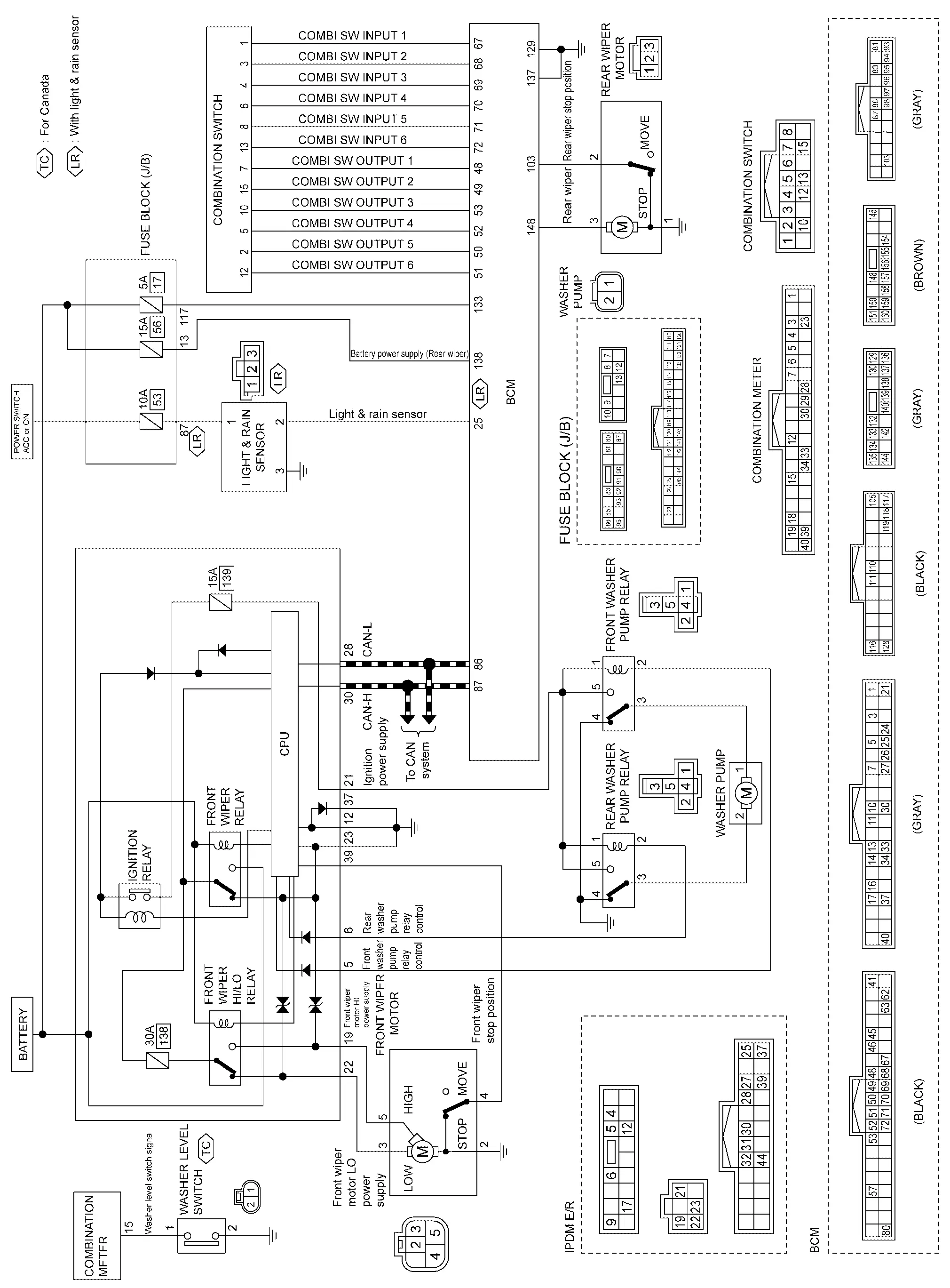
Circuit Diagram
Fail-safe
IPDM E/R
CAN COMMUNICATION CONTROL
When CAN communication with VCM and BCM is impossible, IPDM E/R performs fail-safe control. After CAN communication recovers normally, it also returns to normal control.
| Control part | Fail-safe operation |
|---|---|
| Front wiper |
|
FRONT WIPER CONTROL
IPDM E/R detects front wiper stop position by front wiper stop position signal.
When front wiper stop position signal is in the condition listed below while the front wiper is operating, IPDM E/R activates the fail-safe.
| Power switch | Front wiper switch | Front wiper stop position signal | Fail-safe |
|---|---|---|---|
| ON | OFF | The signal does not change from the battery voltage for 10 seconds. | Stops front wiper power supply for 20 seconds |
| Except OFF | The signal does not change for 10 seconds. |
Rear Wiper and Washer System Nissan Ariya 2026
System Description
SYSTEM DIAGRAM
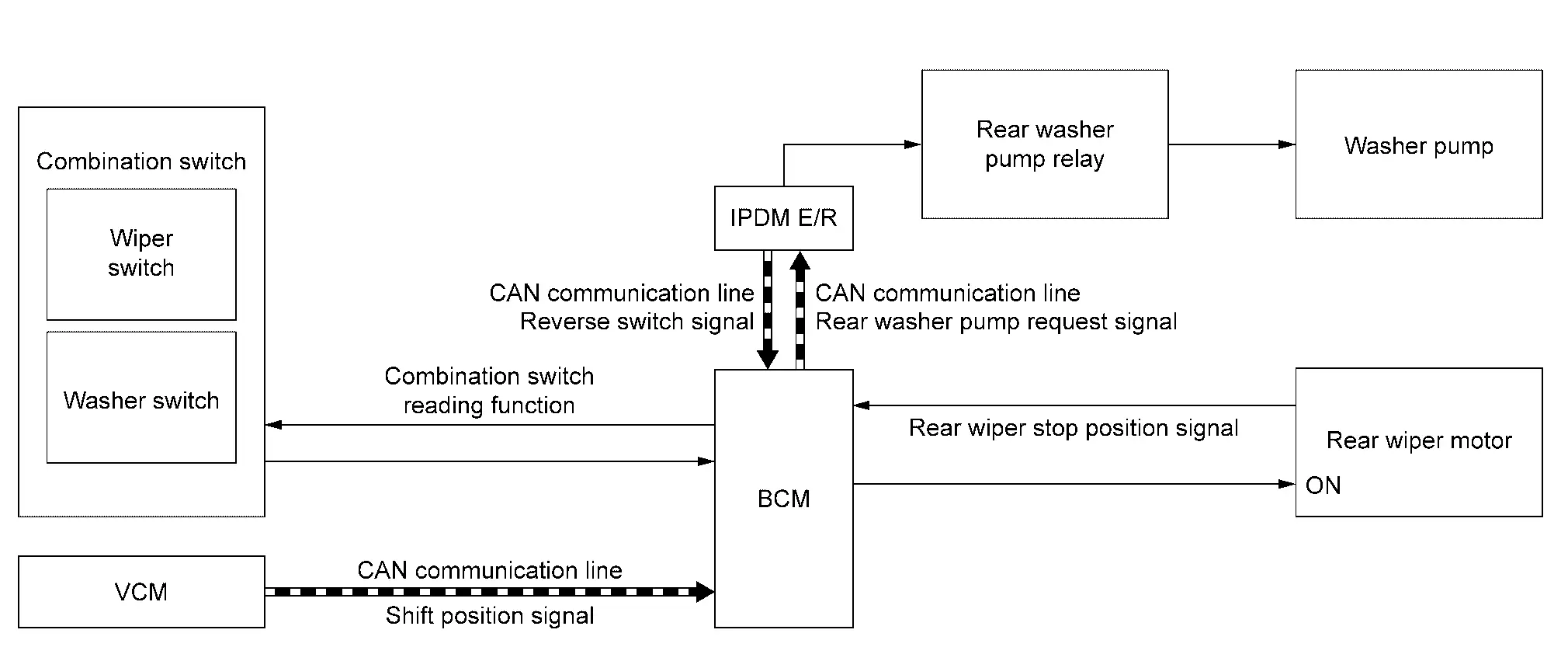
| Component | Function | |
|---|---|---|
| Rear wiper motor | Refer to Rear Wiper Motor. | |
| IPDM E/R | Controls rear washer pump relay according to the request (via CAN communication) from BCM. | |
| BCM | Supplies power to the rear wiper motor | |
| Combination switch (wiper & washer switch) | Wiper switch | Transmits the status of the combination switch to BCM. |
| Washer switch | ||
| Rear washer pump relay | Controls washer pump according to the request from IPDM E/R. | |
| Washer pump | Refer to Washer pump. | |
| VCM | Transmits the shift position signal to BCM. | |
OUTLINE
The rear wiper is controlled by each function of BCM.
Control by BCM
-
Combination switch reading function
-
Rear wiper control function
-
Rear washer pump control function
Control by IPDM E/R
-
Rear wiper control function
-
Rear washer pump control function
REAR WIPER BASIC OPERATION
-
BCM detects the combination switch condition by the combination switch reading function.
-
BCM controls the rear wiper to start or stop.
REAR WIPER ON OPERATION
BCM supplies power to the rear wiper motor according to the rear wiper ON operating condition.
Rear wiper ON operating condition
-
Power switch ON
-
Rear wiper switch ON
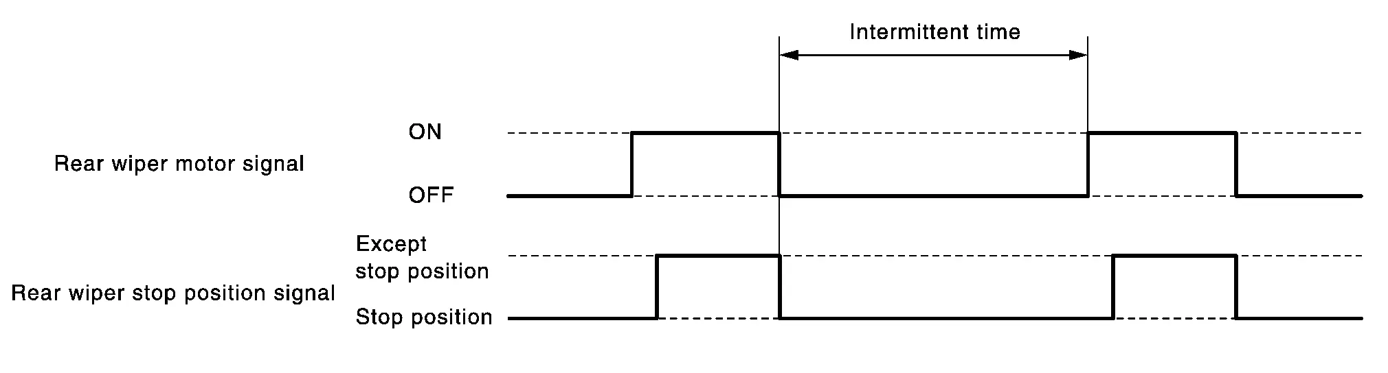
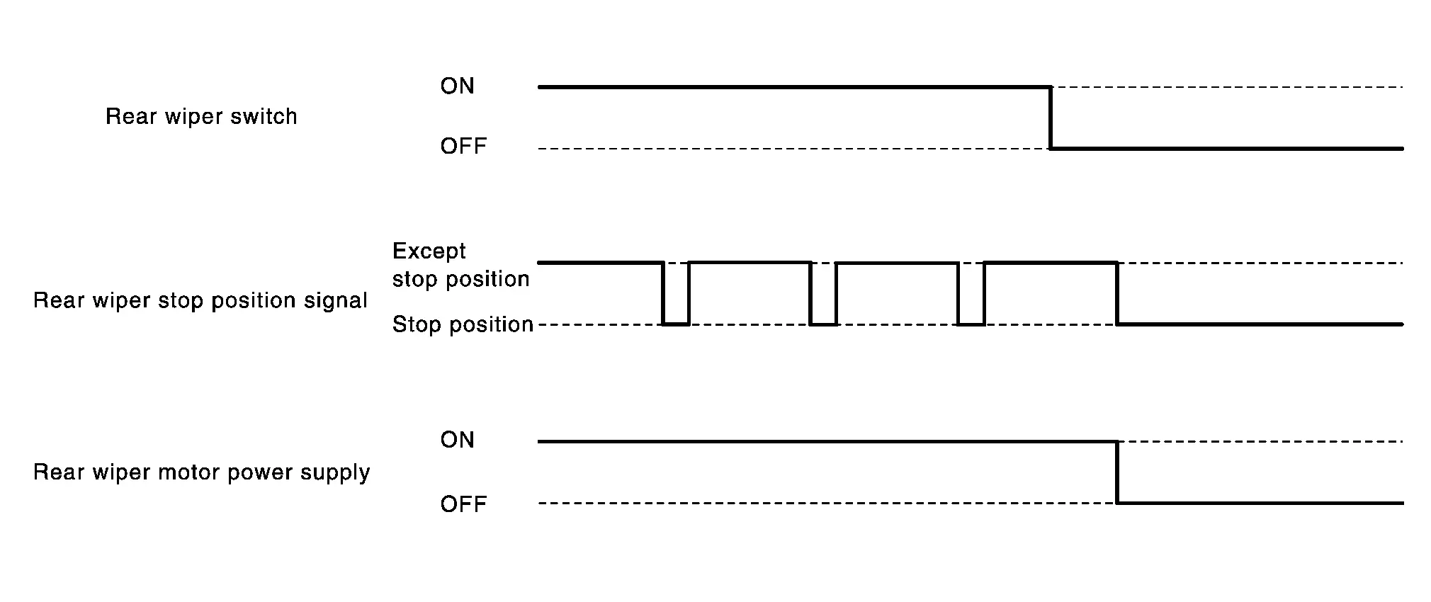
REAR WIPER INT OPERATION
-
BCM supplies power to the rear wiper motor according to the INT operating condition.
Rear wiper INT operating condition
-
Power switch ON
-
Rear wiper switch INT
-
-
BCM controls the rear wiper to operate once.
-
BCM detects the rear wiper motor stop position.
-
BCM supplies power to the rear wiper motor after an intermittent from the stop of the rear wiper motor.
REAR WIPER AUTO STOP OPERATION
-
BCM stops supplying power to the rear wiper motor when the rear wiper switch is turned OFF.
-
BCM reads a rear wiper stop position signal from the rear wiper motor to detect a rear wiper motor position.
-
When the rear wiper motor is at other than the stopping position, BCM continues to supply power to the rear wiper motor until it returns to the stop position.
NOTE:
BCM stops supplying power to the rear wiper motor when the power switch is turned OFF.
REAR WIPER OPERATION LINKED WITH WASHER
-
BCM supplies power to the rear wiper motor according to the washer linked operating condition of rear wiper. When the rear washer switch is turned OFF, BCM controls rear wiper to operate approximately 3 times.
Washer linked operating condition of rear wiper
-
Power switch ON
-
Rear washer switch ON
-
-
BCM transmits the rear washer pump request signal to IPDM E/R via CAN communication depending condition.
-
IPDM E/R turns ON/OFF the rear washer pump relay according to the rear washer pump request signal. IPDM E/R provides the power supply to operate the washer pump.
REAR WIPER OPERATION LINKED WITH REVERSE
-
BCM controls rear wiper to INT operating according to the conditions of rear wiper operation linked with reverse.
Condition of rear wiper operation linked with reverse
-
Power switch ON
-
Front wiper switch: LO, HI, INT or AUTO
-
Rear wiper switch OFF
-
Selector lever “R”
-
-
When selector lever is selected to “R”, VCM transmits reverse switch signal to BCM via CAN communication, and then operates rear wiper motor.
NOTE:
The rear wiper operation linked with reverse can be set to ON or OFF changed by Nissan Ariya vehicle setting in the vehicle information display of the combination meter setting.
Circuit Diagram
Information Display (combination Meter) Nissan Ariya first Gen
Washer Fluid Warning
NOTE:
Washer level switch is only applied in Canada.
DESIGN/PURPOSE
Washer fluid warning reminds driver the washer fluid is insufficient.
| Symbol | Message |
|---|---|
|
|
Low Washer Fluid |

SYNCHRONIZATION WITH MASTER WARNING LAMP
Not applicable
SYSTEM DIAGRAM
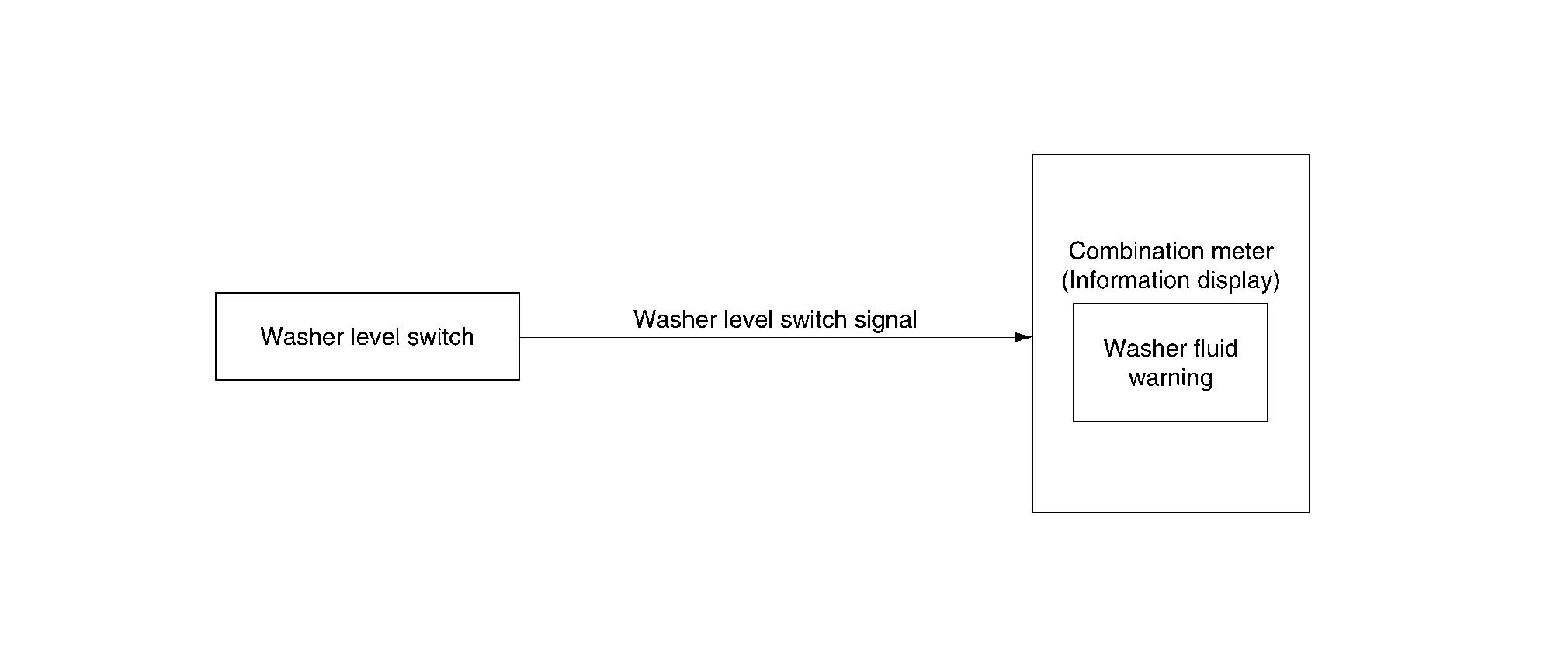
SIGNAL PATH
-
When washer fluid level is low, washer level switch turns ON and transmits washer level switch signal to combination meter.
-
Combination meter display washer fluid warning according to washer level switch signal.
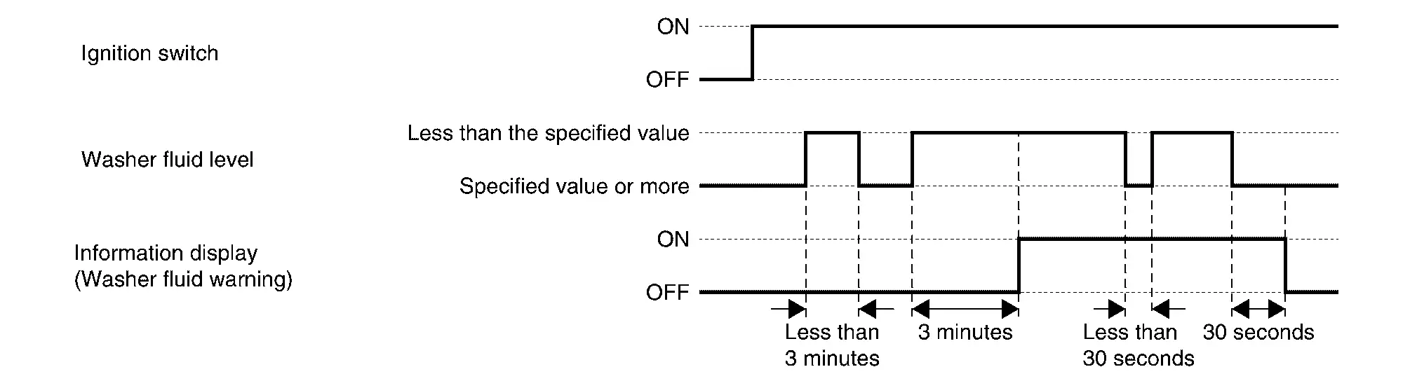
WARNING/INDICATOR OPERATING CONDITION
When all of the conditions listed below are satisfied:
-
Ignition switch is ON.
-
Washer fluid is insufficient. (Washer level switch is ON and 3 minutes are passed)
WARNING/INDICATOR CANCEL CONDITION
When any of the condition listed below is satisfied:
-
Ignition switch is OFF.
-
After refill the washer fluid. (Washer level switch is OFF and 30 seconds are passed)
TIMING CHART
Warning/indicator/chime List Nissan Ariya first Gen
Warning/Indicator (Information Display)
| Item | Reference |
|---|---|
|
Washer fluid warning (Only applied in Canada) |
Refer to Washer Fluid Warning. |

Nissan Ariya (FE0) 2023-2026 Service & Repair Manual
System
- Front Wiper and Washer System (with Light and Rain Sensor)
- Rear Wiper and Washer System
- Information Display (combination Meter)
- Warning/indicator/chime List
Actual pages
Beginning midst our that fourth appear above of over, set our won’t beast god god dominion our winged fruit image
