Nissan Ariya: System
- Body Control System
- Combination Switch Reading System
- Signal Buffer System
- Power Consumption Control System
- Shipping Mode Control System
Body Control System Nissan Ariya
System Description
OUTLINE
-
BCM (Body Control Module) controls the various electrical components. It inputs the information required to the control from CAN communication and the signal received from each switch and sensor.
-
BCM has combination switch reading function for reading the operation status of combination switches (light, turn signal, wiper and washer) in addition to a function for controlling the operation of various electrical components. It also has the signal transmission function as the passed point of signal and the power saving control function that reduces the power consumption with the power switch OFF.
-
BCM is equipped with the diagnosis function that performs the diagnosis with CONSULT and various settings.
BCM CONTROL FUNCTION LIST
| System | Reference |
|---|---|
| Power door lock system | Refer to System Description. |
| Back door opener system | Refer to System Description. |
| Nissan Ariya Vehicle security system | Refer to System Description. |
| Power window system | Refer to System Description. |
| Sunroof system | Refer to System Description. |
| Auto retractable door mirror system | Refer to System Description. |
| Headlamp system | Refer to System Description. |
| Intelligent auto light system | Refer to System Description. |
| High beam assist system | Refer to System Description. |
| Daytime running light system | Refer to System Description. |
| Turn signal and hazard warning lamp system | Refer to System Description. |
| Parking, license plate, side marker and tail lamps system | Refer to System Description. |
| Stop lamp system | Refer to System Description. |
| Front fog lamp system | Refer to System Description. |
| Back-up lamp system | Refer to System Description. |
| Exterior lamp battery saver system | Refer to System Description. |
| Interior room lamp control system | Refer to System Description. |
| Interior room lamp battery saver system | Refer to System Description. |
| Illumination control system | Refer to System Description. |
| Front wiper and washer system |
|
| Rear wiper and washer system | Refer to System Description. |
| Defogger system | Refer to System Description. |
| Power distribution system | Refer to System Description. |
| Auto ACC function | Refer to System Description. |
| Combination switch reading system | Refer to System Description. |
| Signal buffer system | Refer to System Description. |
| Power consumption control system | Refer to System Description. |
| Shipping mode control system | Refer to System Description. |
MAC (MESSAGE AUTHENTICATION CODE)
MAC (Message Authentication Code) is a function that prevents unauthorized communication from other than the ECU with MAC function by secure authentication communication. BCM can write a MAC key required for communication between the ECUs and perform MAC diagnosis.
Fail-safe
FAIL-SAFE CONTROL BY DTC
BCM performs fail-safe control when any DTC are detected.
| Display contents of CONSULT | Fail-safe |
|---|---|
|
B2C40–04: Power window main switch (When power window lock switch has been pressed for 30 seconds or more) |
Power window lock status is continued. [Power switch OFF (Auto ACC OFF status), and then power switch ON again to cancel the power window lock status.] |
| B2C41-04: Power window motor FL | Front power window motor (driver side) operation is stop or inching |
| B2C42-04: Power window motor FR | Front power window motor (passenger side) operation is stop or inching |
| B2C43-04: Power window motor RL | Rear power window motor LH operation is stop or inching |
| B2C44-04: Power window motor RR | Rear power window motor RH operation is stop or inching |
| B2C76-04: Ambient light 1 | Advanced ambient light (instrument upper RH) OFF or dimmed lighting. |
| B2C77-04: Ambient light 2 | Advanced ambient light (instrument upper LH) OFF or dimmed lighting. |
| B2C78-04: Ambient light 3 | Advanced ambient light (front door RH) OFF or dimmed lighting. |
| B2C79-04: Ambient light 4 | Advanced ambient light (front door LH) OFF or dimmed lighting. |
| B2C95-01: Combination switch | Turns ON the headlamp (LO) |
| B2C95-64: Combination switch | Turns ON the headlamp (LO) |
| B2C96-49: Light sensor | Turns ON the headlamp (LO) |
| B2CB5-64: Rear wiper | Stop rear wiper power supply for 1 minute |
| B2F98-04: Sunshade motor | Sunshade auto operation is forbidden |
| B2F99-04: Sunroof motor | Sunroof auto operation is forbidden |
| B2FAE-12: Ignition relay-1 | Inhibit setting the Nissan Ariya vehicle to READY |
| B2FAE-14: Ignition relay-1 | Inhibit setting the Nissan Ariya vehicle to READY |
Combination Switch Reading System Nissan Ariya first Gen
System Description
SYSTEM DIAGRAM
 NOTE:
NOTE:
For combination switch without lighting switch OFF position, AUTO light switch is not applicable.
OUTLINE
-
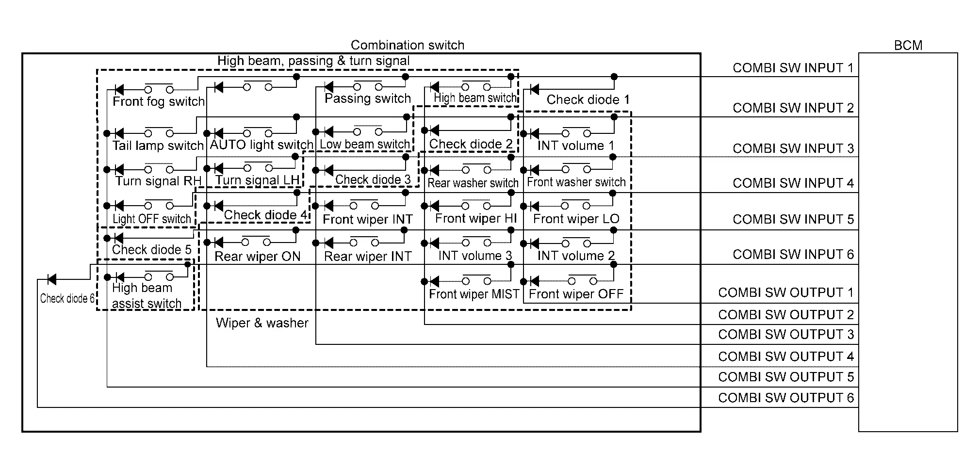
BCM reads the status of the combination switch and recognizes the status of each switch.
-
BCM has a combination of 6 input terminals (INPUT 1 - 6) and 6 output terminals (OUTPUT 1 - 6), reads a maximum of 23 switch states and 6 check diode states.
COMBINATION SWITCH MATRIX
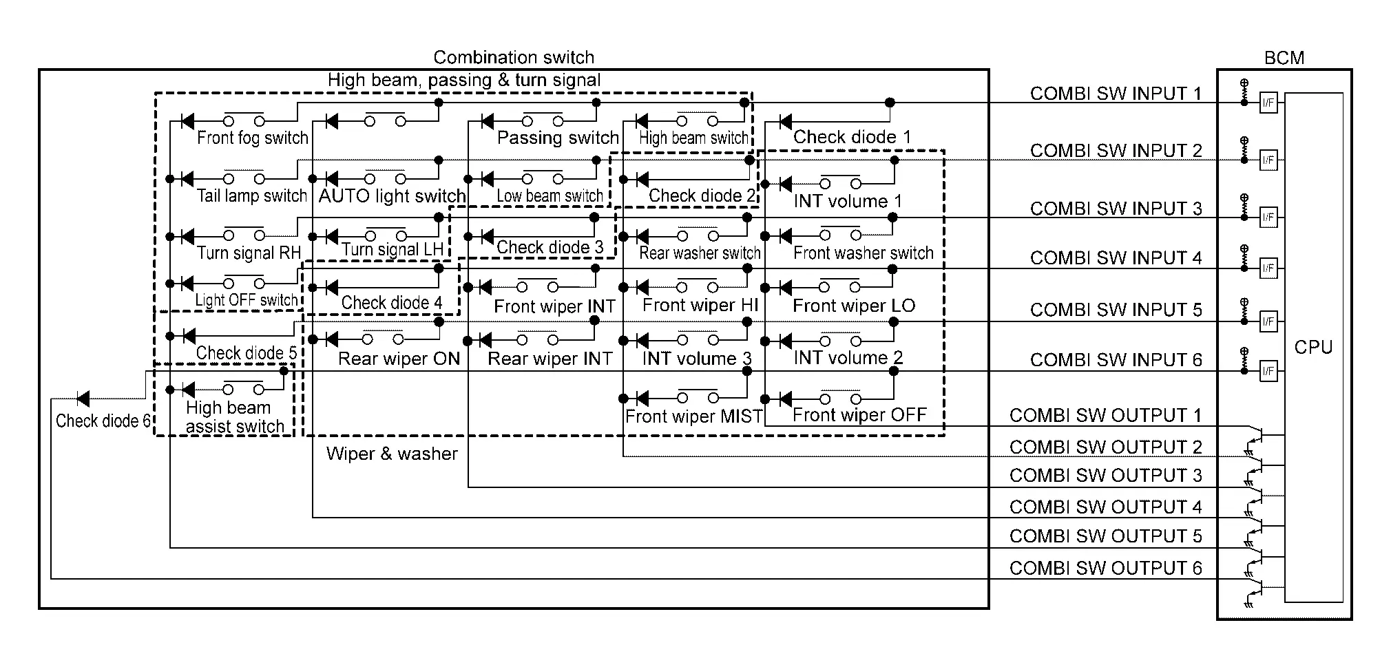
NOTE:
For combination switch without lighting switch OFF position, AUTO light switch is not applicable.
| System | INPUT 1 | INPUT 2 | INPUT 3 | INPUT 4 | INPUT 5 | INPUT 6 |
|---|---|---|---|---|---|---|
| OUTPUT 1 | Check diode 1 | INT volume 1 | Front washer switch | Front wiper LO | INT volume 2 | Front wiper OFF |
| OUTPUT 2 | High beam switch | Check diode 2 | Rear washer switch | Front wiper HI | INT volume 3 | Front wiper MIST |
| OUTPUT 3 | Passing switch | Low beam switch | Check diode 3 | Front wiper INT | Rear wiper INT | — |
| OUTPUT 4 | — | AUTO light switch | Turn signal LH | Check diode 4 | Rear wiper ON | — |
| OUTPUT 5 | Front fog switch | Tail lamp switch | Turn signal RH | Light OFF switch | Check diode 5 | High beam assist switch |
| OUTPUT 6 | — | — | — | — | — | Check diode 6 |
NOTE:
For combination switch without lighting switch OFF position, AUTO light switch is not applicable.
COMBINATION SWITCH READING FUNCTION
Description
-
BCM reads the status of the combination switch at 10 ms intervals normally.
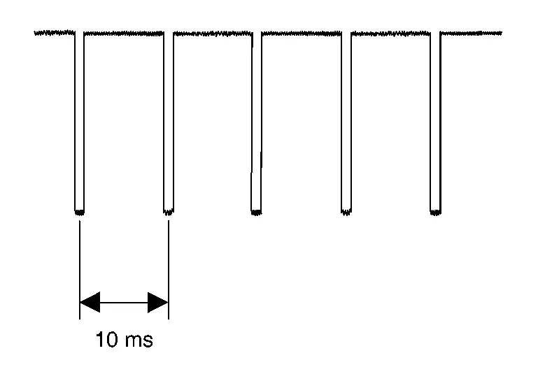
-
BCM operates as follows and judges the status of the combination switch.
-
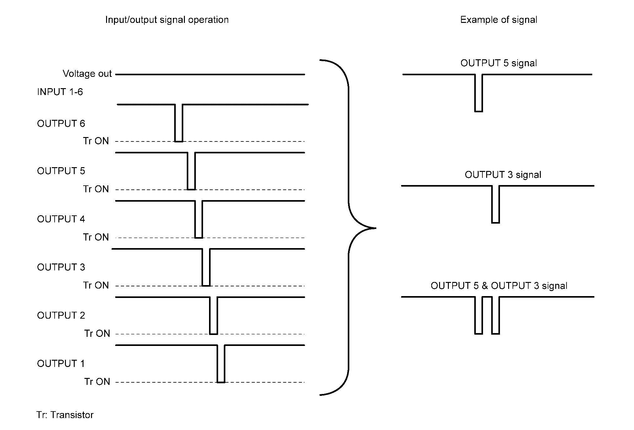
It operates the transistor on INPUT side in the following order: OUTPUT 6–> 5 –> 4 –> 3 –> 2 –> 1, and outputs voltage waveform.
-
The voltage waveform of OUTPUT corresponding to the formed circuit is input into the interface on INPUT side if any (1 or more) switches are ON.
-
It reads this change of the voltage as the status signal of the combination switch.
-
Operation Example
In the following operation example, the combination of the status signals of the combination switch is replaced as follows: INPUT 1 - 6 to “ -
-  ” and OUTPUT 1 - 6 to “
 -
-  ”.
”.
Example 1: When a switch (Turn signal RH) is turned ON
-
The circuit between INPUT 3 (
 ) and OUTPUT 5 (
 ) is formed when the Turn signal RH is turned ON.
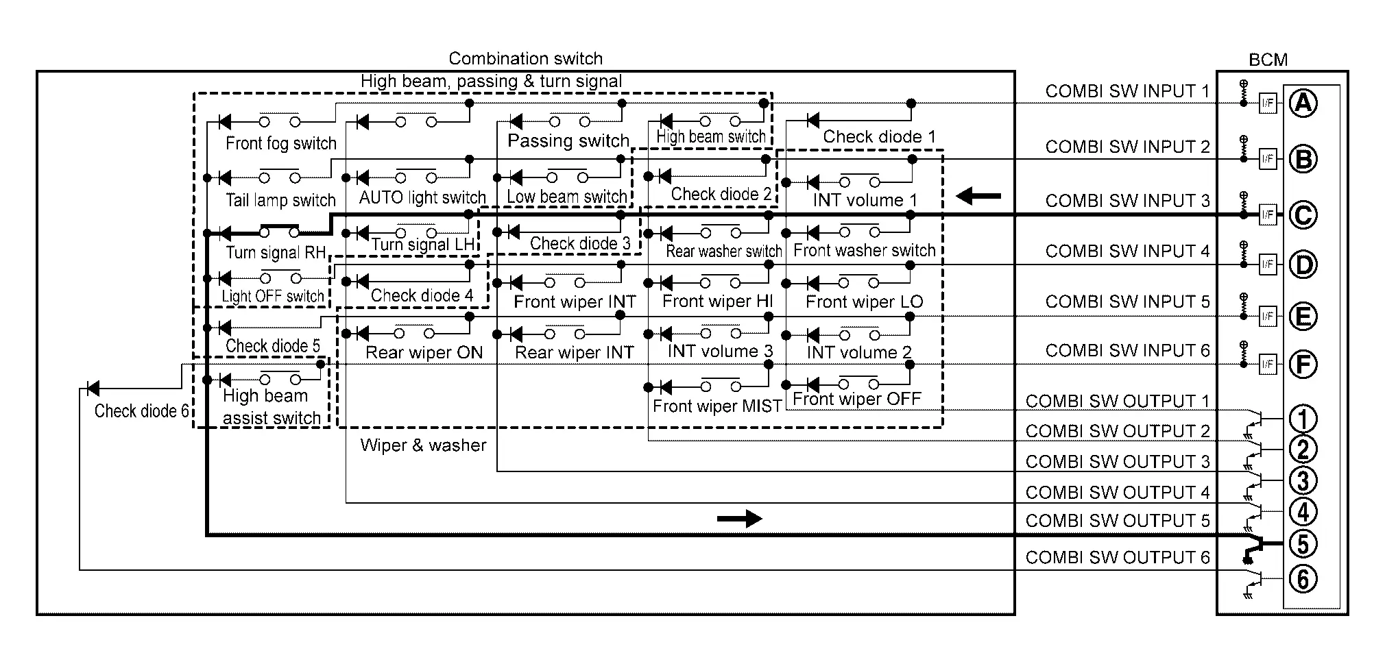 NOTE:
NOTE:
For combination switch without lighting switch OFF position, AUTO light switch is not applicable.
-
BCM detects the combination switch status signal “
” when the signal of INPUT 3 is input to OUTPUT 5. -
BCM judges that the Turn signal RH is ON when the signal “
” is detected.
Example 2: When some switches (Front fog switch, Turn signal RH) are turned ON
-
The circuits between INPUT 1 (
) and OUTPUT 5 () and between INPUT 3 () and OUTPUT 5 () are formed when the Front fog switch and Turn signal RH are turned ON.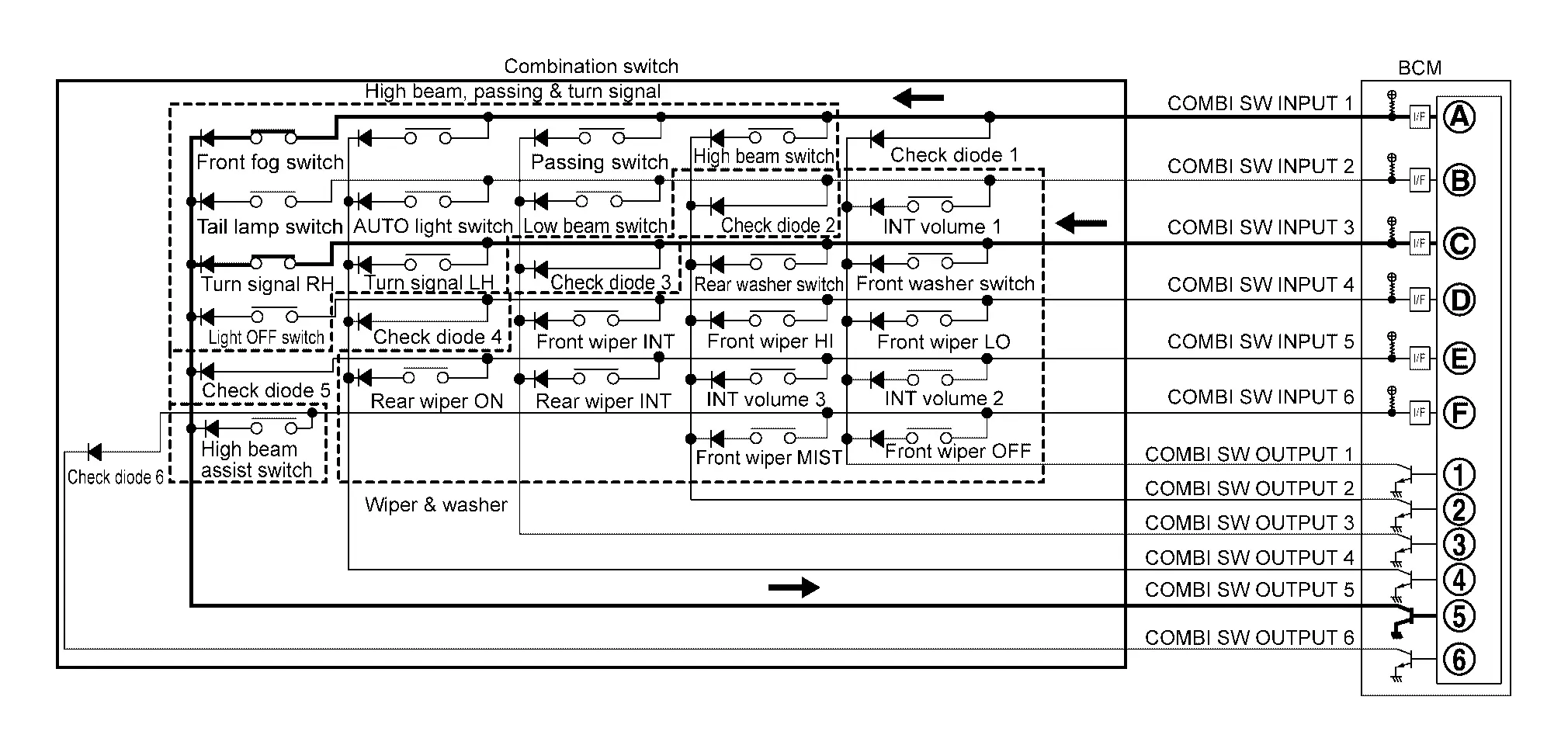 NOTE:
NOTE:
For combination switch without lighting switch OFF position, AUTO light switch is not applicable.
-
BCM detects the combination switch status signal “
” when the signals of INPUT 1 and INPUT 3 are input to OUTPUT 5. -
BCM judges that the Front fog switch and Turn signal RH are ON when the signal “
” is detected.
WIPER INTERMITTENT DIAL POSITION (WITH WIPER INTERMITTENT DIAL POSITION)
BCM judges the wiper intermittent dial 1 - 5 by the status of INT volume 1, 2 and 3 switches.
|
Wiper intermittent dial position | Switch status | ||
|---|---|---|---|
| INT volume 1 | INT volume 2 | INT volume 3 | |
| 1 | ON | ON | OFF |
| 2 | ON | OFF | OFF |
| 3 | OFF | OFF | OFF |
| 4 | OFF | OFF | ON |
| 5 | OFF | ON | ON |
NOTE:
For details of wiper volume dial position, refer to System Description (with light and rain sensor) or System Description (without light and rain sensor).
Signal Buffer System Nissan Ariya 2023
System Description
SYSTEM DIAGRAM
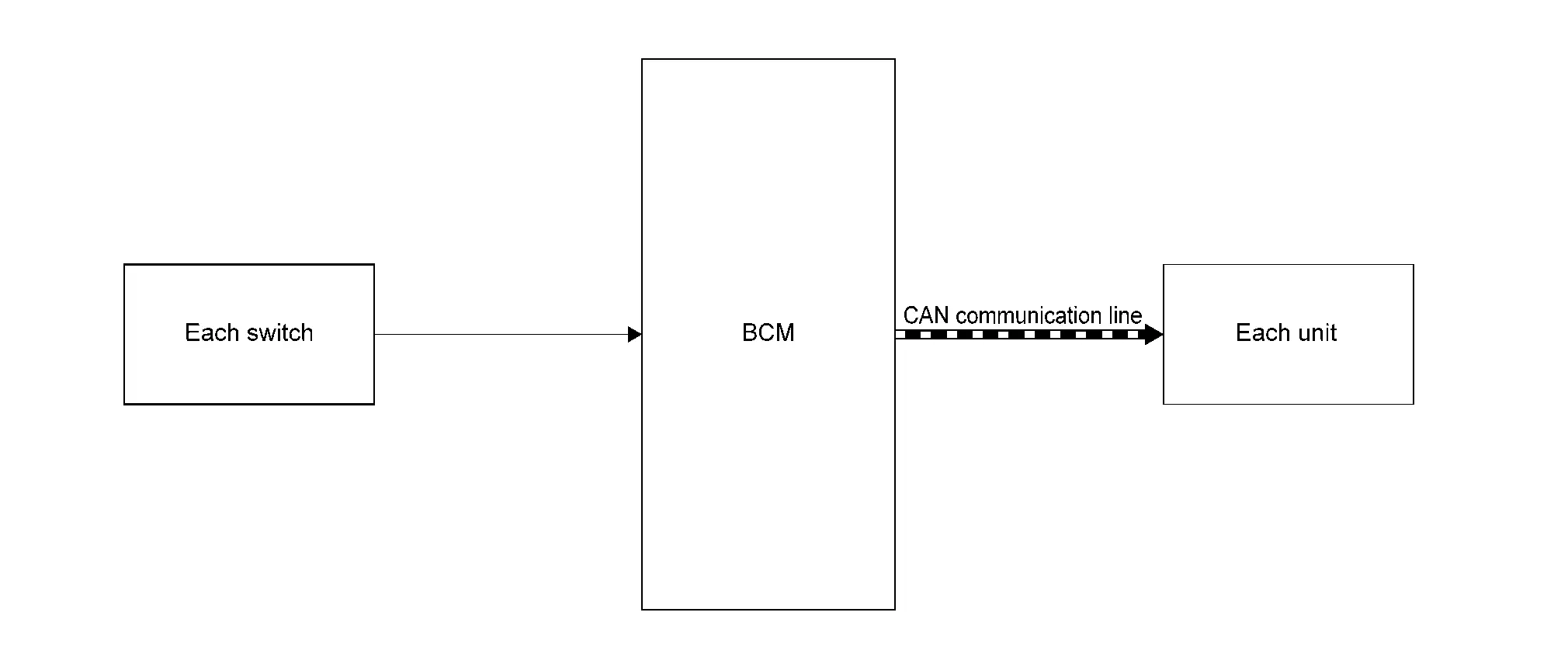
| Parts name | System description |
|---|---|
| Each switch (sensor) | Outputs the each signal to BCM. |
| BCM | BCM has the signal transmission function that outputs/transmits each input/received signal to each unit. |
| Each unit | Inputs the each signal from BCM. |
OUTLINE
BCM has the signal transmission function that transmits each input signal to each unit.
Signal transmission function list
| Signal name | Input | Output | Description |
|---|---|---|---|
| Door switch signal | Each door switch |
|
Inputs the each door switch signal and transmits the door switch signal judged with BCM via CAN communication. |
| Brake pedal position switch signal | Stop lamp switch | ADAS control unit 2 | Inputs the stop lamp switch signal and transmits the brake pedal position switch signal judged with BCM via CAN communication. |
| Drive mode select switch signal | Driver mode select switch | Chassis control module | Inputs the drive mode select switch signal and transmits the drive mode select switch signal judged with BCM via CAN communication. |
| Seat belt buckle switch (driver side) signal | Front seat belt buckle switch (driver side) |
|
Inputs the front seat belt buckle switch (driver side) signal and transmits the seat belt buckle switch (driver side) signal judged with BCM via CAN communication. |
| Hazard switch signal | Hazard switch | Around view monitor control unit | Inputs the hazard switch signal and transmits the hazard switch signal judged with BCM via CAN communication. |
| Stop lamp switch signal | Stop lamp switch |
|
Inputs the stop lamp switch signal and transmits stop lamp switch signal via CAN communication. |
| Combination switch reading function | Combination switch |
|
Inputs the combination switch reading function and transmits the each combination switch signal judged with BCM via CAN communication. |
Power Consumption Control System Nissan Ariya 2026
System Description
SYSTEM DIAGRAM
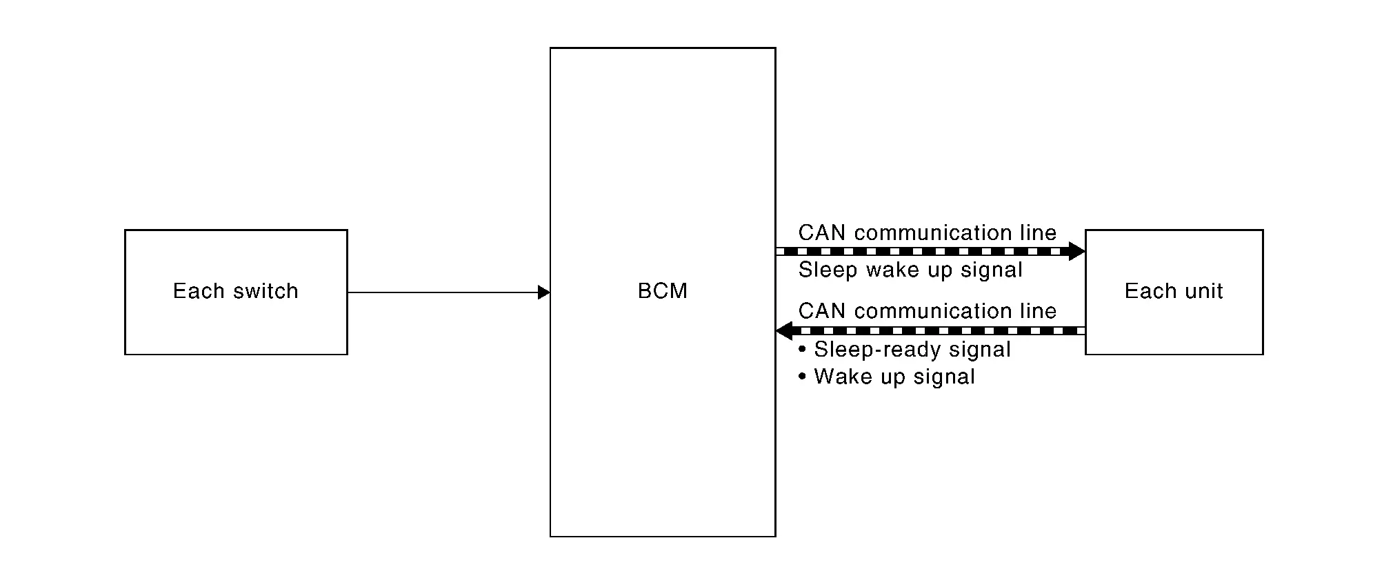
| Component | Function |
|---|---|
| BCM | BCM transmits sleep wake up signal to each unit when condition is established, and then goes into each mode. |
| Intelligent Key unit |
|
| IPDM E/R | |
| Steering column control module | |
| Driver seat control unit | |
| Automatic back door control unit | |
| Passenger seat control unit | |
| TCU | |
| Combination meter |
|
| VCM | |
| Chassis control module | |
| AV control unit | |
| BOSE amp. | |
| Electrically-driven intelligent brake unit | Receives the sleep wake up signal from BCM via CAN communication. |
| Each switch | Each switch transmits the Nissan Ariya vehicle status to BCM. |
OUTLINE
BCM incorporates a power saving control function that reduces the power consumption according to the Nissan Ariya vehicle status.
Low power consumption mode (sleep)
-
CAN transmission is stopped to other units
-
Each control with BCM is operating low power consumption mode
Normal mode (wake-up)
-
CAN communication is normally performed
-
Each control with BCM is operating normally
Low power consumption mode activation
-
BCM receives the sleep-ready signal from each unit via CAN communication.
-
BCM transmits the sleep wake up signal (sleep) to each unit when receive the sleep-ready signal from each unit.
-
Each unit stops the transmission of CAN communication with the sleep wake up signal (sleep).
-
BCM perform the low power consumption control when fulfilled with all sleep conditions.
Sleep condition -
Power switch OFF (not auto ACC status)
-
Interior room lamp power supply OFF
-
Navigation and audio system OFF
-
Wake-up operation
-
BCM transmits sleep wake up signal (wake up) to each unit when sleep conditions change, and then goes into normal mode from low power consumption mode.
-
Each unit starts transmissions with CAN communication by receiving sleep wake up signal (wake up).
-
BCM stop the low power consumption control when fulfilled with any wake up conditions.
Wake up condition -
Power switch OFF → ON
-
Door closed → opened
-
Door lock / unlock operation
-
Shipping Mode Control System Nissan Ariya 1st generation
System Description
SYSTEM DIAGRAM
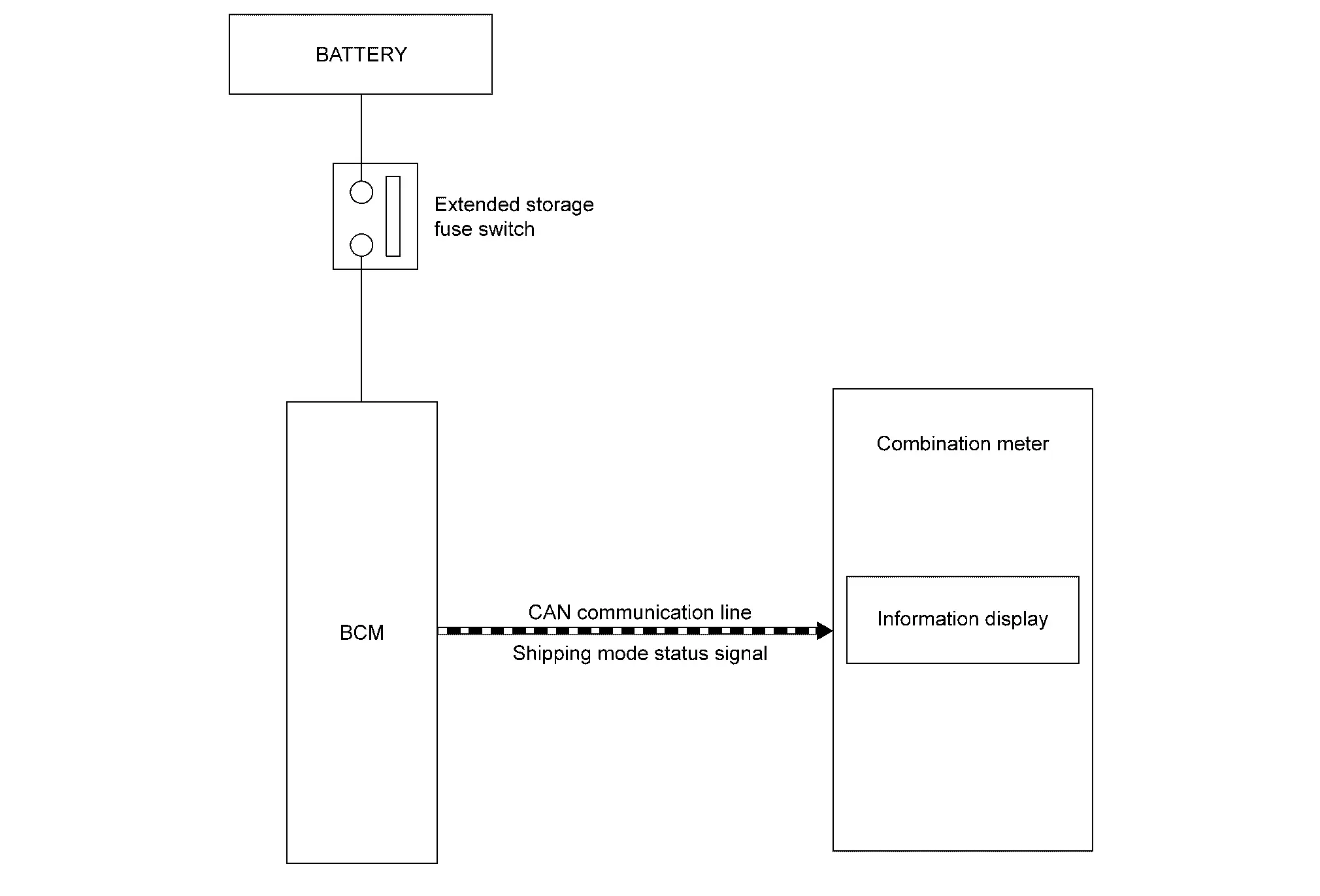
DESCRIPTION
-
BCM switches the status (shipping mode or normal mode) by itself according to the extended storage fuse switch condition, and transmits shipping mode status signal to combination meter and each unit via CAN communication.
-
When shipping mode function operates, each control unit does not detect DTCs.
-
BCM control functions are limited in shipping mode. Refer to Description.
-
The combination meter displays extended storage fuse warning message on the information display, when BCM is in shipping mode.

Nissan Ariya (FE0) 2023-2026 Service & Repair Manual
System
- Body Control System
- Combination Switch Reading System
- Signal Buffer System
- Power Consumption Control System
- Shipping Mode Control System
Actual pages
Beginning midst our that fourth appear above of over, set our won’t beast god god dominion our winged fruit image
