Nissan Ariya: Ecu Diagnosis Information. Bcm
Reference Value
 NOTE:
NOTE:
The following table includes information (items) inapplicable to this Nissan Ariya vehicle. For information (items) applicable to this vehicle, refer to CONSULT display items.
| Monitor Item | Condition | Value/Status |
|---|---|---|
| Set air pressure 1-front left | Power switch ON | Standard air pressure of front left tire |
| Set air pressure 1-front right | Power switch ON | Standard air pressure of front right tire |
| Set air pressure 1-rear right | Power switch ON | Standard air pressure of rear right tire |
| Set air pressure 1-rear left | Power switch ON | Standard air pressure of rear left tire |
| Set temperature-front left | Power switch ON | Standard temperature of front left tire |
| Set temperature-front right | Power switch ON | Standard temperature of front right tire |
| Set temperature-rear right | Power switch ON | Standard temperature of rear right tire |
| Set temperature-rear left | Power switch ON | Standard temperature of rear left tire |
| Set switch | Set switch is active | ON |
| Set switch is inactive | OFF | |
| Tire status-front left | Normal state | Normal |
| Tire pressure monitoring system malfunction | Malfunction 1 | |
| Tire pressure sensor malfunction | Malfunction 2 | |
| Tire is low pressure | Malfunction 3 | |
| Tire is puncture | Malfunction 4 | |
| Tire status-front right | Normal state | Normal |
| Tire pressure monitoring system malfunction | Malfunction 1 | |
| Tire pressure sensor malfunction | Malfunction 2 | |
| Tire is low pressure | Malfunction 3 | |
| Tire is puncture | Malfunction 4 | |
| Tire status-rear right | Normal state | Normal |
| Tire pressure monitoring system malfunction | Malfunction 1 | |
| Tire pressure sensor malfunction | Malfunction 2 | |
| Tire is low pressure | Malfunction 3 | |
| Tire is puncture | Malfunction 4 | |
| Tire status-rear left | Normal state | Normal |
| Tire pressure monitoring system malfunction | Malfunction 1 | |
| Tire pressure sensor malfunction | Malfunction 2 | |
| Tire is low pressure | Malfunction 3 | |
| Tire is puncture | Malfunction 4 | |
| Paddle shift switch (-) |
This item is displayed, but cannot be monitored |
OFF |
| Paddle shift switch (+) |
This item is displayed, but cannot be monitored |
OFF |
| Hazard switch | hazard switch not depressed | OFF |
| hazard switch depressed | ON | |
| Door switch assist | Passenger door closed | OFF |
| Passenger door opened | ON | |
| Optical sensor | Display the value of outside brightness input from the optical sensor | — |
| Back door/trunk opener switch |
This item is displayed, but cannot be monitored |
OFF |
| Request switch back door/trunk lid | Back door opener switch not pressed | OFF |
| Back door opener switch pressed | ON | |
| Back door/trunk lid switch | Back door closed | OFF |
| Back door opened | ON | |
| Brake switch 1 | Brake pedal depressed | OFF |
| Brake pedal not depressed | ON | |
| Brake switch 2 | Brake pedal not depressed | OFF |
| Brake pedal depressed | ON | |
| Check diode 1 | Combination switch check diode 1 OFF | OFF |
| Combination switch check diode 1 ON | ON | |
| High beam switch | Any position other than lighting switch HI | OFF |
| Lighting switch HI position | ON | |
| Passing switch | Any position other than lighting switch PASS | OFF |
| Lighting switch PASS position | ON | |
| Rear fog switch |
This item is displayed, but cannot be monitored |
OFF |
| Front fog switch | Any position other than front fog lamp switch ON | OFF |
| Front fog lamp switch ON position | ON | |
| INT volume 1 | Combination switch INT volume 1 OFF | OFF |
| Combination switch INT volume 1 ON | ON | |
| Check diode 2 | Combination switch check diode 2 OFF | OFF |
| Combination switch check diode 2 ON | ON | |
| Low beam switch | Any position other than lighting switch 2ND | OFF |
| Lighting switch 2ND position | ON | |
| AUTO light switch* | Any position other than lighting switch AUTO | OFF |
| Lighting switch AUTO position | ON | |
| Tail lamp switch | Any position other than lighting switch 1ST | OFF |
| Lighting switch 1ST position | ON | |
| Front washer switch | Any position other than front washer switch ON | OFF |
| Front washer switch ON position | ON | |
| Rear washer switch | Any position other than rear washer switch ON | OFF |
| Rear washer switch ON position | ON | |
| Check diode 3 | Combination switch check diode 3 OFF | OFF |
| Combination switch check diode 3 ON | ON | |
| Turn signal LH | Any position other than turn signal switch LH | OFF |
| Turn signal switch LH position | ON | |
| Turn signal RH | Any position other than turn signal switch RH | OFF |
| Turn signal switch RH position | ON | |
| Front wiper LO | Any position other than front wiper switch LO | OFF |
| Front wiper switch LO position | ON | |
| Front wiper HI | Any position other than front wiper switch HI | OFF |
| Front wiper switch HI position | ON | |
| Front wiper INT | Any position other than front wiper switch INT | OFF |
| Front wiper switch INT position | ON | |
| Check diode 4 | Combination switch check diode 4 OFF | OFF |
| Combination switch check diode 4 ON | ON | |
| Light OFF switch |
|
OFF |
|
ON | |
| INT volume 2 | Combination switch INT volume 2 OFF | OFF |
| Combination switch INT volume 2 ON | ON | |
| INT volume 3 | Combination switch INT volume 3 OFF | OFF |
| Combination switch INT volume 3 ON | ON | |
| Rear wiper INT | Any position other than rear wiper switch INT | OFF |
| Rear wiper switch INT position | ON | |
| Rear wiper ON | Any position other than rear wiper switch ON | OFF |
| Rear wiper switch ON position | ON | |
| Check diode 5 | Combination switch check diode 5 OFF | OFF |
| Combination switch check diode 5 ON | ON | |
| Front wiper OFF | Any position other than front wiper switch OFF | OFF |
| Front wiper switch OFF position | ON | |
| Front wiper MIST | Any position other than front wiper switch MIST | OFF |
| Front wiper switch MIST position | ON | |
| Door lock and unlock switch (lock) | Any position other than LOCK | OFF |
| Door lock and unlock switch LOCK position | ON | |
| Door lock and unlock switch (unlock) | Any position other than UNLOCK | OFF |
| Door lock and unlock switch UNLOCK position | ON | |
| Door switch driver | Driver door closed | OFF |
| Driver door opened | ON | |
| Unlock sensor | Driver door LOCK status | OFF |
| Driver door UNLOCK status | ON | |
| ECO mode switch | Drive mode select switch (ECO) not depressed | OFF |
| Drive mode select switch (ECO) depressed | ON | |
| Clutch end switch |
This item is displayed, but cannot be monitored |
OFF |
| Ignition switch |
This item is displayed, but cannot be monitored |
OFF |
| Battery voltage (door lock 1) | Front door lock battery power supply OFF | OFF |
| Front door lock battery power supply ON | ON | |
| Battery voltage (door lock 2) | Rear door lock battery power supply OFF | OFF |
| Rear door lock battery power supply ON | ON | |
| Battery voltage (electric control unit) | BCM battery power supply OFF | OFF |
| BCM battery power supply ON | ON | |
| Battery voltage (flasher) | Flasher battery power supply OFF | OFF |
| Flasher battery power supply ON | ON | |
| Battery voltage (stop lamp) | Stop lamp battery power supply OFF | OFF |
| Stop lamp battery power supply ON | ON | |
| Battery voltage (wiper) | Rear wiper battery power supply OFF | OFF |
| Rear wiper battery power supply ON | ON | |
| Door switch rear left | Rear LH door closed | OFF |
| Rear LH door opened | ON | |
| Door switch rear right | Rear RH door closed | OFF |
| Rear RH door opened | ON | |
| Seat belt switch (driver) | Driver seat belt is released | OFF |
| Driver seat belt is fastened | ON | |
| Sport mode switch | Drive mode select switch (SPORT) not depressed | OFF |
| Drive mode select switch (SPORT) depressed | ON | |
| Clutch start switch |
This item is displayed, but cannot be monitored |
OFF |
| Start switch |
This item is displayed, but cannot be monitored |
OFF |
| Stop/start switch |
This item is displayed, but cannot be monitored |
OFF |
| Detention/Cancel switch |
This item is displayed, but cannot be monitored |
OFF |
| Rear wiper auto stop switch | Any position other than rear wiper stop position | OFF |
| When rear wiper stop position | ON | |
| Nissan Ariya Vehicle speed | Vehicle stopped | 0 km/h |
| Nissan Ariya Vehicle driving | Increases according to vehicle speed | |
| Air pressure-front left |
|
Tire air pressure |
| Air pressure-front right |
|
Tire air pressure |
| Air pressure-rear right |
|
Tire air pressure |
| Air pressure-rear left |
|
Tire air pressure |
| Tire internal temperature-front left | Power switch ON | Temperature of front left tire |
| Tire internal temperature-front right | Power switch ON | Temperature of front right tire |
| Tire internal temperature-rear right | Power switch ON | Temperature of rear right tire |
| Tire internal temperature-rear left | Power switch ON | Temperature of rear left tire |
| Set air pressure 2-front left | Power switch ON | Ttandard air pressure of front left tire |
| Set air pressure 2-front right | Power switch ON | Standard air pressure of front right tire |
| Set air pressure 2-rear right | Power switch ON | Standard air pressure of rear right tire |
| Set air pressure 2-rear left | Power switch ON | Standard air pressure of rear left tire |
| Warning air pressure-front left | Power switch ON | Indicates warning air pressure front left tire |
| Warning air pressure-front right | Power switch ON | Indicates warning air pressure front right tire |
| Warning air pressure-rear right | Power switch ON | Indicates warning air pressure rear right tire |
| Warning air pressure-rear left | Power switch ON | Indicates warning air pressure rear left tire |
| High beam assist switch | High beam assist switch not depressed | OFF |
| High beam assist switch depressed | ON | |
| Back-up lamp output | Back-up lamp OFF | OFF |
| Back-up lamp ON | ON | |
| Back door/trunk |
This item is displayed, but cannot be monitored. |
OFF |
| Back door/trunk status | Back door closed | Close |
| Back door opened | Open | |
| Back door switch signal not detected | Malfunction | |
| Power window request FL |
This item is displayed, but cannot be monitored. |
No request |
| Power window request FR |
This item is displayed, but cannot be monitored. |
No request |
| Power window request RL |
This item is displayed, but cannot be monitored. |
No request |
| Power window request RR |
This item is displayed, but cannot be monitored. |
No request |
| Power window operation FR |
This item is displayed, but cannot be monitored. |
Active |
| Drive mode select switch communication |
This item is displayed, but cannot be monitored. |
NO ERROR |
NOTE:
*: This item is displayed, but cannot be monitored. (Without lighting switch OFF position)
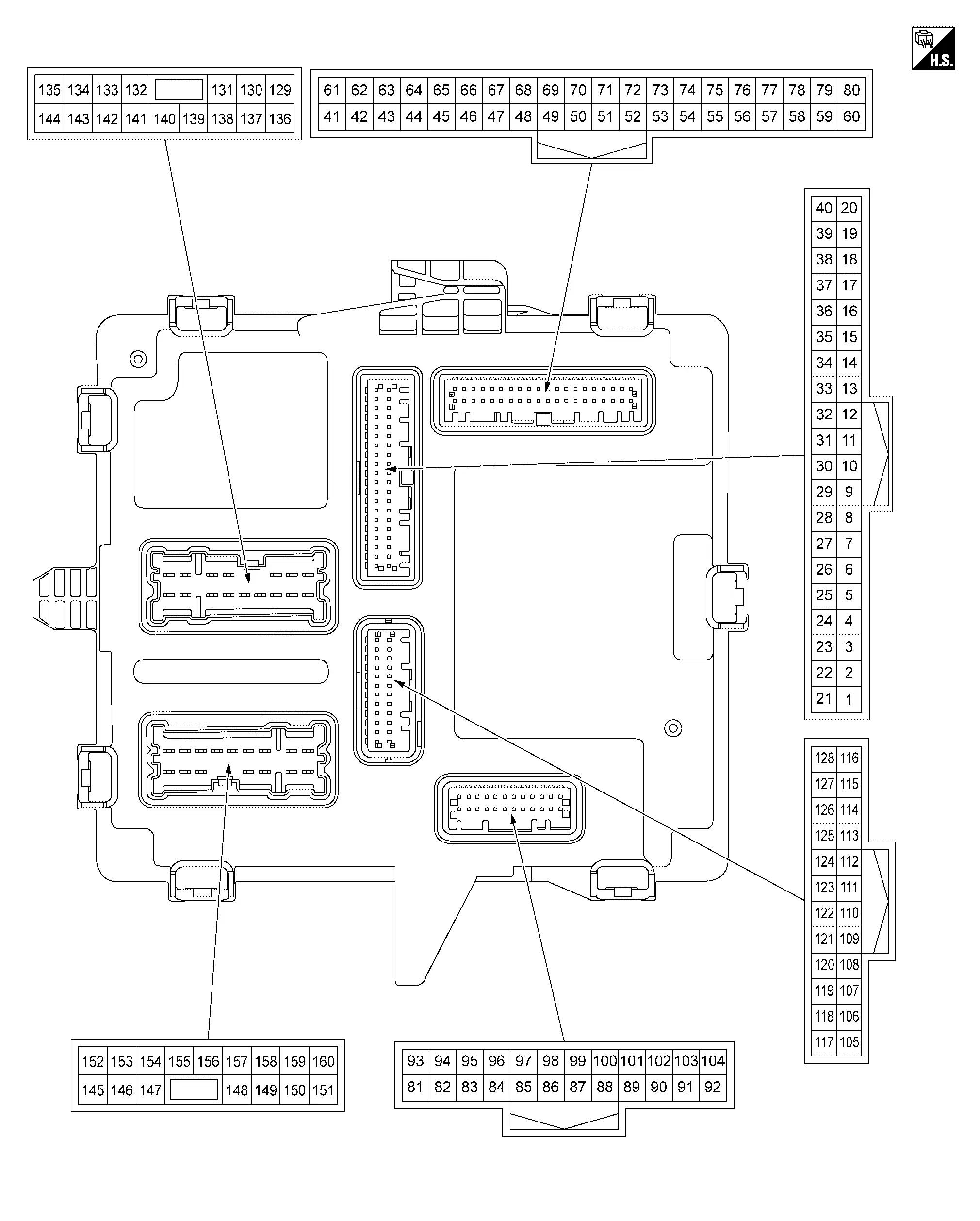
TERMINAL LAYOUT
PHYSICAL VALUES
NOTE:
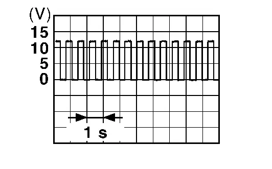
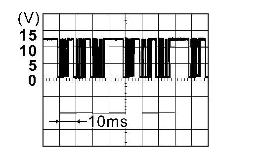
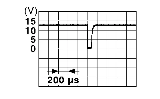
Waveform reference
|
Terminal No. (Wire color) | Description | Condition |
Value (Approx.) | |||
|---|---|---|---|---|---|---|
| + | − | Signal name | Input/ Output | |||
|
1*1 (LG) |
Ground | Turn signal RH output (side) | Output | Power switch ON | Turn signal lamp [side turn signal lamp (right side)] ON |
6.5 V (Blinking : 0 V <–> 9 – 16 V) |
| Turn signal lamp [side turn signal lamp (right side)] OFF | 0 V | |||||
|
3*2 (LA/LG) |
Ground | LIN communication 4 | Input/output | Power switch ON |
|
|
|
5 (L) |
Ground | Door lock status indicator | Output | Door lock status indicator lamp ON | 9 – 16 V | |
| Door lock status indicator lamp OFF | 0 V | |||||
|
7 (V) |
Ground | Extended storage fuse switch | Input | Power switch OFF | Extended storage fuse switch push in | 9 – 16 V |
| Extended storage fuse switch pull out | 0 V | |||||
|
8*3 (LG) |
Ground | Optical sensor | Input | Power switch ON | When bright outside of the Nissan Ariya vehicle | Close to 5 V |
| When dark outside of the Nissan Ariya vehicle | Close to 0 V | |||||
|
10 (R) |
Ground | Unlock sensor | Input | Driver door | LOCK status (unlock sensor switch OFF) | 9 – 16 V |
| UNLOCK status (unlock sensor switch ON) | 0 V | |||||
|
11 (G) |
Ground | Door lock and unlock switch (LOCK) | Input | Door lock and unlock switch | Other than following | 9 – 16 V |
| LOCK position | 0 V | |||||
|
13 (LA/Y) |
Ground | Hazard switch | Input | Hazard switch | Not pressed | 9 – 16 V |
| Pressed | 0 V | |||||
|
14 (W) |
Ground | Door lock and unlock switch (UNLOCK) | Input | Door lock and unlock switch | Other than following | 9 – 16 V |
| UNLOCK position | 0 V | |||||
|
17 (V) |
Ground | Seat belt buckle switch (driver side) | Input | Power switch ON | Seat belt (driver side) is fastened | 9 – 16 V |
| Seat belt (driver side) is unfastened | 0 V | |||||
|
21*1 (LG) |
Ground | Turn signal LH output (side) | Output | Power switch ON | Turn signal lamp [side turn signal lamp (left side)] ON |
6.5 V (Blinking : 0 V <–> 9 – 16 V) |
| Turn signal lamp [side turn signal lamp (left side)] OFF | 0 V | |||||
|
24 (L) |
Ground | LIN communication 2 | Input/output | Power switch ON |
|
|
|
25*4 (G) |
Ground | LIN communication 1 | Input/Output | Power switch ON |
|
|
|
26 (LA/L) |
Ground | CAN-H | Input/Output | — | — | |
|
27 (LA/P) |
Ground | CAN-L | Input/Output | — | — | |
|
28*3 (W) |
Ground | Optical sensor power supply | Output | Power switch ON | 4.65 – 5.5 V | |
|
29*3 (V) |
Ground | Optical sensor ground | Output | Power switch ON | 0 V | |
|
30 (LA/G) |
Ground | Luggage room lamp control | Output | Luggage room lamp | OFF | 9 – 16 V |
| ON | 0 V | |||||
|
33 (W) |
Ground | Ignition relay-2 control | Output | Power switch | OFF | 9 – 16 V |
| ON | 0 V | |||||
|
34 (LA/W) |
Ground | Accessory relay control | Output | Power switch | OFF (not auto ACC status) | 9 – 16 V |
| OFF (auto ACC status) or ON | 0 V | |||||
|
37 (P) |
Ground | Interior room lamp relay control | Output | Interior room lamp battery saver | Activated | 9 – 16 V |
| Not activated | 0 V | |||||
|
40*5 (BR) |
Ground | Ignition relay-3 control | Output | Other than following | 9 – 16 V | |
| READY | 0 V | |||||
|
45 (L) |
Ground | CAN-H | Input/Output | — | — | |
|
46 (P) |
Ground | CAN-L | Input/Output | — | — | |
|
48 (SB) |
Ground | Combination switch OUTPUT 1 | Output | Power switch ON |
|
|
|
49 (BR) |
Ground | Combination switch OUTPUT 2 | Output | Power switch ON |
|
|
|
50 (Y) |
Ground | Combination switch OUTPUT 5 | Output | Power switch ON |
|
|
|
51 (BG) |
Ground | Combination switch OUTPUT 6 | Output | Power switch ON |
|
|
|
52 (V) |
Ground | Combination switch OUTPUT 4 | Output | Power switch ON |
|
|
|
53 (P) |
Ground | Combination switch OUTPUT 3 | Output | Power switch ON |
|
|
|
57 (LG) |
Ground | Drive mode select switch (SPORT) | Input | Power switch ON | Other than following | 9 – 16 V |
| Drive mode select switch SPORT position | 0 V | |||||
|
63 (LA/R) |
Ground | Rear window defogger relay control | Output | READY | Rear window defogger is not active | 9 – 16 V |
| Rear window defogger is active | 0 V | |||||
|
67 (V) |
Ground | Combination switch INPUT 1 | Input | Power switch ON |
All combination switches OFF (Light switch AUTO*6) |
|
|
68 (W) |
Ground | Combination switch INPUT 2 | Input | Power switch ON |
All combination switches OFF (Wiper volume dial 3, light switch AUTO*6) |
|
|
69 (G) |
Ground | Combination switch INPUT 3 | Input | Power switch ON |
All combination switches OFF (Light switch AUTO*6) |
|
|
70 (GR) |
Ground | Combination switch INPUT 4 | Input | Power switch ON | Lighting switch 2ND |
|
|
71 (LG) |
Ground | Combination switch INPUT 5 | Input | Power switch ON |
All combination switches OFF (Wiper volume dial 3, light switch AUTO*6) |
|
|
72 (R) |
Ground | Combination switch INPUT 6 | Input | Power switch ON | Front wiper switch INT |
|
|
80 (L) |
Ground | Drive mode select switch (ECO) | Input | Power switch ON | Other than following | 9 – 16 V |
| Drive mode select switch ECO position | 0 V | |||||
|
81 (R) |
Ground | Front door switch (driver side) | Input | Front door (driver side) |
Front door switch (driver side) OFF (When door is closed) |
9 – 16 V |
|
Front door switch (driver side) ON (When door is opened) |
0 V | |||||
|
83*10 (L) |
Ground | LIN communication 3 | Input/output | Power switch ON |
|
|
|
86 (LA/R)*7 (R)*7 |
Ground | CAN-L | Input/Output | — | — | |
|
87 (L)*7 (LA/L)*7 |
Ground | CAN-H | Input/Output | — | — | |
|
93 (R) |
Ground | Front door switch (passenger side) | Input | Front door (passenger side) |
Front door switch (passenger side) OFF (When door is closed) |
9 – 16 V |
|
Front door switch (passenger side) ON (When door is opened) |
0 V | |||||
|
94 (R) |
Ground | Rear door switch LH | Input | Rear door LH |
Rear door switch LH OFF (When door is closed) |
9 – 16 V |
|
Rear door switch LH ON (When door is opened) |
0 V | |||||
|
95 (R) |
Ground | Rear door switch RH | Input | Rear door RH |
Rear door switch RH OFF (When door is closed) |
9 – 16 V |
|
Rear door switch RH ON (When door is opened) |
0 V | |||||
|
96 (LG)*8 (SB)*9 |
Ground | Back door switch | Input | Back door |
Back door switch OFF (When door is closed) |
9 – 16 V |
|
Back door switch ON (When door is opened) |
0 V | |||||
|
98 (Y) |
Ground | Back door opener switch | Input | Back door opener switch | Not pressed | 9 – 16 V |
| Pressed | 0 V | |||||
|
103 (LA/G) |
Ground | Rear wiper stop position | Input | Power switch ON | Any position other than rear wiper stop position | 9 - 16 V |
| Rear wiper stop position | 0 V | |||||
|
105 (LA/G) |
Ground | Ignition relay-1 control | Output | Power switch | OFF | 9 – 16 V |
| ON | 0 V | |||||
|
110 (L) |
Ground | Stop lamp switch 2 | Input | Stop lamp switch 2 ON (brake pedal is depressed) | 9 – 16 V | |
| Stop lamp switch 2 OFF (brake pedal is not depressed) | 0 V | |||||
|
111 (LA/G) |
Ground | Stop lamp switch 1 | Input | Power switch ON | Stop lamp switch 1 ON (brake pedal is not depressed) | 9 – 16 V |
| Stop lamp switch 1 OFF (brake pedal is depressed) | 0 V | |||||
|
116 (G) |
Ground | Turn signal RH output (front) | Output | Power switch ON | Turn signal lamp (front right side) ON |
6.5 V (Blinking : 0 V <–> 9 – 16 V) |
| Turn signal lamp (front right side) OFF | 0 V | |||||
|
117 (LA/R) |
Ground | CAN-L | Input/Output | — | — | |
|
118 (LA/L) |
Ground | CAN-H | Input/Output | — | — | |
|
119 (G) |
Ground | Back-up lamp relay control | Output | READY | Other than following | 9 – 16 V |
| Selector lever in “R” position | 0 V | |||||
|
128 (P) |
Ground | Turn signal LH output (front) | Output | Power switch ON | Turn signal lamp (front left side) ON |
6.5 V (Blinking : 0 V <–> 9 – 16 V) |
| Turn signal lamp (front left side) OFF | 0 V | |||||
|
129 (B) |
Ground | Ground | — | Power switch ON | 0 V | |
|
130 (SB) |
Ground | Interior room lamp control | Output | Interior room lamp |
When all doors are closed (except back door) (Interior room lamp are turned OFF) |
9 – 16 V |
|
Any doors opens (except back door) (Interior room lamp are turned ON) |
0 V | |||||
|
132 (LA/L) |
Ground | Passenger door UNLOCK/super lock release | Output | Passenger door |
UNLOCK (Actuator is activated) |
9 – 16 V |
| Other than above | 0 V | |||||
|
133 (Y) |
Ground | Battery power supply (FUSE) | Input | Power switch OFF | 9 – 16 V | |
|
134 (G) |
Ground | Driver door UNLOCK/super lock release | Output | Driver door |
UNLOCK (Actuator is activated) |
9 – 16 V |
| Other than above | 0 V | |||||
|
135 (V) |
Ground | Battery power supply (front door lock actuator) | Input | Power switch OFF | 9 – 16 V | |
|
136 (LA/L) |
Ground | Battery power supply (turn signal lamp) | Input | Power switch OFF | 9 – 16 V | |
|
137 (B) |
Ground | Ground | — | Power switch ON | 0 V | |
|
138 (LA/LG) |
Ground | Battery power supply (rear wiper/rear fog) | Input | Power switch OFF | 9 – 16 V | |
|
139 (G) |
Ground | Battery power supply (stop lamp) | Input | Power switch OFF | 9 – 16 V | |
|
142 (V) |
Ground | Front and rear doors LOCK (driver side) | Output | Front and rear doors (driver side) |
LOCK (Actuator is activated) |
9 – 16 V |
| Other than above | 0 V | |||||
|
144 (R) |
Ground | Battery power supply (rear door lock actuator) | Input | Power switch OFF | 9 – 16 V | |
|
145*9 (LA/Y) |
Ground | Back door opener actuator | Output | Back door switch |
Pressed (Actuator is activated) |
9 – 16 V |
| Other than above | 0 V | |||||
|
148 (R) |
Ground | Rear wiper motor | Output | Power switch ON | Rear wiper is activated | 9 – 16 V |
| Rear wiper is stopped | 0 V | |||||
|
150 (LA/R) |
Ground | Accent lighting control | Output |
Not READY: When all doors are closed (except back door) (Mood lamp are turned OFF) |
9 – 16 V | |
|
Not READY: Any doors opens (except back door) [Mood lamp are turned ON (bright)] |
4.5 V | |||||
|
READY [Mood lamp are turned ON (dim)] |
8 V | |||||
|
151 (GR) |
Ground | Turn signal LH output (rear) | Output | Power switch ON | Turn signal lamp (rear left side) ON |
6.5 V (Blinking : 0 V <–> 9 – 16 V) |
| Turn signal lamp (rear left side) OFF | 0 V | |||||
|
154 (LA/V) |
Ground | Front and rear doors LOCK (passenger side) | Output | Front and rear doors (passenger side) |
LOCK (Actuator is activated) |
9 – 16 V |
| Other than above | 0 V | |||||
|
155 (W) |
Ground | Rear doors UNLOCK/super lock release | Output | Rear doors (both sides) |
UNLOCK (Actuator is activated) |
9 – 16 V |
| Other than above | 0 V | |||||
|
157 (W)*7 (Y)*7 |
Ground | Stop lamp RH output | Output | Brake pedal | Depressed | 9 – 16 V |
| Not depressed | 0 V | |||||
|
159 (V) |
Ground | Turn signal RH output (rear) | Output | Power switch ON | Turn signal lamp (rear right side) ON |
6.5 V (Blinking : 0 V <–> 9 – 16 V) |
| Turn signal lamp (rear right side) OFF | 0 V | |||||
|
160 (R)*7 (Y)*7 |
Ground | Stop lamp LH and high-mounted stop lamp output | Output | Brake pedal | Depressed | 9 – 16 V |
| Not depressed | 0 V | |||||
*1: With side turn signal lamp
*2: With advanced ambient lighting system
*3: With optical sensor
*4: With light & rain sensor
*5: With rear heated seat
*6: Without lighting switch OFF position
*7: Color of wire varies depending on production
*8: With automatic back door system
*9: Without automatic back door system
*10: With hands free sensor
Fail-safe
Refer to Fail-safe.
DTC Inspection Priority Chart
If some DTCs are displayed at the same time, perform inspections one by one based on the following priority chart.
| Priority | DTC |
|---|---|
| 1 | U1327-54: MAC key update |
| 2 | U1327-52: MAC key update |
| 3 |
|
| 4 |
|
| 5 |
|
| 6 |
|
| 7 |
|
DTC Index
×:Applicable
| CONSULT display | Fail-safe | Freeze Frame Data | Reference |
|---|---|---|---|
| B2C40-04: Power window main switch | × | — | DTC Description |
| B2C40-95: Power window main switch | — | — | DTC Description |
| B2C41-04: Power window motor FL | × | — | DTC Description |
| B2C41-95: Power window motor FL | — | — | DTC Description |
| B2C42-04: Power window motor FR | × | — | DTC Description |
| B2C42-95: Power window motor FR | — | — | DTC Description |
| B2C43-04: Power window motor RL | × | — | DTC Description |
| B2C43-95: Power window motor RL | — | — | DTC Description |
| B2C44-04: Power window motor RR | × | — | DTC Description |
| B2C44-95: Power window motor RR | — | — | DTC Description |
| B2C76-04: Ambient light 1 | × | — | DTC Description |
| B2C77-04: Ambient light 2 | × | — | DTC Description |
| B2C78-04: Ambient light 3 | × | — | DTC Description |
| B2C79-04: Ambient light 4 | × | — | DTC Description |
| B2C95-01: Combination switch | × | — | DTC Description |
| B2C95-64: Combination switch | × | — | DTC Description |
| B2C96-49: Light sensor | × | — | DTC Description |
| B2CB4-49: Rain sensor | — | — | DTC Description |
| B2CB5-64: Rear wiper | × | — | DTC Description |
| B2CCF-04: Passenger door mirror control module | — | — | DTC Description |
| B2CCF-95: Passenger door mirror control module | — | — | DTC Description |
| B2F06-11: Back door/trunk opener switch | — | — | DTC Description |
| B2F06-15: Back door/trunk opener switch | — | — | DTC Description |
| B2F60-55: Seat belt buckle switch (driver side) | — | — | DTC Description |
| B2F70-01: Stop lamp | — | — | DTC Description |
| B2F70-02: Stop lamp | — | — | DTC Description |
| B2F71-23: Stop lamp | — | — | DTC Description |
| B2F71-24: Stop lamp | — | — | DTC Description |
| B2F72-23: Stop lamp | — | — | DTC Description |
| B2F72-24: Stop lamp | — | — | DTC Description |
| B2F98-04: Sunshade motor | × | — | DTC Description |
| B2F98-95: Sunshade motor | — | — | DTC Description |
| B2F99-04: Sunroof motor | × | — | DTC Description |
| B2F99-95: Sunroof motor | — | — | DTC Description |
| B2FAC-12: Accessory relay | — | — | DTC Description |
| B2FAC-14: Accessory relay | — | — | DTC Description |
| B2FAE-12: Ignition relay-1 | × | — | DTC Description |
| B2FAE-14: Ignition relay-1 | × | — | DTC Description |
| B2FAF-12: Ignition relay-2 | — | — | DTC Description |
| B2FAF-14: Ignition relay-2 | — | — | DTC Description |
| B2FB0-12: Ignition relay-3 | — | — | DTC Description |
| B2FB0-14: Ignition relay-3 | — | — | DTC Description |
| C1700-54: Control unit | — | × | DTC Description |
| C1700-55: Control unit | — | × | DTC Description |
| C1700-86: Control unit | — | × | DTC Description |
| C1711-7B: Low tire pressure FL | — | × | DTC Description |
| C1712-7B: Low tire pressure FR | — | × | DTC Description |
| C1713-7B: Low tire pressure RR | — | × | DTC Description |
| C1714-7B: Low tire pressure RL | — | × | DTC Description |
| C1731-16: Tire pressure sensor FL | — | × | DTC Description |
| C1731-68: Tire pressure sensor FL | — | × | DTC Description |
| C1732-16: Tire pressure sensor FR | — | × | DTC Description |
| C1732-68: Tire pressure sensor FR | — | × | DTC Description |
| C1733-16: Tire pressure sensor RR | — | × | DTC Description |
| C1733-68: Tire pressure sensor RR | — | × | DTC Description |
| C1734-16: Tire pressure sensor RL | — | × | DTC Description |
| C1734-68: Tire pressure sensor RL | — | × | DTC Description |
| C1741-21: Tire pressure sensor no data FL | — | × | DTC Description |
| C1742-21: Tire pressure sensor no data FR | — | × | DTC Description |
| C1743-21: Tire pressure sensor no data RR | — | × | DTC Description |
| C1744-21: Tire pressure sensor no data RL | — | × | DTC Description |
| U0073-00: Control module communication Bus A Off | — | — | DTC Description |
| U0075-00: Control module communication Bus C Off | — | — | DTC Description |
| U1327-52: MAC key update | — | — | DTC Description |
| U1327-54: MAC key update | — | — | DTC Description |
| U1C00-08: LIN communication | — | — | DTC Description |
| U1C01-08: LIN communication | — | — | DTC Description |
| U1C02-08: LIN communication | — | — | DTC Description |
| U1C03-08: LIN communication | — | — | DTC Description |
| U20C5-87: CAN communication error (AMP/AAU) ch2 | — | — | DTC Description |
| U2143-57: CAN communication error (VCM/HCM) | — | — | DTC Description |
| U2143-87: CAN communication error (VCM/HCM) | — | — | DTC Description |
| U2148-87: CAN communication error (brake control unit) | — | — | DTC Description |
| U2152-57: CAN communication error (ADAS control unit) | — | — | DTC Description |
| U2152-87: CAN communication error (ADAS control unit) | — | — | DTC Description |
| U2154-87: CAN communication error (MIU) | — | — | DTC Description |
| U216B-87: CAN communication error (front camera unit) | — | — | DTC Description |
| U2175-57: CAN communication error (around view monitor control unit) | — | — | DTC Description |
| U2175-87: CAN communication error (around view monitor control unit) | — | — | DTC Description |
| U2176-57: CAN communication error (chassis control module/steering angle sensor) | — | — | DTC Description |
| U2176-87: CAN communication error (chassis control module/steering angle sensor) | — | — | DTC Description |
| U2218-87: CAN communication error (Intelligent Key) | — | — | DTC Description |
| U223D-87: CAN communication error (ADB) | — | — | DTC Description |
| U2250-87: CAN communication error (AIRBAG) | — | — | DTC Description |
| U2253-87: CAN communication error (HVAC) | — | — | DTC Description |
| U225B-87: CAN communication error (IPDM E/R) | — | — | DTC Description |
| U2314-87: CAN communication error (active noise control unit) | — | — | DTC Description |
| U234E-87: CAN communication error (combination meter) | — | — | DTC Description |
| U2369-87: CAN communication error (PSD/MHB) | — | — | DTC Description |
| U2394-87: CAN communication error (PSCU) ch3 | — | — | DTC Description |
| U2395-87: CAN communication error (steering column control module) | — | — | DTC Description |
| U2A06-88: Comm Bus Off V-FD | — | — | DTC Description |

Nissan Ariya (FE0) 2023-2026 Service & Repair Manual
Actual pages
Beginning midst our that fourth appear above of over, set our won’t beast god god dominion our winged fruit image
