Nissan Ariya: Trouble Diagnosis
- Component Description
- Condition of Error Detection
- Symptom When Error Occurs in Can Communication System
- Can Diagnosis with Consult
- Self-Diagnosis
- Network Diagnosis
- How to Use Can Communication Signal Chart
Component Description Nissan Ariya 2023
System Description
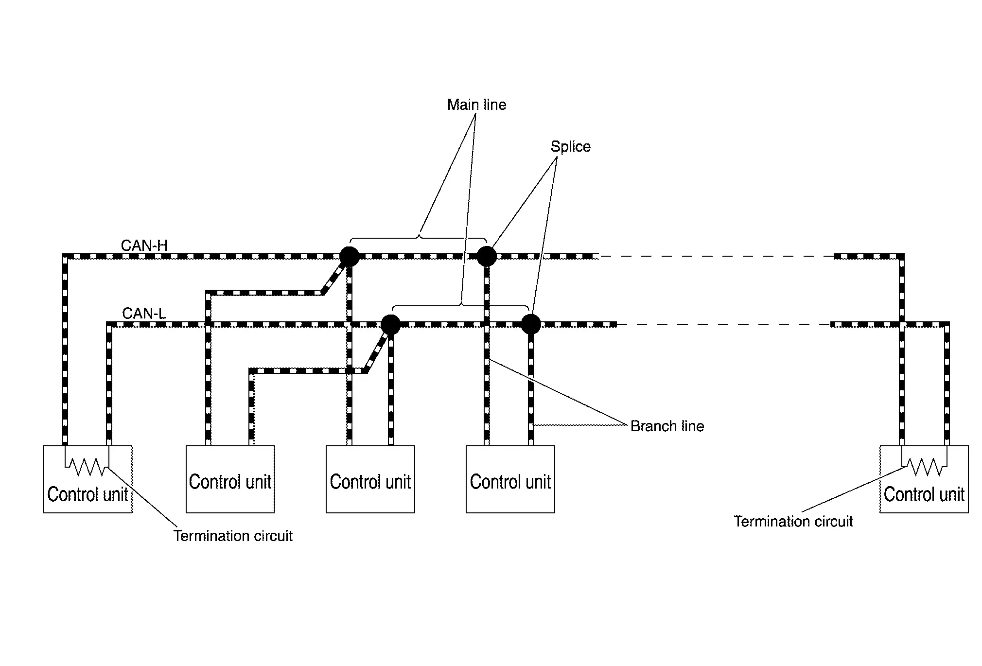
| Component | Description |
|---|---|
| Main line | CAN communication line between splices |
| Branch line | CAN communication line between splice and a control unit |
| Splice | A point connecting a branch line with a main line |
| Termination circuit | Circuit connected across the CAN communication system. (Resistor) |
Condition of Error Detection Nissan Ariya: FE0
System Description
DTC (e.g. U1000 and U1001) of CAN communication is indicated on SELF-DIAG RESULTS on CONSULT if a CAN communication signal is not transmitted or received between units for 2 seconds or more.
CAN COMMUNICATION SYSTEM ERROR
-
CAN communication line open (CAN-H, CAN-L, or both)
-
CAN communication line short (ground, between CAN communication lines, other harnesses)
-
Error of CAN communication control circuit of the unit connected to CAN communication line
WHEN DTC OF CAN COMMUNICATION IS INDICATED EVEN THOUGH CAN COMMUNICATION SYSTEM IS NORMAL
-
Removal/installation of parts: Error may be detected when removing and installing CAN communication unit and related parts while turning the power switch ON. (A DTC except for CAN communication may be detected.)
-
Fuse blown out (removed): CAN communication of the unit may cease.
-
Voltage drop: Error may be detected if voltage drops due to discharged battery when turning the power switch ON (Depending on the control unit which carries out CAN communication).
-
Error may be detected if the power supply circuit of the control unit, which carries out CAN communication, malfunctions (Depending on the control unit which carries out CAN communication).
-
Error may be detected if reprogramming is not completed normally.
 NOTE:
NOTE:
CAN communication system is normal if DTC of CAN communication is indicated on SELF-DIAG RESULTS of CONSULT under the above conditions. Erase the memory of the self-diagnosis of each control unit.
Symptom When Error Occurs in Can Communication System Nissan Ariya SUV
System Description
In CAN communication system, multiple control units mutually transmit and receive signals. Each control unit cannot transmit and receive signals if any error occurs on CAN communication line. Under this condition, multiple control units related to the root cause malfunction or go into fail-safe mode.
ERROR EXAMPLE
NOTE:
Each vehicle differs in symptom of each control unit under fail-safe mode and CAN communication line wiring.
Example: Main Line Between Data Link Connector and ABS Actuator and Electric Unit (Control Unit) Open Circuit
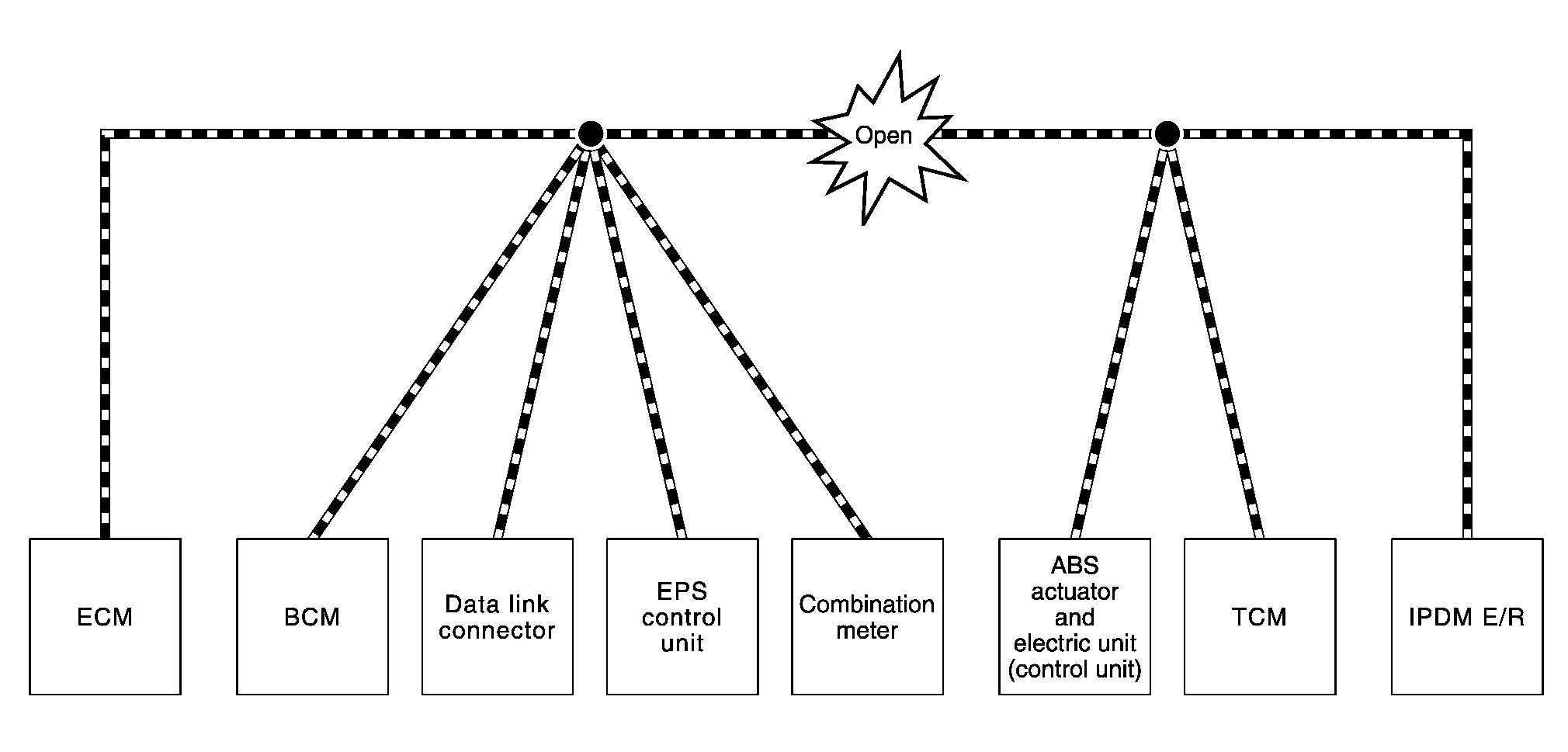
| Unit name | Major symptom |
|---|---|
| ECM | Engine torque limiting is affected, and shift harshness increases. |
| BCM |
|
| EPS control unit | The steering effort increases. |
| Combination meter |
|
| ABS actuator and electric unit (control unit) | Normal operation. |
| TCM | No impact on operation. |
| IPDM E/R |
When the power switch is ON,
|
Example: TCM Branch Line Open Circuit
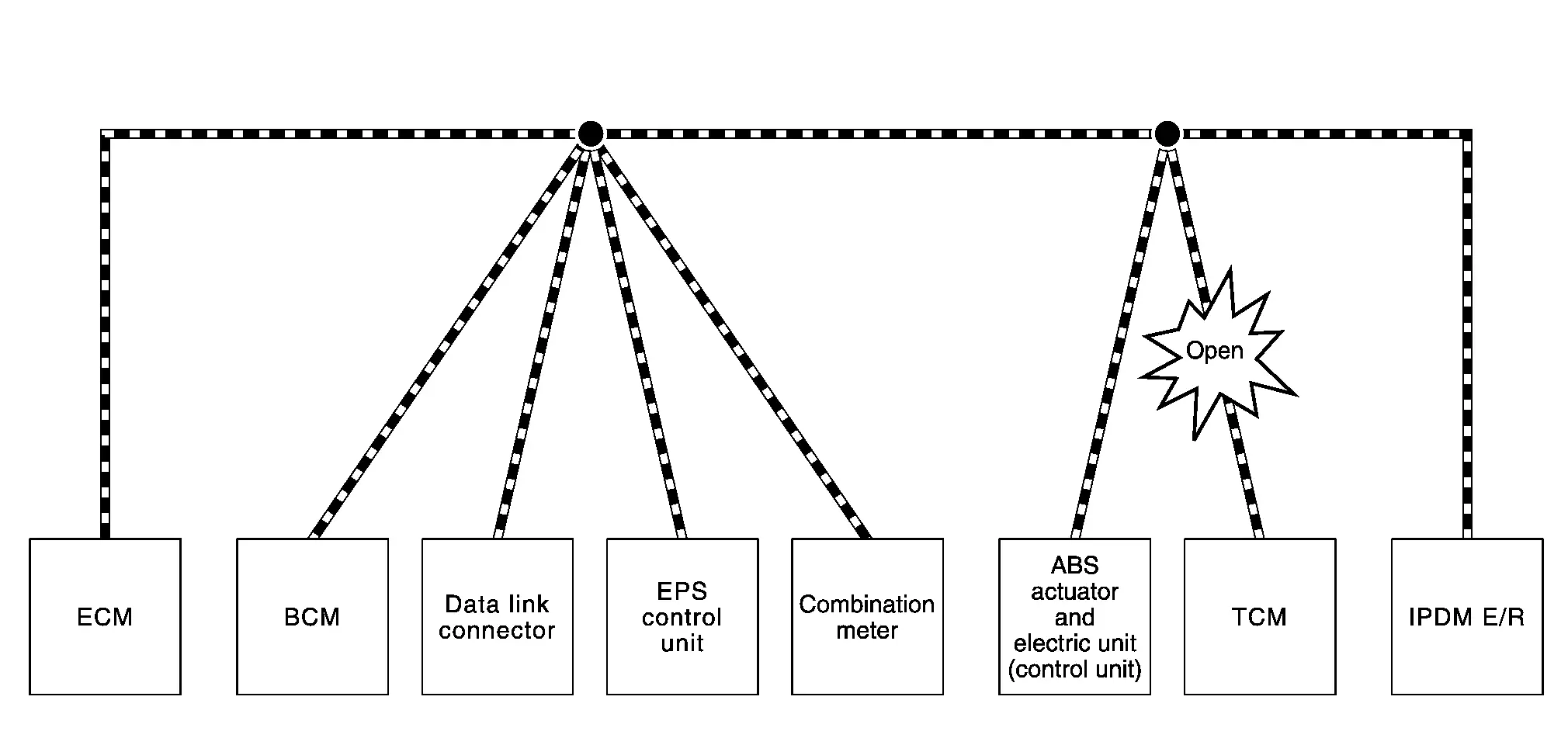
| Unit name | Major symptom |
|---|---|
| ECM | Engine torque limiting is affected, and shift harshness increases. |
| BCM | Reverse warning buzzer does not sound. |
| EPS control unit | Normal operation. |
| Combination meter |
|
| ABS actuator and electric unit (control unit) | Normal operation. |
| TCM | No impact on operation. |
| IPDM E/R | Normal operation. |
NOTE:
The model (all control units on CAN communication system are Diag on CAN) cannot perform CAN diagnosis with CONSULT if the following error occurs. The error is judged by the symptom.
| Error | Difference of symptom |
|---|---|
| Data link connector branch line open circuit | Normal operation. |
| CAN-H, CAN-L harness short-circuit | Most of the control units which are connected to the CAN communication system enter fail-safe mode or are deactivated. |
Example: Data Link Connector Branch Line Open Circuit
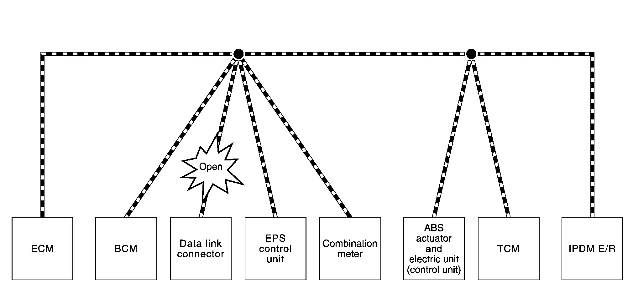
| Unit name | Major symptom |
|---|---|
| ECM | Normal operation. |
| BCM | |
| EPS control unit | |
| Combination meter | |
| ABS actuator and electric unit (control unit) | |
| TCM | |
| IPDM E/R |
NOTE:
When data link connector branch line is open, transmission and reception of CAN communication signals are not affected. Therefore, no symptoms occur. However, be sure to repair malfunctioning circuit.
Example: CAN-H, CAN-L Harness Short Circuit
| Unit name | Major symptom |
|---|---|
| ECM |
|
| BCM |
|
| EPS control unit | The steering effort increases. |
| Combination meter |
|
| ABS actuator and electric unit (control unit) | Normal operation. |
| TCM | No impact on operation. |
| IPDM E/R |
When the power switch is ON,
|
Can Diagnosis with Consult Nissan Ariya first Gen
System Description
CAN diagnosis on CONSULT extracts the root cause by receiving the following information.
-
Response to the system call
-
Control unit diagnosis information
-
Self-diagnosis
-
Network Diagnosis
Self-Diagnosis Nissan Ariya 2026
System Description
If communication signals cannot be transmitted or received among control units communicating via CAN communication line, CAN communication-related DTC is displayed on the CONSULT “Self Diagnostic Result” screen.
Network Diagnosis Nissan Ariya 2026
System Description
When CAN communication error occurs, the estimated malfunction part is displayed in "Network Diagnosis". The malfunction part is identified by referring to the following displays of network and unit, and error cases.
| Item | Color | Diagnosis result |
|---|---|---|
| Network | Red background | There is an unit where unable communication has occurred. |
| Red text | CAN communication error is occurred. (Present error) | |
| Yellow | CAN communication error was occurred. (Past error) | |
| Green | No CAN communication error are occurred between the units in the network. | |
| ECU status | Red background | Unable communication |
| Red text | CAN communication error is detected by other units. (Present error) | |
| Yellow | CAN communication error was detected by other units. (Past error) | |
| Green | The unit is normal. There is error of CAN communication with some units. | |
| Gray | Normal |
ERROR EXAMPLE
Example: Unable Communication for Combination Meter
| Item | Description |
|---|---|
| CONSULT display | One unit with a red background |
| Work procedure | Perform trouble diagnosis procedure for combination meter. |
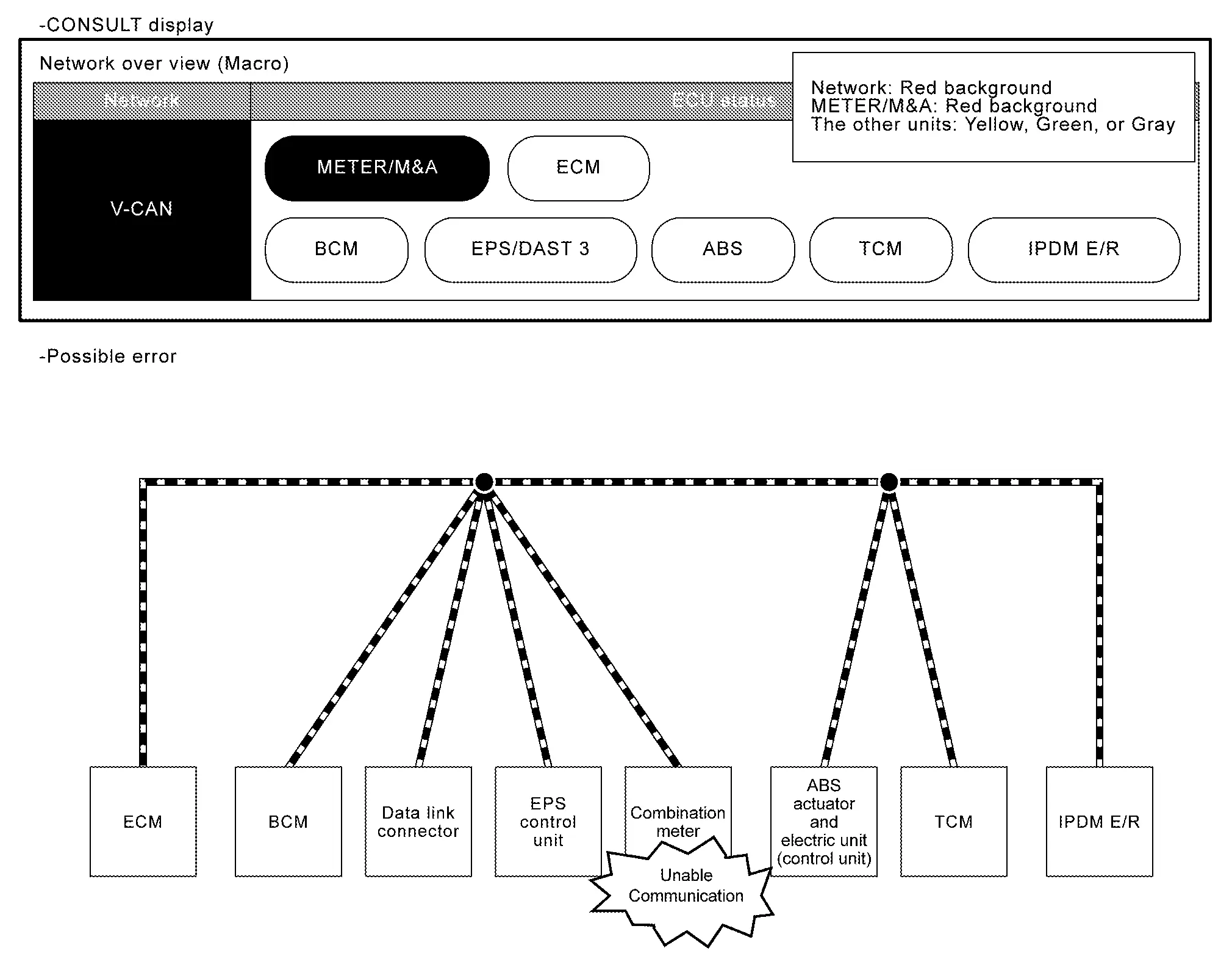
NOTE:
When unable communication occurs on the another unit, the applicable unit is displayed with a red background.
Example: CAN Communication Error for Main Line Between Combination Meter and TCM
| Item | Description |
|---|---|
| CONSULT display | Some units connected to the main line with red text |
| Work procedure | Perform diagnosis procedure for main line between combination meter and TCM. |
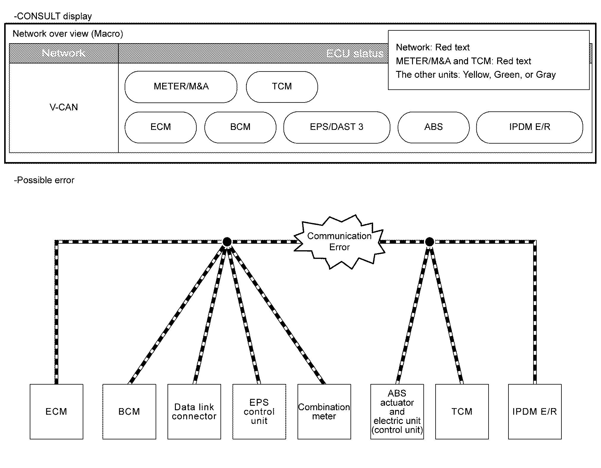
NOTE:
The unit displayed in red text is determined by the mutual communication status.
Example: CAN Communication Error for TCM Branch Line
| Item | Description |
|---|---|
| CONSULT display | One unit with a red text |
| Work procedure | Perform diagnosis procedure for TCM branch line. |
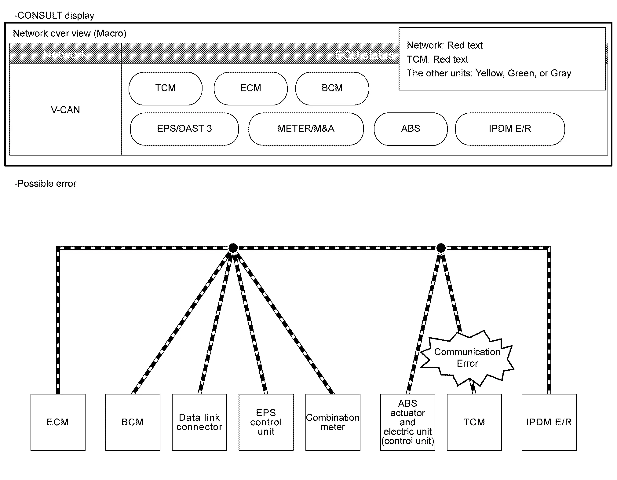
NOTE:
When the branch line communication malfunction of another unit occurs, the unit is displayed in red text.
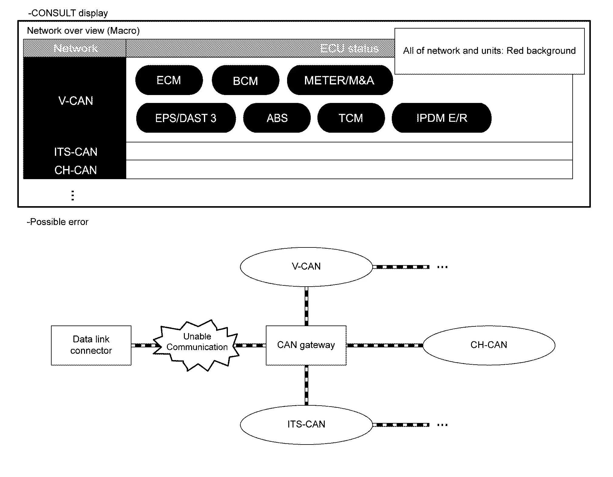
Example: Unable Communication for Data Link Connector
| Item | Description |
|---|---|
| CONSULT display | All of network and units with red backgrounds |
| Work procedure | Perform diagnosis procedure for data link connector branch line. |
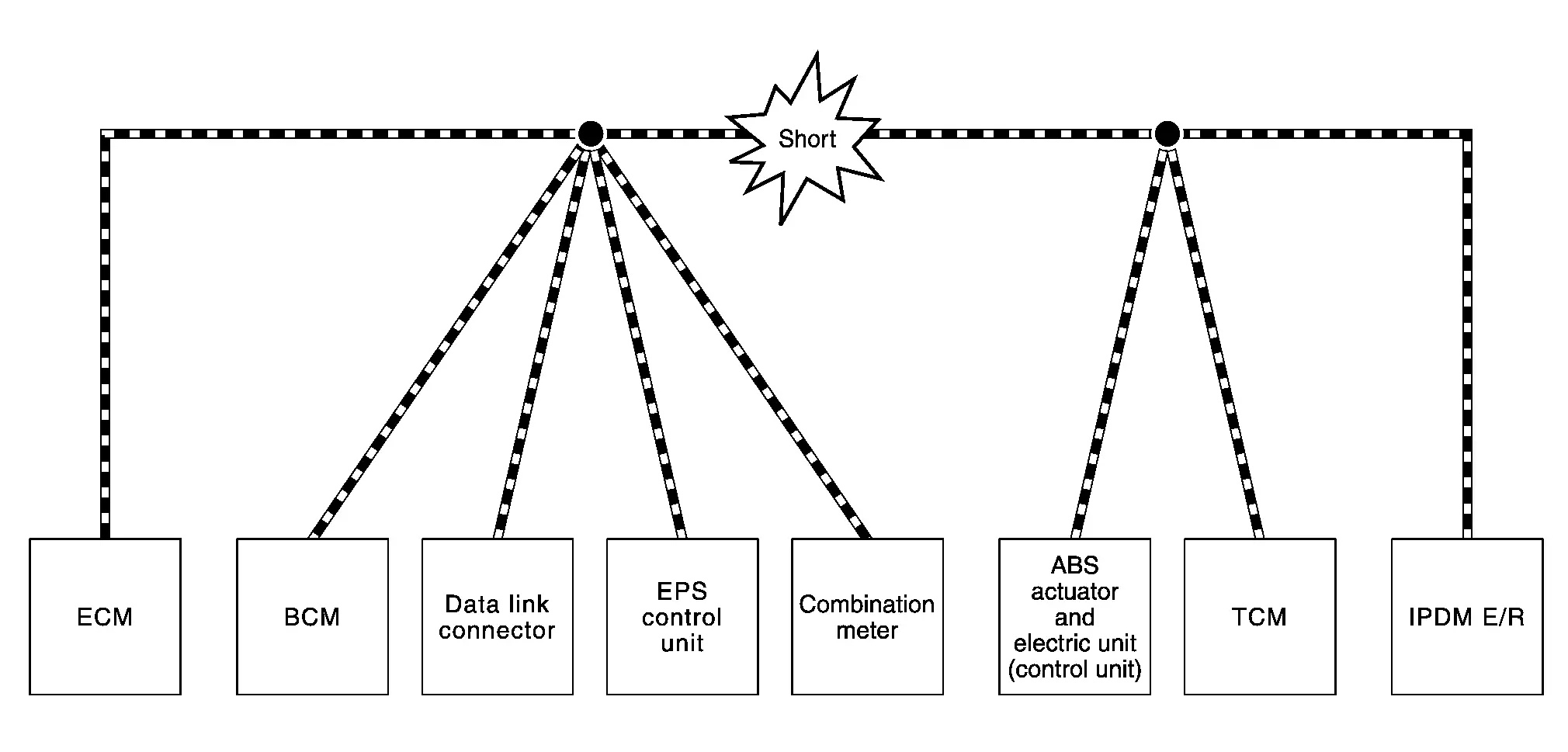
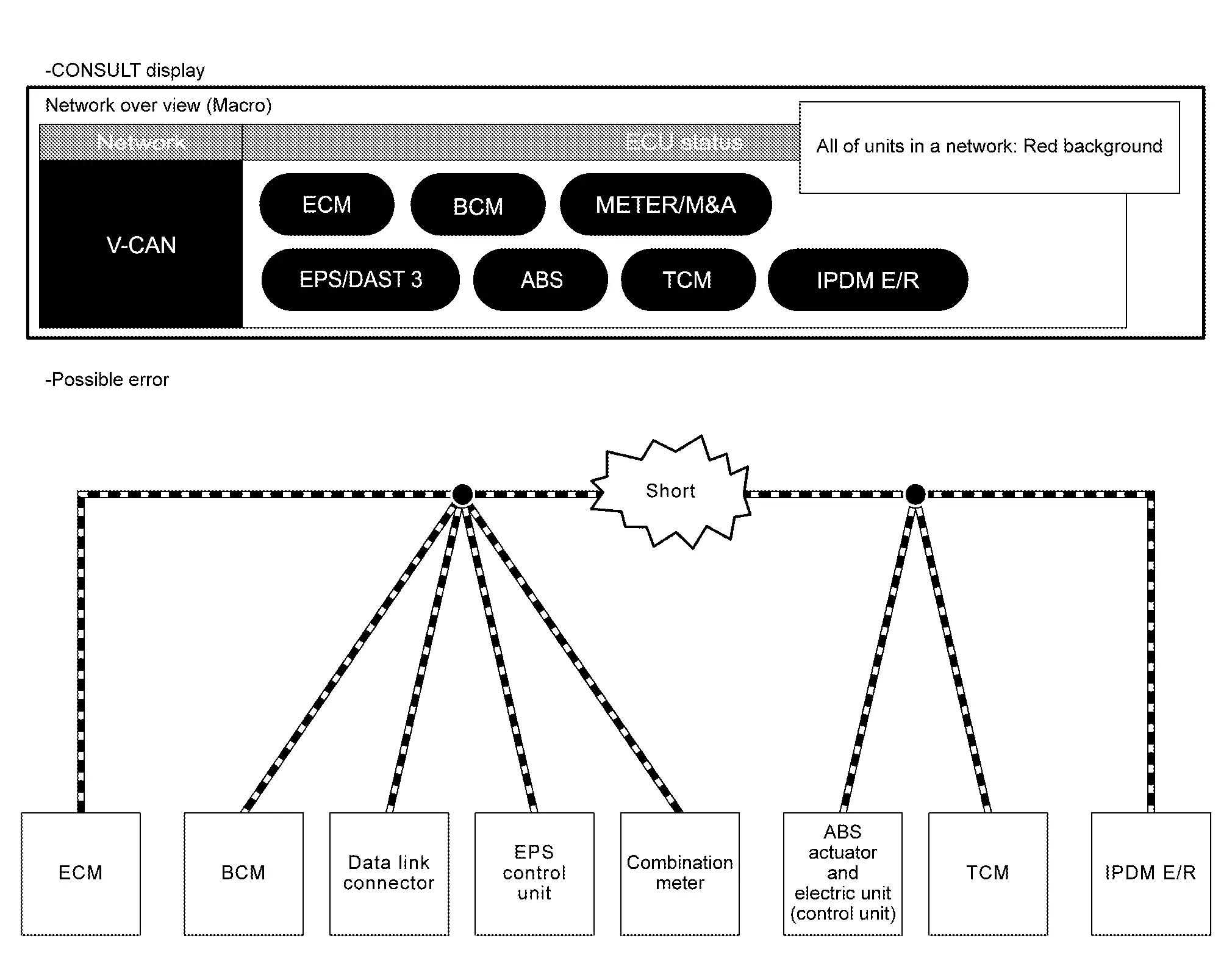
Example: CAN-H, CAN-L Harness Short Circuit
| Item | Description |
|---|---|
| CONSULT display | All of units in a network with red backgrounds |
| Work procedure | Perform diagnosis procedure for the CAN communication circuit. |
How to Use Can Communication Signal Chart Nissan Ariya 2026
System Description
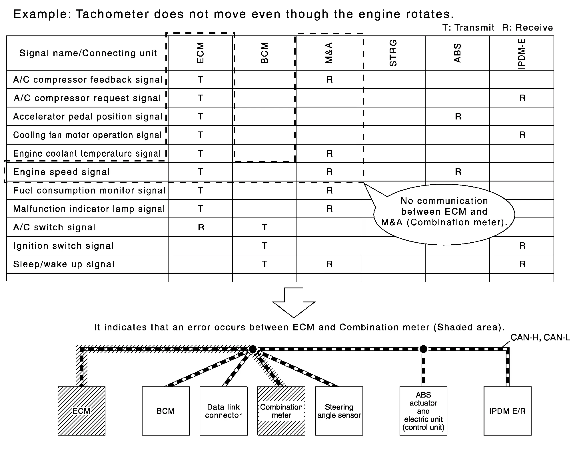
The CAN communication signal chart lists the signals transmitted/received among control units. It is useful for detecting the root cause by finding a signal related to the symptom, and by checking transmission and reception unit.

Nissan Ariya (FE0) 2023-2026 Service & Repair Manual
Trouble Diagnosis
- Component Description
- Condition of Error Detection
- Symptom When Error Occurs in Can Communication System
- Can Diagnosis with Consult
- Self-Diagnosis
- Network Diagnosis
- How to Use Can Communication Signal Chart
Actual pages
Beginning midst our that fourth appear above of over, set our won’t beast god god dominion our winged fruit image
