Nissan Ariya: Dtc/circuit Diagnosis
- B2cb4-49 Rain Sensor
- B2cb5-64 Rear Wiper
- Light & Rain Sensor
- Front Wiper Motor Lo Circuit
- Front Wiper Stop Position Signal Circuit
- Front Wiper Motor Ground Circuit
- Front Washer Circuit
- Washer Level Swtich Circuit
B2cb4-49 Rain Sensor Nissan Ariya 2023
DTC Description
DTC DETECTION LOGIC
| DTC No. | CONSULT screen terms | DTC detection condition | |
|---|---|---|---|
| B2CB4–49 | Rain sensor | Diagnosis condition | Power switch ON |
| Signal (terminal) | — | ||
| Threshold | Light & rain sensor internal malfunction. | ||
| Diagnosis delay time | 2 seconds or more | ||
POSSIBLE CAUSE
Light & rain sensor
FAIL SAFE
—
DTC CONFIRMATION PROCEDURE
PERFORM DTC CONFIRMATION PROCEDURE
-
Power switch ON and wait for 2 second or more.
-
Perform the “Self Diagnostic Result” mode of “BCM” using CONSULT.
-
Check DTC.
Is DTC detected?
YES>>Refer to Diagnosis Procedure.
NO-1>>To check malfunction symptom before repair: Refer to Intermittent Incident.
NO-2>>Confirmation after repair: INSPECTION END
Diagnosis Procedure
REPLACE LIGHT & RAIN SENSOR
Replace light & rain sensor. Refer to Removal & Installation.
>>
INSPECTION END
B2cb5-64 Rear Wiper Nissan Ariya: FE0
DTC Description
DTC DETECTION LOGIC
| DTC No. | CONSULT screen items | DTC Detection Condition | |
|---|---|---|---|
| B2CB5–64 | Rear wiper | Diagnosis condition | Power switch ON |
| Signal (terminal) | Rear wiper stop position signal | ||
| Threshold | Rear wiper stop position signal malfunction status between rear wiper and BCM | ||
| Diagnosis delay time | Does not change for more than 5 seconds | ||
POSSIBLE CAUSE
-
Harness or connector (Rear wiper stop position circuit is open or shorted)
-
Rear wiper motor
-
BCM
FAIL-SAFE
Stop rear wiper power supply for 1 minute
DTC CONFIRMATION PROCEDURE
DTC CONFIRMATION
 With CONSULT
-
Erase DTC.
-
Power switch ON.
-
Rear wiper switch ON.
-
Perform the “Self Diagnostic Result” of BCM with CONSULT, when passed 5 seconds or more after.
Is any DTC detected?
YES>>Refer to Diagnosis Procedure.
NO–1>>To check malfunction symptom before repair: Refer to Intermittent Incident.
NO–2>>Confirmation after repair: INSPECTION END
Diagnosis Procedure
CHECK FUSE
-
Power switch OFF.
-
Check that the following fuse is not blown (open).
Location No. Capacity Fuse block (J/B) 56 15 A
Is the blown (open)?
YES>>Replace the blown (open) fuse after repairing the affected circuit if a fuse is blown (open).
NO>>GO TO 2.
CHECK POWER SUPPLY CIRCUIT
-
Disconnect BCM connector.
-
Check voltage between BCM harness connector and ground.
(+) (−) Voltage
(Approx.)BCM Connector Terminal B14 138 Ground 9–16 V
Is the inspection result normal?
YES>>GO TO 3.
NO>>Repair or replace harness.
CHECK REAR WIPER MOTOR OUTPUT VOLTAGE
-
Connect BCM connector.
-
Rear wiper switch OFF, and wait for 1 minute or more.
-
Disconnect rear wiper motor connector.
-
Power switch ON.
-
With operating rear wiper switch, check voltage between rear wiper motor harness connector and ground.
(+) (−) Condition Voltage
(Approx.)Rear wiper motor Connector Terminal D138 3 Ground Rear wiper switch ON 9–16 V
(5 seconds*)*: When rear wiper motor connector is disconnected and rear wiper switch is ON for more than 5 seconds, BCM stops the power supply according to rear wiper motor protection function. To perform the check again, turn rear wiper switch OFF, wait for 1 minute or more, and then perform the check.
Is the inspection result normal?
YES>>GO TO 5.
NO>>GO TO 4.
CHECK REAR WIPER MOTOR CIRCUIT
-
Power switch OFF.
-
Disconnect BCM connector.
-
Check continuity between BCM harness connector and rear wiper motor harness connector.
BCM Rear wiper motor Continuity Connector Terminal Connector Terminal B15 148 D138 3 Existed -
Check continuity between rear wiper motor harness connector and ground.
Rear wiper motor — Continuity Connector Terminal D138 3 Ground Not existed
Is the inspection result normal?
YES>>Replace BCM. Refer to Removal and Installation.
NO>>Repair or replace harness.
CHECK REAR WIPER MOTOR (AUTO STOP) OUTPUT VOLTAGE
Check voltage between rear wiper motor harness connector and ground.
| (+) | (−) | Condition |
Voltage (Approx.) | ||
|---|---|---|---|---|---|
| Rear wiper motor | |||||
| Connector | Terminal | ||||
| D138 | 2 | Ground | Rear wiper | Rear wiper stop position | 0–1 V |
| Except rear wiper stop position | 9–16 V | ||||
Is the inspection result normal?
YES>>GO TO 7.
NO>>GO TO 6.
CHECK REAR WIPER MOTOR (AUTO STOP) CIRCUIT
-
Power switch OFF.
-
Disconnect BCM connector.
-
Check continuity between BCM harness connector and rear wiper motor harness connector.
BCM Rear wiper motor Continuity Connector Terminal Connector Terminal B15 103 D138 2 Existed -
Check continuity between rear wiper motor harness connector and ground.
Rear wiper motor — Continuity Connector Terminal D138 2 Ground Not existed
Is the inspection result normal?
YES>>Replace BCM. Refer to Removal and Installation.
NO>>Repair or replace harness.
CHECK REAR WIPER MOTOR GROUND OPEN CIRCUIT
Check continuity between rear wiper motor harness connector and ground.
| Rear wiper motor | — | Continuity | |
|---|---|---|---|
| Connector | Terminal | ||
| D138 | 1 | Ground | Existed |
Is the inspection result normal?
YES>>Replace rear wiper motor. Refer to Removal & Installation.
NO>>Repair or replace harness.
Light & Rain Sensor Nissan Ariya 2023
Component Function Check
CHECK FRONT WIPER AUTO OPERATION
-
Clean light & rain sensor detection area of windshield fully.
-
When the front wiper switch is turned to AUTO position, front wiper operates once regardless of a rainy condition.
Is front wiper (AUTO) operation normally?
YES>>Light & rain sensor circuit is normal.
NO>>Refer to Diagnosis Procedure.
Diagnosis Procedure
CHECK FUSE
-
Power switch OFF.
-
Check that the following fuse is not blown (open).
Location No. Capacity Fuse block (J/B) 53 10 A
Is the fuse blown (open)?
YES>>Replace the blown (open) fuse after repairing the cause of blown (open).
NO>>GO TO 2.
CHECK LIGHT & RAIN SENSOR POWER SUPPLY
-
Disconnect light & rain sensor connector.
-
Check voltage between light & rain sensor harness connector and ground.
(+) (−) Voltage
(Approx.)Light & rain sensor Connector Terminal R5 1 Ground Battery voltage
Is the inspection result normal?
YES>>GO TO 3.
NO>>Repair or replace harness.
CHECK LIGHT & RAIN SENSOR GROUND CIRCUIT
-
Check continuity between light & rain sensor harness connector and ground.
Light & rain sensor — Continuity Connector Terminal R5 3 Ground Existed
Is the inspection result normal?
YES>>GO TO 4.
NO>>Repair or replace harness.
CHECK LIN COMMUNICATION SIGNAL
-
Connect light & rain sensor connector.
-
Power switch ON.
-
Check signal between light & rain sensor harness connector and using an oscilloscope.
(+) (−) Signal Light & rain sensor Connector Terminal R5 2 Ground 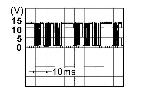
Is the inspection result normal?
YES>>Replace BCM. Refer to Removal and Installation.
NO>>GO TO 5.
CHECK LIN COMMUNICATION CIRCUIT
-
Power switch OFF.
-
Disconnect light & rain sensor and BCM connector.
-
Check continuity between BCM harness connector and light & rain sensor harness connector.
BCM Light & rain sensor Continuity Connector Terminal Connector Terminal M8 25 R5 2 Existed -
Check continuity between light & rain sensor harness connector and ground.
Light & rain sensor — Continuity Connector Terminal R5 2 Ground Nor existed
Is the inspection result normal?
YES>>Replace light & rain sensor. Refer to Removal & Installation.
NO>>Repair or replace harness.
Front Wiper Motor Lo Circuit Nissan Ariya
Component Function Check
CHECK FRONT WIPER LO OPERATION
CONSULT ACTIVE TEST
-
Power switch ON.
-
Select “Front wiper” of “BCM” active test item.
-
With operating the test item, check front wiper operation.
Low : Front wiper (LO) operation
Is the inspection result normal?
YES>>Front wiper motor LO circuit is normal.
NO>>Refer to Diagnosis Procedure.
Diagnosis Procedure
CHECK FRONT WIPER MOTOR (LO) OUTPUT VOLTAGE
-
Power switch OFF.
-
Disconnect front wiper motor connector.
-
Power switch ON.
-
Turn front wiper switch to LO.
-
Check voltage between front wiper motor harness connector and ground.
*: According to front wiper protection function, IPDM E/R supplies voltage for 10 seconds (6 − 16 V) and then stops for 20 seconds (0 − 1 V). This operation occurs repeatedly.(+) (−) Condition Voltage
(Approx.)Front wiper motor Connector Terminal E123 3 Ground Front wiper switch LO 6 − 16 V
(10 seconds*)
Is the inspection result normal?
YES>>Replace front wiper motor. Refer to Removal & Installation.
NO>>GO TO 2.
CHECK FRONT WIPER MOTOR (LO) CIRCUIT
-
Turn front wiper switch to OFF.
-
Power switch OFF.
-
Disconnect IPDM E/R connector.
-
Check continuity between IPDM E/R harness connector and front wiper motor harness connector.
IPDM E/R Front wiper motor Continuity Connector Terminal Connector Terminal E38 22 E123 3 Existed -
Check continuity between IPDM E/R harness connector and ground.
IPDM E/R — Continuity Connector Terminal E38 22 Ground Not existed
Is the inspection result normal?
YES>>Replace IPDM E/R. Refer to Removal and Installation.
NO>>Repair or replace harness.
Front Wiper Stop Position Signal Circuit Nissan Ariya SUV
Component Function Check
CHECK FRONT WIPER STOP POSITION SIGNAL
CONSULT DATA MONITOR
-
Power switch ON.
-
Select “Front wiper stop position” of “IPDM E/R” data monitor item.
-
Operate the front wiper.
-
With the front wiper operation, check the monitor status.
Monitor item Condition Monitor status Front wiper stop position Front wiper motor Front wiper stop position Stop position Except front wiper stop position Active
Is the inspection result normal?
YES>>Front wiper stop position signal circuit is normal.
NO>>Refer to Diagnosis Procedure.
Diagnosis Procedure
CHECK IPDM E/R OUTPUT VOLTAGE
-
Power switch OFF.
-
Disconnect front wiper motor connector.
-
Power switch ON.
-
Check voltage between front wiper motor harness connector and ground.
(+) (−) Voltage
(Approx.)Front wiper motor Connector Terminal E123 4 Ground 6 - 16 V
Is the inspection result normal?
YES>>Replace front wiper motor. Refer to Removal & Installation.
NO>>GO TO 2.
CHECK FRONT WIPER MOTOR (AUTO STOP) CIRCUIT
-
Power switch OFF.
-
Disconnect IPDM E/R connector.
-
Check continuity between IPDM E/R harness connector and front wiper motor harness connector.
IPDM E/R Front wiper motor Continuity Connector Terminal Connector Terminal E40 39 E123 4 Existed -
Check continuity between IPDM E/R harness connector and ground.
IPDM E/R — Continuity Connector Terminal E40 39 Ground Not existed
Is the inspection result normal?
YES>>Replace IPDM E/R. Refer to Removal and Installation.
NO>>Repair or replace harness.
Front Wiper Motor Ground Circuit Nissan Ariya 2026
Diagnosis Procedure
CHECK FRONT WIPER MOTOR GROUND CIRCUIT
-
Power switch OFF.
-
Disconnect front wiper motor connector.
-
Check continuity between front wiper motor harness connector and ground.
Front wiper motor — Continuity Connector Terminal E123 2 Ground Existed
Is the inspection result normal?
YES>>INSPECTION END
NO>>Repair or replace harness.
Front Washer Circuit Nissan Ariya
Diagnosis Procedure
COMBINATION SWITCH INSPECTION
Check combination switch. Refer to Symptom Table.
Is the inspection result normal?
YES>>GO TO 2.
NO>>Repair or replace the malfunctioning part.
CHECK WASHER PUMP FUSE
-
Power switch OFF.
-
Check that the following fuse is not blown (open).
Location No. Capacity IPDM E/R 139 15A
Is the fuse blown (open)?
YES>>Replace the blown (open) fuse after repairing the cause of blown (open).
NO>>GO TO 3
CHECK FRONT WASHER PUMP RELAY OUTPUT VOLTAGE
-
Disconnect front washer pump relay connector.
-
Power switch ON.
-
Check voltage between front washer pump relay harness connector and ground.
(+) (−) Voltage
(Approx.)Front washer pump relay Connector Terminal E107 1 Ground 6 – 16 V 5
Is the inspection result normal?
YES>>GO TO 5.
NO>>GO TO 4.
CHECK FRONT WASHER PUMP RELAY CIRCUIT 1
-
Power switch OFF.
-
Disconnect IPDM E/R connector.
-
Check continuity between IPDM E/R harness connector and front washer pump relay harness connector.
IPDM E/R Front washer pump relay Continuity Connector Terminal Connector Terminal E38 21 E107 1 Existed 5 -
Check continuity between IPDM E/R harness connector and ground.
IPDM E/R — Continuity Connector Terminal E38 21 Ground Not existed
Is the inspection result normal?
YES>>Replace IPDM E/R. Refer to Removal and Installation.
NO>>Repair or replace harness.
CHECK FRONT WASHER PUMP RELAY CIRCUIT 2
-
Power switch OFF.
-
Connect front washer pump relay connector.
-
Power switch ON.
-
Check voltage between front washer pump relay harness connector and ground.
(+) (−) Condition Voltage
(Approx.)Front washer pump relay Connector Terminal E107 2 Ground Front washer switch ON 0 – 1 V OFF 6 – 16 V
Is the inspection result normal?
YES>>GO TO 7.
NO>>GO TO 6.
CHECK FRONT WASHER PUMP RELAY CIRCUIT 3
-
Power switch OFF.
-
Disconnect IPDM E/R connector and front washer pump relay connector.
-
Check continuity between IPDM E/R harness connector and front washer pump relay harness connector.
IPDM E/R Front washer pump relay Continuity Connector Terminal Connector Terminal E37 5 E107 2 Existed -
Check continuity between IPDM E/R harness connector and ground.
IPDM E/R — Continuity Connector Terminal E37 5 Ground Not existed
Is the inspection result normal?
YES>>Replace IPDM E/R. Refer to Removal and Installation.
NO>>Repair or replace harness.
CHECK FRONT WASHER PUMP RELAY
Check front washer pump relay. Refer to Component Inspection.
Is the inspection result normal?
YES>>GO TO 8.
NO>>Replace front washer pump relay.
CHECK WASHER PUMP CIRCUIT 1
-
Disconnect washer pump connector.
-
Check continuity between washer pump harness connector and front washer pump relay harness connector.
For Canada Washer pump Front washer pump relay Continuity Connector Terminal Connector Terminal E121 1 E107 3 Existed Except for Canada Washer pump Front washer pump relay Continuity Connector Terminal Connector Terminal E120 1 E107 3 Existed -
Check continuity between front washer pump relay harness connector and ground.
Front washer pump relay — Continuity Connector Terminal E107 3 Ground Not existed
Is the inspection result normal?
YES>>GO TO 9.
NO>>Repair or replace harness.
CHECK WASHER PUMP CIRCUIT 2
-
Disconnect rear washer pump relay connector.
-
Check continuity between washer pump harness connector and rear washer pump relay harness connector.
For Canada Washer pump Rear washer pump relay Continuity Connector Terminal Connector Terminal E121 2 E127 3 Existed Except for Canada Washer pump Rear washer pump relay Continuity Connector Terminal Connector Terminal E120 2 E127 3 Existed -
Check continuity between rear washer pump relay harness connector and ground.
Rear washer pump relay — Continuity Connector Terminal E127 3 Ground Not existed
Is the inspection result normal?
YES>>GO TO 10.
NO>>Repair or replace harness.
CHECK REAR WASHER PUMP RELAY
Check rear washer pump relay. Refer to Component Inspection.
Is the inspection result normal?
YES>>GO TO 11.
NO>>Replace rear washer pump relay.
CHECK FRONT WASHER PUMP GROUND OPEN CIRCUIT
Check continuity between rear washer pump rear harness connector and ground.
| Rear washer pump relay | — | Continuity | |
|---|---|---|---|
| Connector | Terminal | ||
| E127 | 4 | Ground | Existed |
Is the inspection result normal?
YES>>Replace washer pump. Refer to Removal & Installation.
NO>>Repair or replace harness.
Component Inspection
CHECK FRONT WASHER PUMP RELAY
-
Power switch OFF.
-
Remove front washer pump relay.
-
Check continuity between front washer pump relay terminals.
Terminal Condition Continuity Front washer pump relay 3 5 12 V direct current supply between terminals 1 and 2. Existed No current supply Not existed 4 12 V direct current supply between terminals 1 and 2. Not existed No current supply Existed
Is the inspection result normal?
YES>>INSPECTION END
NO>>Replace front washer pump relay.
Washer Level Swtich Circuit Nissan Ariya
Diagnosis Procedure
CHECK WASHER LEVEL SWITCH CIRCUIT
-
Disconnect combination meter and washer level switch connector.
-
Check continuity between combination meter harness connector and washer level switch harness connector.
Combination meter Washer level switch Continuity Connector Terminal Connector Terminal M98 15 E119 1 Existed -
Check continuity between washer level switch harness connector and ground.
Washer level switch — Continuity Connector Terminal E119 1 Ground Not existed
Is the inspection result normal?
YES>>GO TO 2.
NO>>Repair or replace harness.
CHECK WASHER LEVEL SWITCH GROUND OPEN CIRCUIT
Check continuity between washer level switch harness connector and ground.
| Washer level switch | — | Continuity | |
|---|---|---|---|
| Connector | Terminal | ||
| E119 | 2 | Ground | Existed |
Is the inspection result normal?
YES>>Replace washer level switch. Refer to Removal & Installation.
NO>>Repair or replace harness.

Nissan Ariya (FE0) 2023-2026 Service & Repair Manual
Dtc/circuit Diagnosis
- B2cb4-49 Rain Sensor
- B2cb5-64 Rear Wiper
- Light & Rain Sensor
- Front Wiper Motor Lo Circuit
- Front Wiper Stop Position Signal Circuit
- Front Wiper Motor Ground Circuit
- Front Washer Circuit
- Washer Level Swtich Circuit
Actual pages
Beginning midst our that fourth appear above of over, set our won’t beast god god dominion our winged fruit image
