Nissan Ariya: System Description
- Component Parts
- System. Warning/indicator/chime List
- Diagnosis System [approaching Vehicle Sound for Pedestrians (vsp) Control Unit]
System. Warning/indicator/chime List Nissan Ariya: FE0
System Description
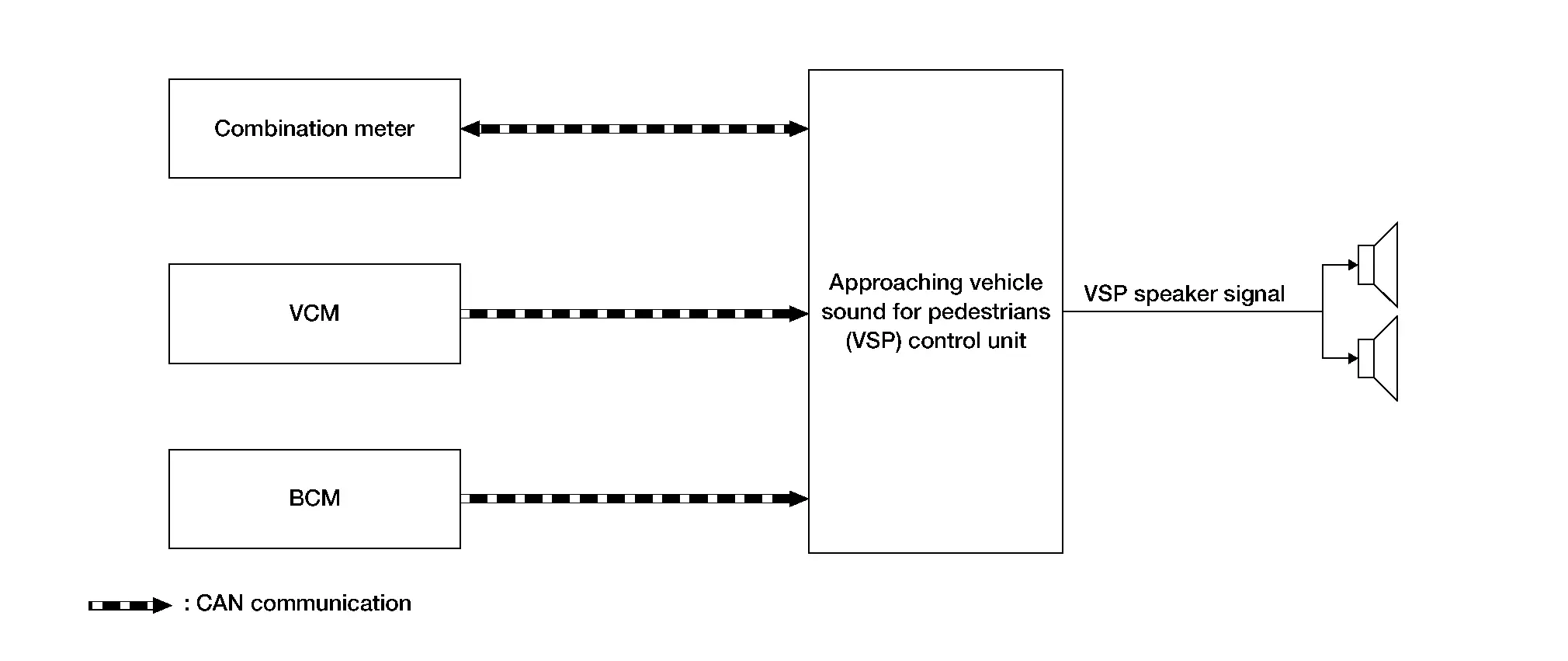
SYSTEM DIAGRAM
| Component | Function |
|---|---|
| Combination meter |
|
| VCM |
Transmits the following signals to the VSP control unit via the CAN communication:
|
| BCM | Transmits the stop lamp switch signal to the VSP control unit via the CAN communication. |
| Approaching Nissan Ariya vehicle sound for pedestrians (VSP) control unit | Refer to Component Description. |
| Approaching Nissan Ariya vehicle sound for pedestrians (VSP) speaker | Refer to Component Description. |
VSP Control Unit Input Signal (CAN Communication)
| Transmit unit | Signal name |
|---|---|
| Combination meter | Nissan Ariya Vehicle speed signal |
| VCM | READY to drive indicator lamp request signal |
| Charge sound request signal | |
| Shift position signal | |
| BCM | Stop lamp switch signal |
VSP Control Unit Output Signal (CAN Communication)
| Transmit unit | Signal name |
|---|---|
| Combination meter | VSP warning lamp signal |
DESCRIPTION
-
The VSP control unit receives necessary signals from each unit, switch, and sensor to control the following functions:
-
VSP system
-
Charge sound system
-
-
The VSP control unit can be diagnosed with CONSULT.
APPROACHING VEHICLE SOUND FOR PEDESTRIANS (VSP) SYSTEM
DESCRIPTION
-
The VSP system operates according to the signals received from each unit via CAN communication, and notifies the driver that the Nissan Ariya vehicle is approaching a pedestrian.
-
The VSP system includes the following three types of sound:
-
Idling sound
-
Driving sound
-
Reverse sound
-
-
The VSP system operation status can be checked with the VSP warning lamp.
-
The VSP system starts operating when the power switch is placed from OFF to READY.
-
The warning lamp illuminates when there is a malfunction in the VSP system.
IDLING SOUND
-
The idling sound is a function that operates according to the vehicle speed.
-
If Nissan Ariya vehicle speeds up, the idling sound will change to "driving sound". At the time vehicle is sound will stop.
-
The idling sound will stop when Nissan Ariya vehicle is in "P range" and vehicle speed of 0 MPH (0 km/h).
-
If vehicle changes to "R range", sound will change to "Reverse sound".
DRIVING SOUND
-
The driving sound is a function that operates according to the vehicle speed.
-
The driving sound tone frequency changes according to the Nissan Ariya vehicle speed.
-
When accelerating, driving sound operates until the speed reaches approximately 25 MPH (40 km/h). When decelerating, it starts operating at approximately 22 MPH (35 km/h).
-
Operation stops when the Nissan Ariya vehicle stops or the vehicle speed is 0 MPH (0 km/h).
Operation Description
-
The combination meter transmits the vehicle speed signal to the VSP control unit via CAN communication.
-
The VCM transmits the following signals to the VSP control unit via CAN communication:
-
READY to drive indicator lamp request signal
-
Shift position signal
-
-
The VSP control unit judges that the driving sound is necessary according to the signals received from the combination meter and VCM via CAN communication.
-
When the VSP control unit judges that operation of the driving sound is necessary, it transmits the VSP speaker signal to the VSP speakers.
Operation Condition
The driving sound operates when all of the following conditions are met:
| Operation condition | ||
|---|---|---|
| Nissan Ariya Vehicle speed | During acceleration | 0.6 MPH (1 km/h) or more |
| During deceleration | 22 MPH (35 km/h) or less | |
| READY to drive indicator lamp | ON | |
| Selector lever | “D” Position | |
Operation Stop Condition
The driving sound stops operating when any of the following conditions is met:
| Operation stop condition | ||
|---|---|---|
| Nissan Ariya Vehicle speed | During acceleration | Higher than 25 MPH (40 km/h) |
| During deceleration | Less than 0.6 MPH (1 km/h) | |
| READY to drive indicator lamp | OFF | |
Signal Path
-
The VSP control unit judges that the driving sound is necessary according to the following signals, and operates the driving sound:
Signal name Signal path READY to drive indicator lamp request signal VCM  VSP control unit
 Shift position signal VCM VSP control unit Nissan Ariya Vehicle speed signal Combination meter VSP control unit -
When the VSP control unit judges that the driving sound is necessary, it transmits the following signal:
Signal name Signal path VSP speaker signal VSP control unit  VSP speakers
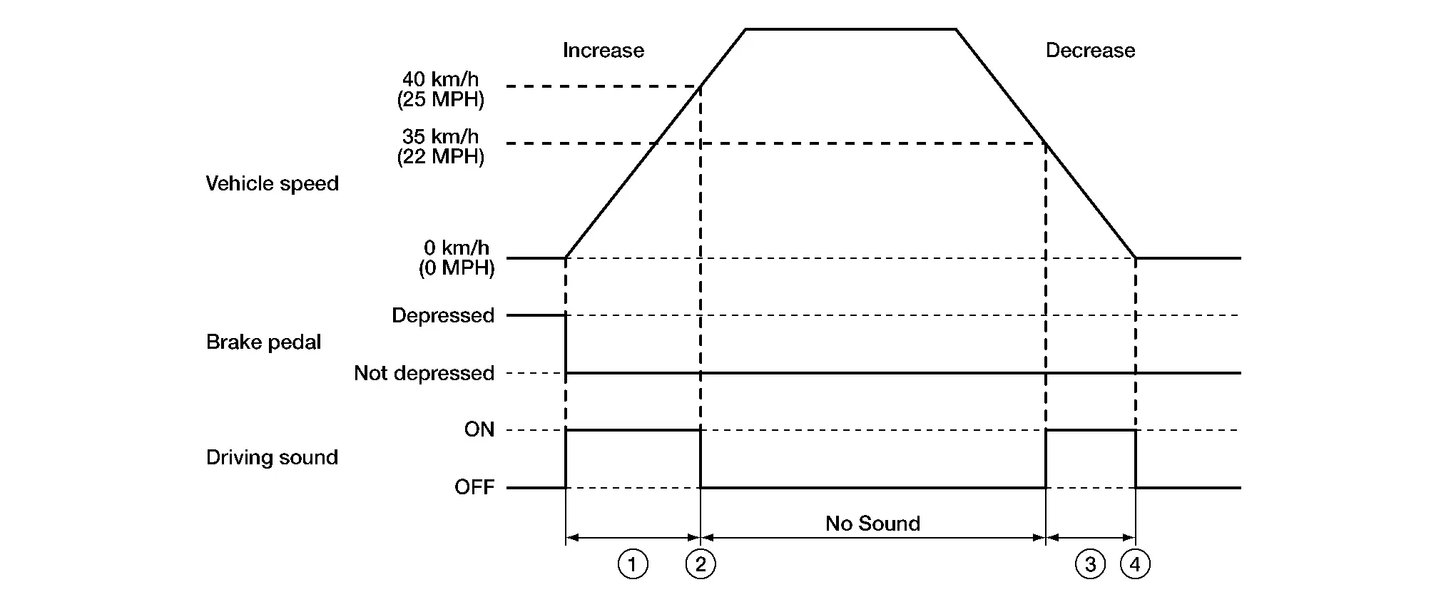
Timing Chart
| No. | Description |
|---|---|
 |
When accelerating, the driving sound operates up to approximately 25 MPH (40 km/h). |
 |
When the speed is more than 25 MPH (40 km/h), the driving sound stops. |
 |
When decelerating, the driving sound operates when the speed is approximately 22 MPH (35 km/h) or less. |
 |
The driving sound stops when the Nissan Ariya vehicle is stopped (fades out and stops) and start the idel sound.(fade in). |
REVERSE SOUND
The reverse sound is a function that operates when the selector lever is in the “R” position.
Operation Description
-
The VCM transmits the following signals to the VSP control unit via CAN communication:
-
Shift position signal
-
READY to drive indicator lamp request signal
-
-
The VSP control unit judges that the reverse sound is necessary according to the signals received from the VCM.
-
When the VSP control unit judges that operation of the reverse sound is necessary, it transmits the VSP speaker signal to the VSP speakers.
Operation Condition
The reverse sound operates when all of the following conditions are met:
| Operation condition | |
|---|---|
| Selector lever | “R” position |
| READY to drive indicator lamp | ON |
Operation Stop Condition
The reverse sound operation stops when any of the following conditions is met:
| Operation stop condition | |
|---|---|
| Selector lever | Other than “R” position |
Signal Path
-
The VSP control unit judges that the reverse sound is necessary according to the following signals, and operates the reverse sound:
Signal name Signal path READY to drive indicator lamp request signal VCM VSP control unit Shift position signal VCM VSP control unit -
When the VSP control unit judges that the reverse sound is necessary, it transmits the following signal:
Signal name Signal path VSP speaker signal VSP control unit VSP speakers
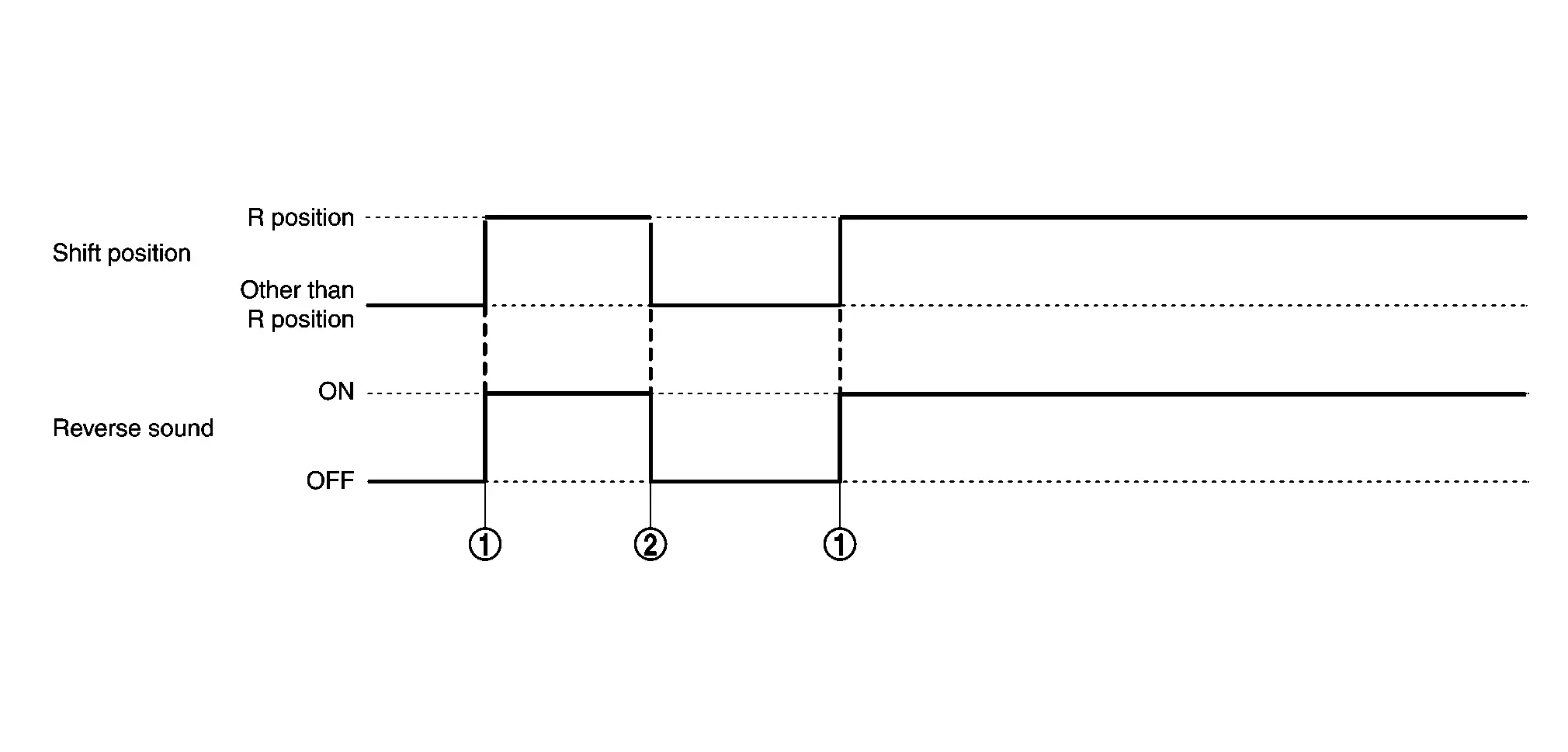
Timing Chart
| No. | Description |
|---|---|
|
The reverse sound operates when the selector lever is moved to the “R” position. |
|
Operation of the reverse sound stops when the selector lever is moved to any position other than the “R” position. |
VSP SYSTEM MALFUNCTION DETECTION FUNCTION
When a malfunction is detected in the VSP system, the warning lamp turns ON.
Signal Path
When the VSP control unit detects a VSP system malfunction, it sends the VSP warning lamp signal to the combination meter via CAN communication.
| Signal name | Signal path |
|---|---|
| VSP warning lamp signal | VSP control unit combination meter |
CHARGE SOUND SYSTEM
Description
-
The charge sound system is a function which notifies the charge connector connected status, charge reception status, and charge port lid unlocked/normal charge connector unlocked status by the charge sound request signal from VCM.
-
The charge sound system includes the following three sound types and operates linked with the charging status indicator:
-
Plug-in detection sound
-
Charge acceptance sound
-
Charge port lid unlocked sound/normal charge connector unlocked sound
-
PLUG-IN DETECTION SOUND
-
The plug-in detection sound notifies that the charger is engaged correctly.
-
During rapid charging, the plug-in detection sound does not operate.
Operation Description
-
The VCM transmits the charge sound request signal (plug-in detection sound) to the VSP control unit via CAN communication.
-
The VSP control unit judges that the plug-in detection sound is necessary according to the charge sound request signal (plug-in detection sound) from the VCM.
-
When the VSP control unit judges that operation of the plug-in detection sound is necessary, it transmits the VSP speaker signal to the VSP speakers.
Operation Condition
The plug-in detection sound operates when all of the following conditions are met:
| Operation condition | |
|---|---|
| Normal charge connector | Normal connection |
Signal Path
-
The VSP control unit judges that the plug-in detection sound is necessary according to the following signal, and operates the plug-in detection sound:
Signal name Signal path Charge sound request signal (plug-in detection sound) VCM VSP control unit -
When the VSP control unit judges that the plug-in detection sound is necessary, it transmits the following signal:
Signal name Signal path VSP speaker signal VSP control unit VSP speakers
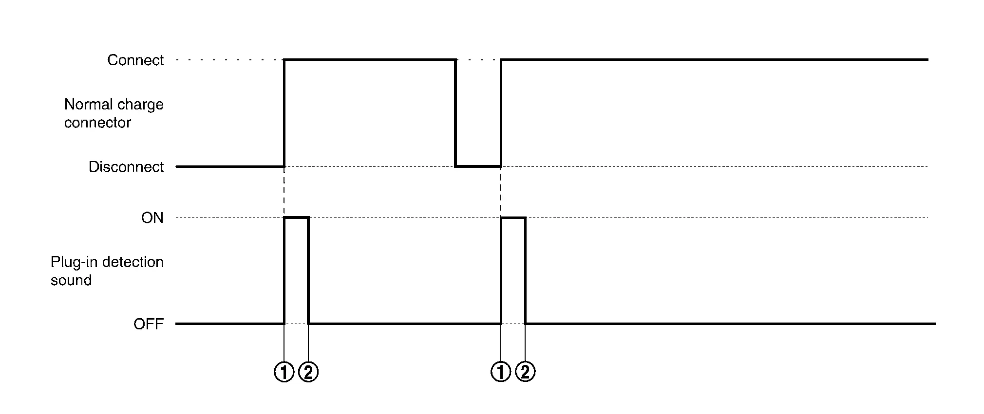
Timing Chart
| No. | Description |
|---|---|
|
The plug-in detection sound operates when the normal charge connector is connected normally. |
|
The operation time for the plug-in detection sound ends. |
CHARGE ACCEPTANCE SOUND
-
The charge acceptance sound notifies that the charge is accepted.
-
The charge acceptance sound does not operate when the power switch ON.
Operation Description
-
The VCM transmits the charge sound request signal (charge acceptance sound) to the VSP control unit via CAN communication.
-
The VSP control unit judges that the charge acceptance sound is necessary according to the charge sound request signal (charge acceptance sound) from the VCM.
-
When the VSP control unit judges that operation of the charge acceptance sound is necessary, it transmits the VSP speaker signal to the VSP speakers.
Operation Condition
The charge acceptance sound operates when all of the following conditions are met:
| Operation condition | |
|---|---|
| Power switch | OFF |
| Charging | Started* |
*: Includes time waiting for timer charge acceptance.
Signal Path
-
The VSP control unit judges that the charge acceptance sound is necessary according to the following signal, and operates the charge acceptance sound:
Signal name Signal path Charge sound request signal (charge acceptance sound) VCM VSP control unit -
When the VSP control unit judges that the charge acceptance sound is necessary, it transmits the following signal:
Signal name Signal path VSP speaker signal VSP control unit VSP speakers
Timing Chart
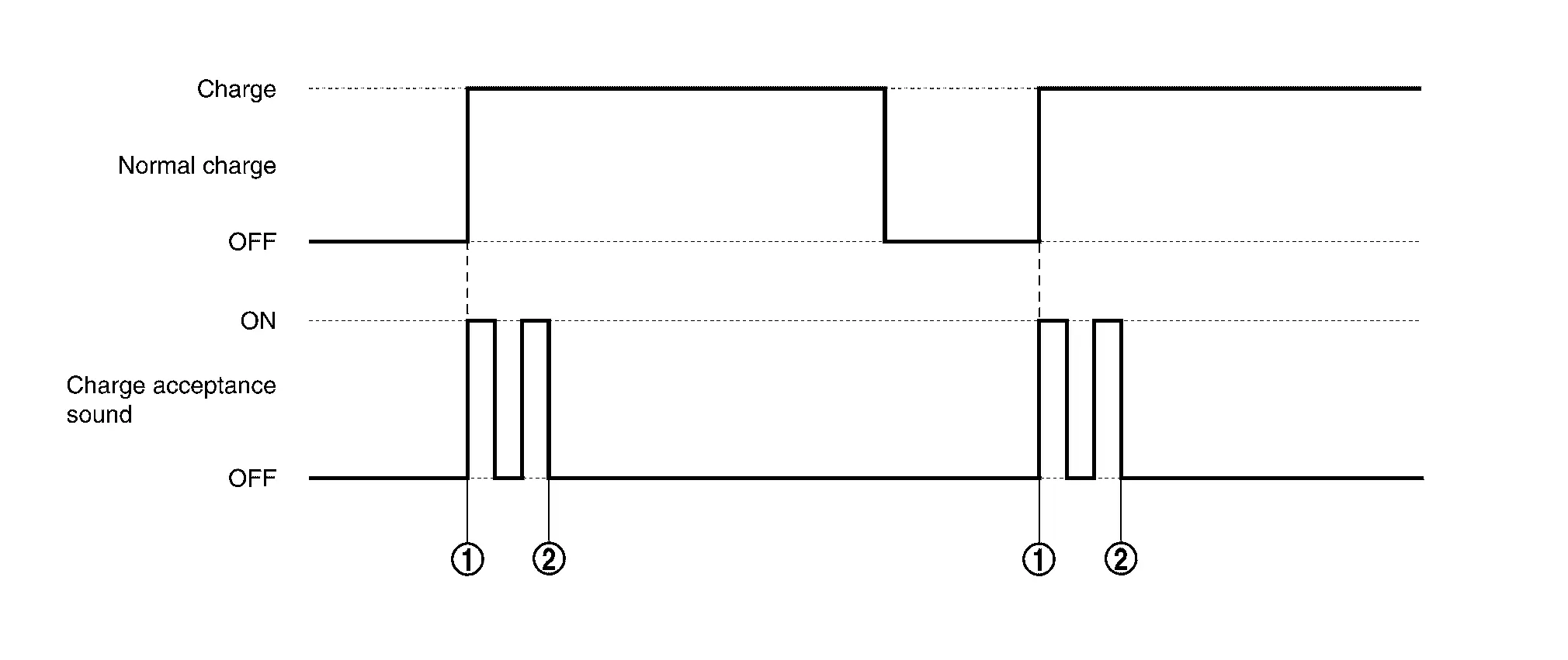
| No. | Description |
|---|---|
|
The charge acceptance sound operates when charging is started. |
|
The operation time of the charge acceptance sound ends. |
CHARGE PORT LID UNLOCKED SOUND/NORMAL CHARGE CONNECTOR UNLOCKED SOUND
-
The charge port lid unlocked sound is a function which notifies that the charge port lid is unlocked when the charge port lid opener switch or charge port lid opener button is operated.
-
The normal charge connector unlocked sound is a function that notifies that the normal charge connector is unlocked when the charge port lid opener switch or charge port lid opener button is operated.
 NOTE:
NOTE:
-
The charge port lid unlocked sound/normal charge connector unlocked sound operates when the charge port lid opener switch or charge port lid opener button is operated.
-
Normal charge connector unlocked sound is interlocked with door lock.
Operation Description
-
The VCM transmits the charge sound request signal (charge port lid unlocked sound/normal charge connector unlocked sound) to the VSP control unit via CAN communication.
-
The VSP control unit judges that the charge port lid unlocked sound/normal charge connector unlocked sound is necessary according to the charge sound request signal (charge port lid unlocked sound/normal charge connector unlocked sound) from the VCM.
-
When the VSP control unit judges that operation of the charge port lid unlocked sound/normal charge connector unlocked sound is necessary, it transmits the VSP speaker signal to the VSP speakers.
Operation Condition
The charge port lid unlocked sound/normal charge connector unlocked sound operates when any of the following conditions is met:
| Operation condition | |
|---|---|
| Charge port lid opener switch | When pressed |
| Charge port lid opener button | When pressed |
Signal Path
-
The VSP control unit judges that the charge port lid unlocked sound/normal charge connector unlocked sound is necessary according to the following signal, and operates the charge port lid unlocked/normal charging connector unlocked sound:
Signal name Signal path Charge sound request signal (charge port lid unlocked sound/normal charge connector unlocked sound) VCM VSP control unit -
When the VSP control unit judges that the charge port lid unlocked sound/normal charge connector unlocked sound is necessary, it transmits the following signal:
Signal name Signal path VSP speaker signal VSP control unit VSP speakers
Timing Chart
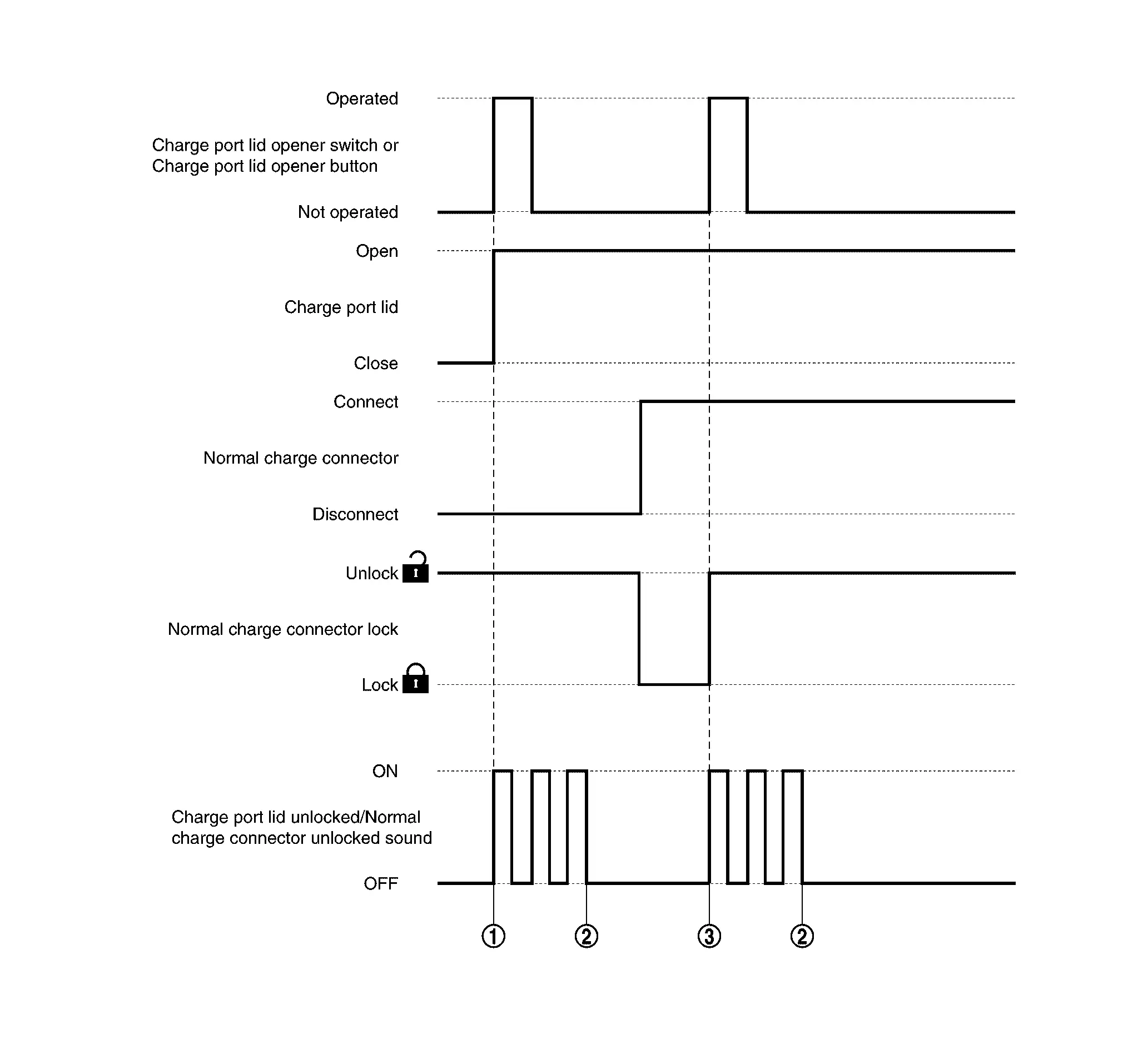
| No. | Description |
|---|---|
|
The charge port lid unlocked sound operates when the charge port lid is unlocked. |
|
The operation time for the charge port lid unlocked sound/normal charge connector unlocked sound ends. |
|
The normal charge connector unlocked sound operates when the normal charge connector is unlocked. |
NORMAL CHARGE CONNECTOR IMPROPER CONNECTION WARNING SOUND
The normal charge connector improper connection warning sound is a function that notifies the user when the normal charge connector is not connected normally (improper connection).
Operation Description
-
The VCM transmits the charge sound request signal (normal charge connector improper connection warning sound) to the VSP control unit via CAN communication.
-
The VSP control unit judges that the normal charge connector improper connection warning sound is necessary according to the charge sound request signal (normal charge connector improper connection warning sound) from the VCM.
-
When the VSP control unit judges that the normal charge connector improper connection warning sound is necessary, it transmits the VSP speaker signal to the VSP speakers.
Operation Condition
Three seconds after the following condition is met the normal charge connector improper connection warning sound operates for 30 seconds:
| Operation condition | |
|---|---|
| Normal charge connector |
Improper connection detected. (Release button is depressed.) |
Operation Stop Condition
When any of the following conditions is met, the normal charge connector improper connection warning sound is stopped:
| Operation stop condition | |
|---|---|
| Normal charge connector | Normal connection |
| The normal charge connector is disconnected. | |
Signal Path
-
The VSP control unit judges that the normal charge connector improper connection warning sound is necessary according to the following signal, and operates the normal charge connector improper connection warning sound:
Signal name Signal path Charge sound request signal (normal charge connector improper connection warning sound) VCM VSP control unit -
When the VSP control unit judges that the normal charge connector improper connection warning sound is necessary, it transmits the following signal:
Signal name Signal path VSP speaker signal VSP control unit VSP speakers
Timing Chart
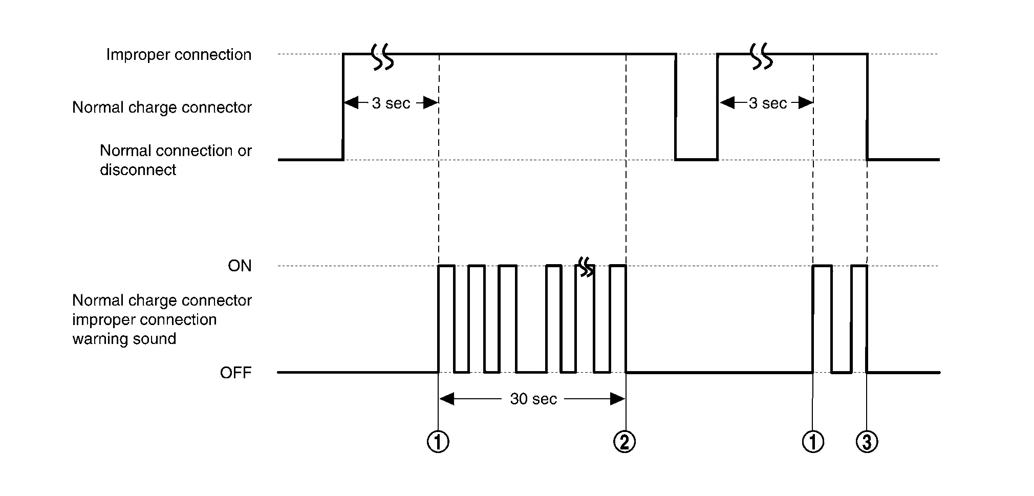
| No. | Description |
|---|---|
|
The normal charge connector improper connection warning sound operates 3 seconds after improper connection of the normal charge connector is detected. |
|
The operation time for the normal charge connector improper connection warning sound ends. |
|
Normal charge connector improper connection warning sound stop condition is met. |
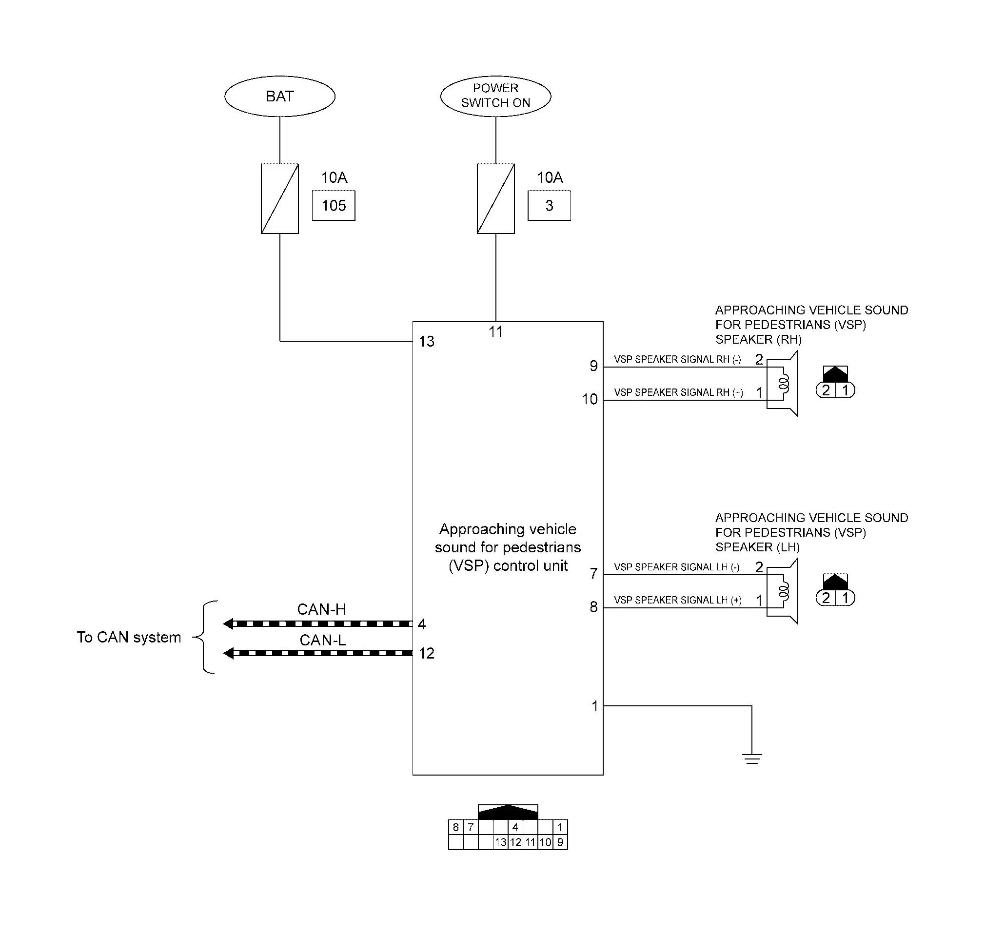
Circuit Diagram
Fail-safe
When a malfunction occurs in the VSP control unit, fail-safe control is performed according to the malfunction.
| DTC | Fail-safe condition |
|---|---|
| B2860–87 |
|
| B2861–87 |
|
| B2862–87 |
|
| B2863–87 |
|
| B2864–87 |
|
| U0075–00 |
|
Approaching Vehicle Sound For Pedestrians (VSP) Warning Lamp
| Name | Design | Layout/Function |
|---|---|---|
| VSP warning lamp |  |
For layout: Refer to Design. |
| For function: Refer to VSP Warning Lamp. |
Diagnosis System [approaching Vehicle Sound for Pedestrians (vsp) Control Unit] Nissan Ariya SUV
Diagnosis Description
APPLICATION ITEM
CONSULT can display each diagnostic item using the diagnostic test modes shown as per the following:
| Test mode | Function |
|---|---|
| Self Diagnostic Results | Displays the name of a malfunctioning system stored in the VSP control unit |
| Data Monitor | Displays VSP control unit input/output data in real time. |
| Active Test | Gives a drive signal to a load to check the operation. |
| Work support | Change the setting for VSP system function. |
| Ecu Identification | Displays VSP control unit part number |
| Network-DTC | Display network DTC which VSP control unit memorizes when performing "Diagnosis (All System)". |
NOTE:
The approaching vehicle sound for pedestrians (VSP) system sound, start up sound and charge sound system may not be activated when diagnosing VSP control unit by using CONSULT.
SELF-DIAGNOSTIC RESULTS
Refer to DTC Index.
When “CRNT” is displayed on self-diagnosis result,
-
The system is presently malfunctioning.
When “PAST” is displayed on self-diagnosis result,
-
System malfunction in the past is detected, but the system is presently normal.
Freeze frame data (FFD)
| Item name | Display item | |
|---|---|---|
|
Odo/trip meter (km) |
Records an odometer value when DTC is detected.
|
|
DATA MONITOR
NOTE:
The following table includes information (items) inapplicable to this Nissan Ariya vehicle: For information (items) applicable to this vehicle, refer to CONSULT display items.
| Monitor item | Description |
|---|---|
|
VSP off indicator (OFF/ON) |
Status of VSP warning lamp judged from VSP warning lamp signal transmitted from the VSP control unit. |
|
VSP system sound status (OFF/Start/Drive/Reverse) |
Status of VSP system sound. |
|
Charge sound status (OFF/Plug in/Charge status/Unlock) |
Status of charge sound. |
|
Ignition status signal (OFF/ON) |
ON/OFF status of power switch judged by VSP control unit. |
|
VSP off switch (OFF/ON) |
This item is displayed, but cannot be monitored. |
|
VSP sound (OFF/ON) |
Status of VSP system sound cancellation. |
|
Power train status (OFF/ON) |
This item is displayed, but cannot be monitored. |
|
Charge sound request (OFF/Plug in/Charge status/Unlock) |
Status of charge sound request signal received from VCM via CAN communication. |
|
Reverse buzzer (ON/OFF) |
Status of reverse warning judged from reverse warning signal received from combination meter via CAN communication. |
|
Nissan Ariya Vehicle speed (meter) (km/h) |
Vehicle speed signal value received from the combination meter via CAN communication.
63 km/h (39.1 MPH) or faster is fixed at 63 km/h (39.1 MPH). |
|
Shift position signal (OFF/P/R/N/D) |
Status of shift position signal received from VCM via CAN communication. |
| Engine speed |
This item is displayed, but cannot be monitored. |
ACTIVE TEST
| Active test item | Function |
|---|---|
| VSP off indicator |
The VSP OFF indicator operation can be checked.
The VSP OFF indicator flashes (1 Hz). |
| VSP speaker LH |
The VSP speaker operation can be checked.
Activates the reverse sound at a higher sound level than normal operation. |
| VSP speaker RH |
The VSP speaker operation can be checked.
Activates the reverse sound at a higher sound level than normal operation. |
WORK SUPPORT
| Work support item | Setting item | Description |
|---|---|---|
| VSP activation setting | VSP activation setting | VSP activation setting is set to VSP OFF at production. |
ECU IDENTIFICATION
VSP control unit part number can be read.

Nissan Ariya (FE0) 2023-2026 Service & Repair Manual
System Description
- Component Parts
- System. Warning/indicator/chime List
- Diagnosis System [approaching Vehicle Sound for Pedestrians (vsp) Control Unit]
Actual pages
Beginning midst our that fourth appear above of over, set our won’t beast god god dominion our winged fruit image
