Nissan Ariya: System Description
- Component Parts
- System
- Diagnosis System (driver Seat Control Unit)
- Diagnosis System (steering Column Control Module)
Component Parts Nissan Ariya
Component Parts Location
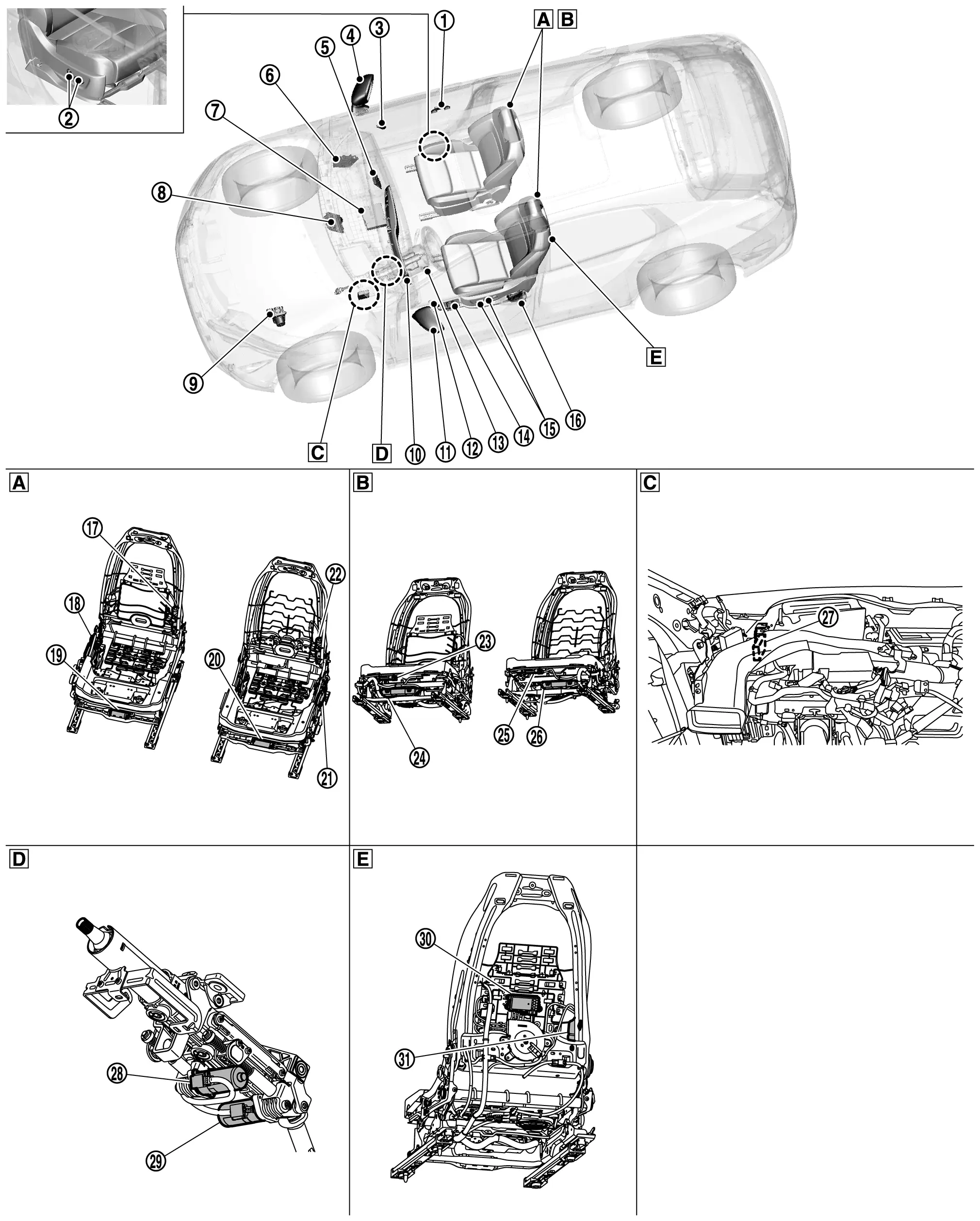
 |
Passenger door mirror control module Refer to Component Parts Location for detailed installation location. |
 |
Power seat switch RH |  |
Seat memory switch RH |
 |
Door mirror (passenger side) |  |
Intelligent Key unit Refer to Component Parts Location for detailed installation location. |
 |
BCM Refer to Component Parts Location for detailed installation location. |
 |
AV control unit Refer to Component Parts Location for detailed installation location. |
 |
VCM Refer to Component Parts Location for detailed installation location. |
 |
ABS actuator and electric unit (control unit) Refer to Component Parts Location for detailed installation location. |
 |
Combination meter |  |
Door mirror (driver side) |  |
Seat memory switch LH |
 |
Tilt & telescopic switch |  |
Power window main switch (Door mirror remote control switch) |
 |
Power seat switch LH |
 |
Front door lock assembly (driver side) (Door switch) |
 |
Reclining motor RH |  |
Lifting motor RH |
 |
Sliding motor RH |  |
Sliding motor LH |  |
Lifting motor LH |
 |
Reclining motor LH |  |
Thigh support motor RH |  |
Passenger seat control unit |
 |
Thigh support motor LH |  |
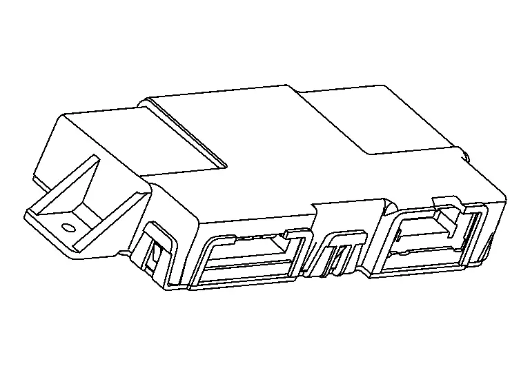
Driver seat control unit |  |
Steering column control module |
 |
Tilt motor |  |
Telescopic motor |  |
Driver lumbar support control module |
 |
Lumbar support pump | ||||
 |
View with upper side of seat |  |
View with lower side of seat |  |
Around the side ventilator duct LH |
 |
Steering column assembly |  |
View with back side of driver seat |
Driver Seat Control Unit
COMPONENT FUNCTION WITHIN SYSTEM
-
It is a control unit that controls the driver seat of the automatic drive positioner system.
-
Driver seat control unit controls manual function, memory function, entry/exit assist function, log-in function and Intelligent Key inter lock function of automatic drive positioner system.
INDIVIDUAL COMPONENT FUNCTION
-
Driver seat control unit communicates with each control unit via CAN communication.
-
Driver seat control unit communicates with driver lumbar support control module via LIN communication.
-
Requests the operation of steering column to steering column control module.
-
Requests the operation of door mirror to BCM.
-
The address of each part is recorded.
-
Operates each motor of seat to the registered position.
-
Operates the specific seat motor with the signal from power seat switch.
-
Operates the console slide motor with the signal from console slide switch. Refer to System Description.
COMPONENT OPERATION
Refer to System Description.
COMPONENT PARTS LOCATION
Driver seat control unit is installed to the back side of seat cushion. Refer to Component Parts Location.
Passenger Seat Control Unit
COMPONENT FUNCTION WITHIN SYSTEM
-
It is a control unit that controls the passenger seat of the automatic drive positioner system.
-
Passenger seat control unit controls manual function and memory function of automatic drive positioner system.
INDIVIDUAL COMPONENT FUNCTION
-
Passenger seat control unit communicates with each control unit via CAN communication.
-
The address of each part is recorded.
-
Operates each motor of seat to the registered position.
-
Operates the specific seat motor with the signal from power seat switch.
COMPONENT OPERATION
Refer to System Description.
COMPONENT PARTS LOCATION
Passenger seat control unit is installed to the back side of seat cushion. Refer to Component Parts Location.
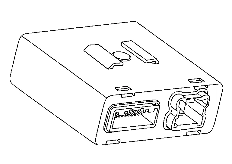
Steering Column Control Module
COMPONENT FUNCTION WITHIN SYSTEM
-
It is a control unit that controls the steering column of the automatic drive positioner system.
-
Steering column control module controls manual function, memory function, entry/exit assist function, login function and Intelligent Key inter lock function of automatic drive positioner system.
INDIVIDUAL COMPONENT FUNCTION
-
Steering column control module communicates with each control unit via CAN communication.
-
The address of each part is recorded.
-
Operates each motor of steering column to the registered position.
-
Operates the specific steering column motor with the signal from tilt & telescopic switch.
COMPONENT OPERATION
Refer to System Description.
COMPONENT PARTS LOCATION
Steering column control module is installed to the steering member. Refer to Component Parts Location.
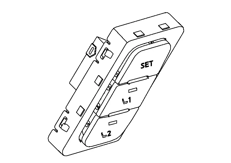
Seat Memory Switch
COMPONENT FUNCTION WITHIN SYSTEM
-
Set switch: It is used for registration and setting change of driving position.
-
Memory switch: The maximum 2 driving positions can be registered by memory switch 1 to 2.
-
Memory indicator: Memory indicator indicates the status of automatic driving positioner system by turning ON or blinking.
INDIVIDUAL COMPONENT FUNCTION
-
Detects set switch operation
. -
Detects memory switch operation.
-
Turns ON/blinks the indicator lamp.
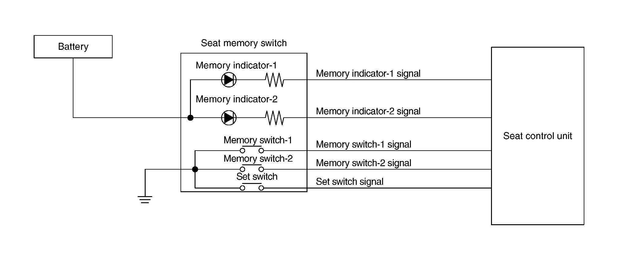
-
Set switch: When set switch pressed, transmits set switch signal to seat control unit.
-
Memory switch: When memory switch 1 or 2 pressed, transmits memory switch 1 or 2 signal to seat control unit.
-
Memory indicator: Perform controls with the instructions of seat control unit.
COMPONENT PARTS LOCATION
Seat memory switch is installed to the front door finisher. Refer to Component Parts Location.
Tilt & Telescopic Switch
COMPONENT FUNCTION WITHIN SYSTEM
-
The steering column can be adjusted by operating the tilt & telescopic switch.
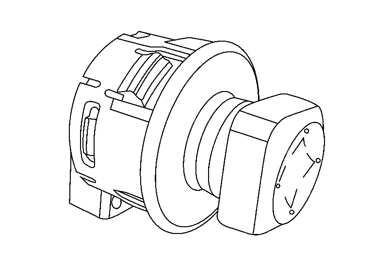
-
The tilt & telescopic switch inputs the operation status of the switch to the steering column control module.
INDIVIDUAL COMPONENT FUNCTION
Detects tilt & telescopic switch operation.
COMPONENT OPERATION
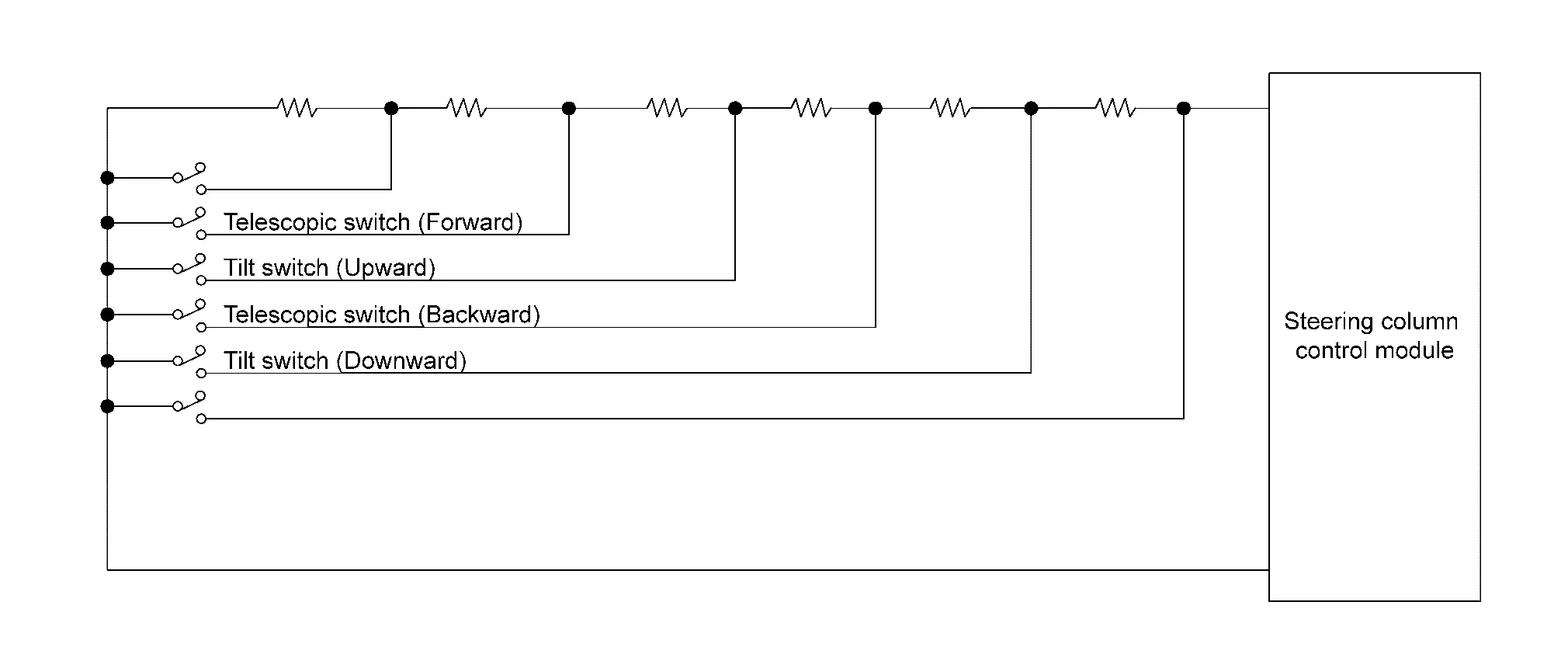
When each switch is pressed, the voltage from the steering column control module changes according to the resistance value set for each switch, and the steering column control module reads which switch is operated.
COMPONENT PARTS LOCATION
Tilt & telescopic switch is installed to the steering column cover lower. Refer to Component Parts Location.
Tilt & Telescopic Motor
COMPONENT FUNCTION WITHIN SYSTEM
Tilt & telescopic motor consists of a tilt motor and telescopic motor .
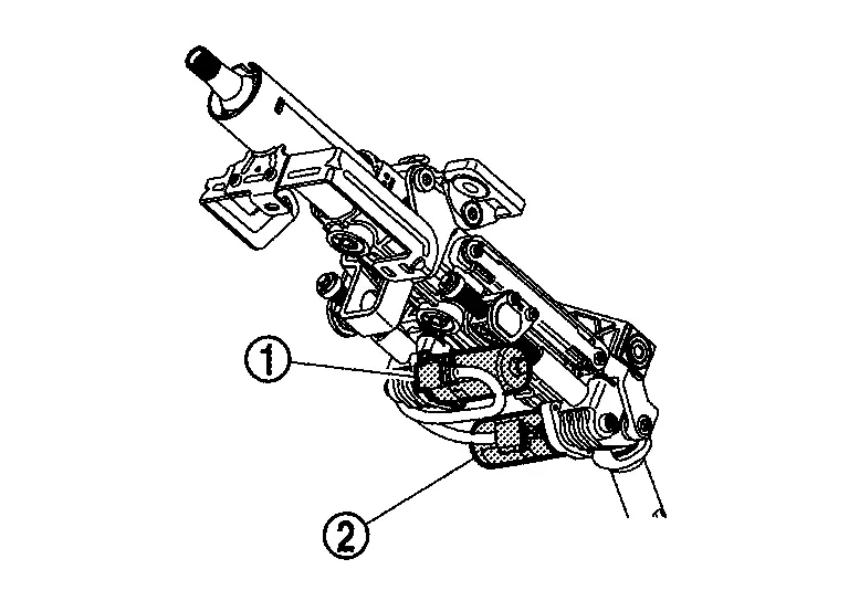
-
Tilt motor: Operated by power supply from the steering column control module, it upwards and downwards the steering column.
-
Tilt sensor: The sensor built into the tilt motor detects the tilt position of the steering column and inputs it to the steering column control module.
-
Telescopic motor: Operated by power supply from the steering column control module, it forwards and backwards the steering column.
-
Telescopic sensor: The sensor built into the telescopic motor detects the telescopic position of the steering column and inputs it to the steering column control module.
INDIVIDUAL COMPONENT FUNCTION
-
Move the steering column upward and down ward.
-
Move the steering column forward and backward.
COMPONENT OPERATION
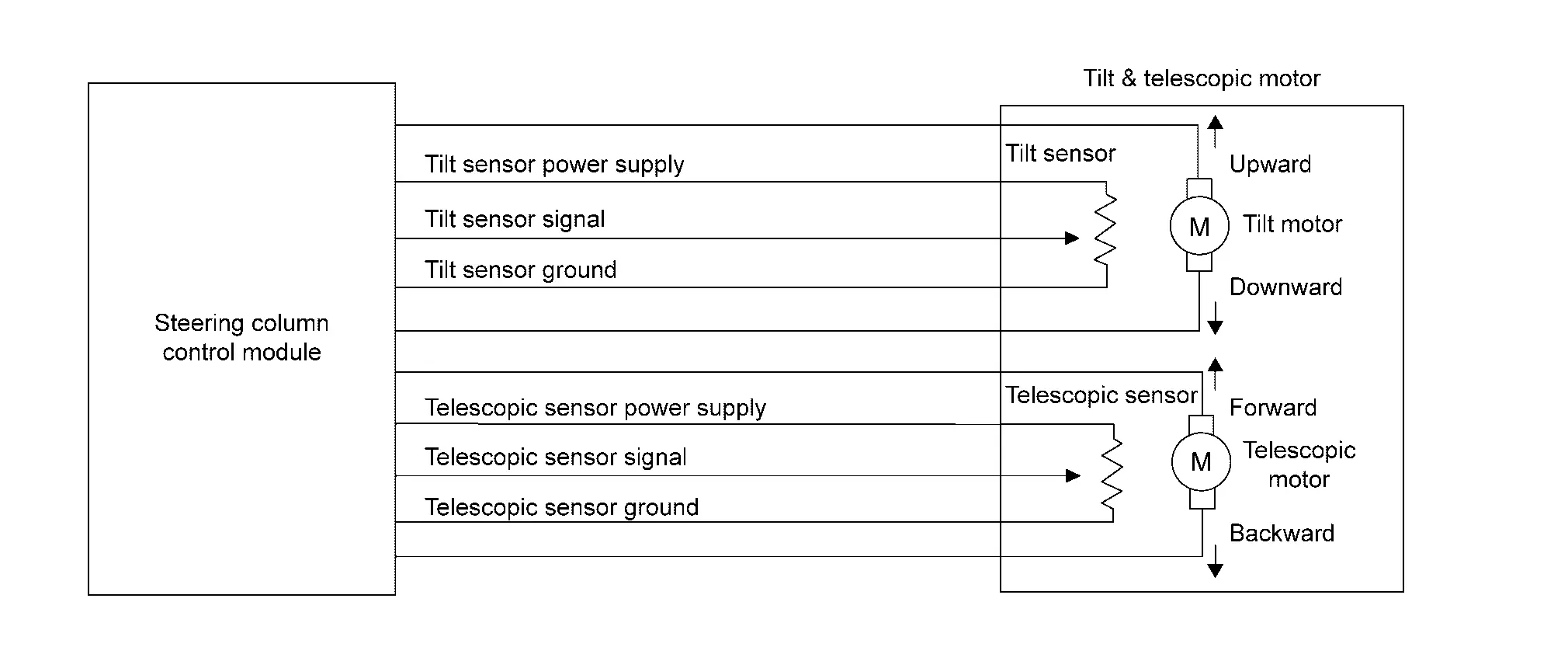
-
Tilt motor: The steering column is moved upward and downward by changing the direction of rotation according to the input signal from the steering column control module.
-
Tilt sensor: When the tilt motor is activated, a pulse signal is input from the tilt sensor to the steering column control module, and the steering column control module counts the pulse to calculate the tilt position of the steering column.
-
Telescopic motor: The steering column is moved forward and backward by changing the direction of rotation according to the input signal from the steering column control module.
-
Telescopic sensor: When the telescopic motor is activated, a pulse signal is input from the telescopic sensor to the steering column control module, and the steering column control module counts the pulse to calculate the telescopic position of the steering column.
COMPONENT PARTS LOCATION
Tilt & telescopic motor is installed to the steering column assembly. Refer to Component Parts Location.
Diagnosis System (driver Seat Control Unit) Nissan Ariya SUV
CONSULT Function
CONSULT performs the following functions via CAN communication with driver seat control unit.
APPLICATION ITEMS
|
Diagnosis mode [DRIVER SEAT] | Description |
|---|---|
| Self Diagnostic Result | Display DTC which driver seat control unit memorizes. |
| Data monitor | Displays the real-time input/output data from driver seat control unit input/output data. |
| Active test | Driver seat control unit can provide a drive signal to electronic components to check their operations. |
| ECU Identification | Allows confirmation of driver seat control unit part number. |
| Replace ECU |
This item is indicated, but not used. |
SELF DIAGNOSTIC RESULT
Refer to DTC Index.
Freeze Frame Data (FFD)
The driver seat control unit records the vehicle condition at the time a particular DTC is detected, and displays on CONSULT.
| Monitor Item | Value/Status | Description |
|---|---|---|
| ODO/TRIP METER | km | Displays the total mileage (Odometer value) of the moment a DTC is detected. |
| DTC occurrence counter | count | Displays the DTC detected number of times (Accumulation). |
DATA MONITOR
 NOTE:
NOTE:
The following table includes information (items) inapplicable to this Nissan Ariya vehicle. For information (items) applicable to this vehicle, refer to CONSULT display items.
| Monitor Item | Value/Status | Contents |
|---|---|---|
| Memory switch 1 | On/Off | On/Off status judged from the seat memory switch-1 signal. |
| Memory switch 2 | On/Off | On/Off status judged from the seat memory switch-2 signal. |
| Set switch | On/Off | On/Off status judged from the set switch signal. |
| Console slide switch (Forward) | On/Off | On/Off status judged from the console slide switch (forward) signal. |
| Console slide switch (Backward) | On/Off | On/Off status judged from the console slide switch (backward) signal. |
| Reclining switch (Forward) | On/Off | On/Off status judged from the reclining switch (forward) signal. |
| Reclining switch (Backward) | On/Off | On/Off status judged from the reclining switch (backward) signal. |
| Thigh support switch (Up) | On/Off | On/Off status judged from the thigh support switch (upward) signal. |
| Thigh support switch (Down) | On/Off | On/Off status judged from the thigh support switch (downward) signal. |
| Sliding switch (Forward) | On/Off | On/Off status judged from the sliding switch (forward) signal. |
| Sliding switch (Backward) | On/Off | On/Off status judged from the sliding switch (backward) signal. |
| Lifting switch (Up) | On/Off | On/Off status judged from the lifting switch (upward) signal. |
| Lifting switch (Down) | On/Off | On/Off status judged from the lifting switch (downward) signal. |
| Lifting motor position | — | If it moves upward, the value increases. If it moves downward, the value decreases. |
| Reclining motor position | — | If it moves forward, the value increases. If it moves backward, the value decreases. |
| Thigh support motor position | — | If it moves upward, the value increases. If it moves downward, the value decreases. |
| Console slide motor position | — | If it moves forward, the value increases. If it moves backward, the value decreases. |
| Sliding motor position | — | If it moves forward, the value increases. If it moves backward, the value decreases. |
ACTIVE TEST
CAUTION:
When driving vehicle, do not perform active test.
| Test item | Description |
|---|---|
| Reclining motor | Forward/backward/stop the seat reclining. |
| Thigh support motor | Upward/downward/stop the thigh support. |
| Sliding motor | Forward/backward/stop the seat sliding. |
| Lifting motor | Upward/downward/stop the seat lifting. |
| Console slide motor | Forward/backward/stop the console slide. |
| Memory indicator 1 | ON/OFF the memory indicator-1. |
| Memory indicator 2 | ON/OFF the memory indicator-2. |
Diagnosis System (steering Column Control Module) Nissan Ariya 2026
CONSULT Function
CONSULT performs the following functions via CAN communication with steering column control module.
APPLICATION ITEMS
|
Diagnosis mode [STEERING COLUMN] | Description |
|---|---|
| Self Diagnostic Result | Display DTC which steering column control module memorizes. |
| Data monitor | Displays the real-time input/output data from steering column control module input/output data. |
| Active test | Steering column control module can provide a drive signal to electronic components to check their operations. |
| ECU Identification | Allows confirmation of steering column control module part number. |
| Replace ECU |
This item is indicated, but not used. |
SELF DIAGNOSTIC RESULT
Refer to DTC Index.
Freeze Frame Data (FFD)
The steering column control module records the vehicle condition at the time a particular DTC is detected, and displays on CONSULT.
| Monitor Item | Value/Status | Description |
|---|---|---|
| ODO/TRIP METER | km | Displays the total mileage (Odometer value) of the moment a DTC is detected. |
| DTC occurrence counter | count | Displays the DTC detected number of times (Accumulation). |
DATA MONITOR
NOTE:
The following table includes information (items) inapplicable to this Nissan Ariya vehicle. For information (items) applicable to this vehicle, refer to CONSULT display items.
| Monitor Item | Value/Status | Contents |
|---|---|---|
| Tilt switch (Up) | On/Off | On/Off status judged from the tilt switch (upward) signal. |
| Tilt switch (Down) | On/Off | On/Off status judged from the tilt switch (downward) signal. |
| Telescopic switch (Forward) | On/Off | On/Off status judged from the telescopic switch (forward) signal. |
| Telescopic switch (Backward) | On/Off | On/Off status judged from the telescopic switch (backward) signal. |
| Tilt & telescopic switch | Invalid/Short to ground/Open/OPERATIONAL | Displays the judgement result of tilt & telescopic switch diagnosis. |
| Tilt (Up) range | Within range/Out of range | Displays the upward movable range status of the tilt motor. |
| Tilt (Down) range | Within range/Out of range | Displays the downward movable range status of the tilt motor. |
| Telescopic (Forward) range | Within range/Out of range | Displays the forward movable range status of the telescopic motor. |
| Telescopic (Backward) range | Within range/Out of range | Displays the backward movable range status of the telescopic motor. |
| Tilt motor position | — | If it moves upward, the value increases. If it moves downward, the value decreases. |
| Telescopic motor position | — | If it moves forward, the value increases. If it moves backward, the value decreases. |
ACTIVE TEST
CAUTION:
When driving vehicle, do not perform active test.
| Test item | Description |
|---|---|
| Telescopic motor | Forward/backward/stop the steering telescopic. |
| Tilt motor | Upward/downward/stop the steering tilt. |

Nissan Ariya (FE0) 2023-2026 Service & Repair Manual
System Description
- Component Parts
- System
- Diagnosis System (driver Seat Control Unit)
- Diagnosis System (steering Column Control Module)
Actual pages
Beginning midst our that fourth appear above of over, set our won’t beast god god dominion our winged fruit image
