Nissan Ariya: Dtc/circuit Diagnosis
- B2c95-01 Combination Switch
- B2c95-64 Combination Switch
- U0073-00 Can Comm Circuit
- U1327-52 Mac Key
- U1327-54 Mac Key
- U1c00-08 Lin Communication
- U1c01-08 Lin Communication
- U1c02-08 Lin Communication
- U1c03-08 Lin Communication
- U2143-57 Mac Comm Error (vcm)
- Power Supply and Ground Circuit
- Combination Switch Input Circuit
- Combination Switch Output Circuit
B2c95-01 Combination Switch Nissan Ariya first Gen
DTC Description
DTC DETECTION LOGIC
| DTC No. | CONSULT screen items | DTC Detection Condition | |
|---|---|---|---|
| B2C95-01 | Combination switch | Diagnosis condition | Power switch OFF (auto ACC status) |
| Signal (terminal) | Combination switch signal | ||
| Threshold | Combination switch circuit short to battery | ||
| Diagnosis delay time | 2 seconds or more | ||
POSSIBLE CAUSE
-
Harness or connector (Combination switch circuit is short to battery)
-
Combination switch
-
BCM
FAIL-SAFE
Turns ON the headlamp (LO)
DTC CONFIRMATION PROCEDURE
CHECK SELF-DIAG RESULT
 With CONSULT
-
Erase DTC.
-
Power switch OFF.
-
Perform the “Self Diagnostic Result” of BCM with CONSULT, when passed 2 seconds or more after the power switch is turned OFF (auto ACC status).
Is DTC detected?
YES>>Refer to Diagnosis Procedure.
NO-1>>To check malfunction symptom before repair: Refer to Intermittent Incident.
NO-2>>Confirmation after repair: INSPECTION END
Diagnosis Procedure
CHECK COMBINATION SWITCH CIRCUIT FOR SHORT TO BATTERY
-
Power switch OFF.
-
Disconnect combination switch connector and BCM connectors.
-
Check voltage between combination switch harness connector and ground.
+ - Voltage
(Approx.)Combination switch Connector Terminal M32 1 Ground 0 V 2 3 4 5 6 7 8 10 12 13 15
Is the inspection result normal?
YES>>GO TO 2.
NO>>Repair or replace harness or connectors.
PERFORM “DATA MONITOR” OF BCM (COMB SW)
With CONSULT
-
Connect combination switch connector and BCM connectors.
-
Perform “Data Monitor” of BCM (COMB SW) to check for any malfunctioning item. Refer to Symptom Table.
Is the inspection result normal?
YES>>Replace combination switch. Refer to Removal and Installation.
NO>>Replace BCM. Refer to Removal and Installation.
B2c95-64 Combination Switch Nissan Ariya 2023
DTC Description
DTC DETECTION LOGIC
| DTC No. | CONSULT screen items | DTC Detection Condition | |
|---|---|---|---|
| B2C95-64 | Combination switch | Diagnosis condition | Power switch OFF (auto ACC status) |
| Signal (terminal) | Combination switch signal | ||
| Threshold | BCM detects the combination switch check diode positions stuck at ON for 2 seconds or more | ||
| Diagnosis delay time | 2 seconds or more | ||
POSSIBLE CAUSE
-
Harness or connector (Combination switch circuit is short to battery)
-
Combination switch
-
BCM
FAIL-SAFE
Turns ON the headlamp (LO)
DTC CONFIRMATION PROCEDURE
CHECK SELF-DIAG RESULT
With CONSULT
-
Erase DTC.
-
Power switch OFF.
-
Perform the “Self Diagnostic Result” of BCM with CONSULT, when passed 2 seconds or more after the power switch is turned OFF (auto ACC status).
Is DTC detected?
YES>>Refer to Diagnosis Procedure.
NO-1>>To check malfunction symptom before repair: Refer to Intermittent Incident.
NO-2>>Confirmation after repair: INSPECTION END
Diagnosis Procedure
CHECK COMBINATION SWITCH SYSTEM SYMPTOMS
Perform COMBINATION SWITCH SYSTEM SYMPTOMS. Refer to Symptom Table.
>>
INSPECTION END
U0073-00 Can Comm Circuit Nissan Ariya first Gen
DTC Description
DESCRIPTION
CAN (Controller Area Network) is a serial communication line for real time applications. It is an on-Nissan Ariya vehicle multiplex communication line with high data communication speed and excellent error detection ability. Modern Nissan Ariya vehicle is equipped with many electronic control unit, and each control unit shares information and links with other control units during operation (not independent). In CAN communication, control units are connected with 2 communication lines (CAN H-line, CAN L-line) allowing a high rate of information transmission with less wiring. Each control unit transmits/receives data but selectively reads required data only. CAN Communication Signal Chart. Refer to CAN Communication Signal Chart.
DTC DETECTION LOGIC
| DTC No. | CONSULT screen items | DTC Detection Condition | |
|---|---|---|---|
| U0073-00 | Control module communication Bus A Off | Diagnosis condition | Power switch is ON. |
| Signal (terminal) | CAN communication signal | ||
| Threshold | Transmission error or reception error | ||
| Diagnosis delay time | 2 seconds or more | ||
POSSIBLE CAUSE
CAN communication system
FAIL-SAFE
—
DTC CONFIRMATION PROCEDURE
CHECK SELF-DIAG RESULT
With CONSULT
-
Power switch ON and wait for 2 seconds or more.
-
Perform “Self Diagnostic Result” mode of “BCM” using CONSULT.
Is DTC detected?
YES>>Refer to Diagnosis Procedure.
NO-1>>To check malfunction symptom before repair: Refer to Intermittent Incident.
NO-2>>Confirmation after repair: INSPECTION END
Diagnosis Procedure
CHECK CAN COMMUNICATION SYSTEM
Check CAN communication system. Refer to Trouble Diagnosis Flow Chart.
>>
INSPECTION END
U1327-52 Mac Key Nissan Ariya: FE0
DTC Description
DTC DETECTION LOGIC
| DTC No. | CONSULT screen items | DTC Detection Condition | |
|---|---|---|---|
| U1327-52 | MAC key update | Diagnosis condition | - |
| Signal (terminal) | - | ||
| Threshold | MAC key writing is incomplete. | ||
| Diagnosis delay time | - | ||
POSSIBLE CAUSE
-
Network communication error between CONSULT and BCM
-
BCM used in other vehicles is installed in the Nissan Ariya vehicle
-
BCM
FAIL-SAFE
—
DTC CONFIRMATION PROCEDURE
CHECK DTC PRIORITY
If DTC U1327-52 is displayed with DTC U1327-54, first perform the trouble diagnosis for DTC U1327-54.
Is DTC U1327-54 detected?
YES>>Refer to DTC Description.
NO>>GO TO 2.
PERFORM DTC CONFIRMATION PROCEDURE
With CONSULT
-
Ignition switch ON.
-
Perform “MAC key writing”. Refer to Description.
-
Perform “MAC Diagnosis” of “BCM” using CONSULT.
Is DTC U1327-52 detected as the current malfunction?
YES>>Refer to Diagnosis Procedure.
NO-1>>To check malfunction symptom before repair: Refer to Intermittent Incident.
NO-2>>Confirmation after repair: INSPECTION END
Diagnosis Procedure
CHECK DTC PRIORITY
If DTC U1327-52 is displayed with DTC U1327-54, first perform the trouble diagnosis for DTC U1327-54.
Is DTC U1327-54 detected?
YES>>Refer to DTC Description.
NO>>GO TO 2.
PERFORM MAC KEY WRITING
With CONSULT
-
Perform “MAC key writing”. Refer to Description.
-
Perform “MAC Diagnosis” of “BCM” using CONSULT.
Is DTC U1327-52 detected as the current malfunction?
YES>>GO TO 3.
NO>>INSPECTION END.
REPLACE BCM
Replace BCM. Refer to Removal and Installation.
>>
INSPECTION END
U1327-54 Mac Key Nissan Ariya SUV
DTC Description
DTC DETECTION LOGIC
| DTC No. | CONSULT screen items | DTC Detection Condition | |
|---|---|---|---|
| U1327-54 | MAC key update | Diagnosis condition | - |
| Signal (terminal) | - | ||
| Threshold | MAC key is not written after BCM replacement. | ||
| Diagnosis delay time | - | ||
POSSIBLE CAUSE
-
Writing of MAC key has not been executed
-
BCM
FAIL-SAFE
-
DTC CONFIRMATION PROCEDURE
PERFORM DTC CONFIRMATION PROCEDURE
With CONSULT
-
Power switch ON.
-
Perform “MAC Diagnosis” of “BCM” using CONSULT.
Is DTC U1327-54 detected as the current malfunction?
YES>>Refer to Diagnosis Procedure.
NO-1>>To check malfunction symptom before repair: Refer to Intermittent Incident.
NO-2>>Confirmation after repair: INSPECTION END
Diagnosis Procedure
PERFORM MAC KEY WRITING
With CONSULT
-
Perform “MAC key writing”. Refer to Description.
-
Perform “MAC Diagnosis” of “BCM” using CONSULT.
Is DTC U1327-54 detected as the current malfunction?
YES>>GO TO 2.
NO>>INSPECTION END
PERFORM MAC KEY WRITING AGAIN (SECOND TIMES)
With CONSULT
-
Restart CONSULT.
-
Perform “MAC Key writing” again. Refer to Description.
-
Perform “MAC Diagnosis” of “BCM” using CONSULT.
Is DTC U1327-54 detected as the current malfunction?
YES>>GO TO 3.
NO>>INSPECTION END
PERFORM MAC KEY WRITING AGAIN (THIRD TIMES)
With CONSULT
-
Restart CONSULT.
-
Perform “MAC Key writing” again. Refer to Description.
-
Perform “MAC Diagnosis” of “BCM” using CONSULT.
Is DTC U1327-54 detected as the current malfunction?
YES>>Replace BCM. Refer to Removal and Installation.
NO>>INSPECTION END
U1c00-08 Lin Communication Nissan Ariya 2023
DTC Description
 NOTE:
NOTE:
When the power switch is turned ON, the DTC may be detected. If it has been detected due to previous error/operation, erase the history once and check if the DTC is detected again.
DTC DETECTION LOGIC
| DTC No. | CONSULT screen terms | DTC detection condition | |
|---|---|---|---|
| U1C00-08 | LIN communication | Diagnosis condition | Power switch OFF (auto ACC status) or ON |
| Signal (terminal) | LIN communication signal | ||
| Threshold | BCM detects LIN communication error. | ||
| Diagnosis delay time | 1 second or less | ||
POSSIBLE CAUSE
-
Harness or connector (The light & rain sensor circuit is open or shorted)
-
Light & rain sensor
-
BCM
FAIL-SAFE
—
DTC CONFIRMATION PROCEDURE
CHECK SELF-DIAG RESULT
With CONSULT
-
Power switch ON.
-
Select “Self Diagnostic Result” mode of “BCM” using CONSULT.
Is DTC detected?
YES>>Refer to Diagnosis Procedure.
NO-1>>To check malfunction symptom before repair: Refer to Intermittent Incident.
NO-2>>Confirmation after repair: INSPECTION END
Diagnosis Procedure
CHECK LIN COMMUNICATION CIRCUIT
Check LIN communication circuit. Refer to Diagnosis Procedure.
>>
INSPECTION END
U1c01-08 Lin Communication Nissan Ariya
DTC Description
NOTE:
When the power switch is turned ON, the DTC may be detected. If it has been detected due to previous error/operation, erase the history once and check if the DTC is detected again.
DTC DETECTION LOGIC
| DTC No. | CONSULT screen items | DTC Detection Condition | |
|---|---|---|---|
| U1C01-08 | LIN communication | Diagnosis condition | Power switch is ON or OFF (auto ACC status). |
| Signal (terminal) | LIN communication signal | ||
| Threshold | BCM detects LIN communication error. | ||
| Diagnosis delay time | 1 second or less | ||
POSSIBLE CAUSE
-
LIN communication line
-
Hands free sensor control unit
-
BCM
FAIL-SAFE
—
DTC CONFIRMATION PROCEDURE
CHECK SELF-DIAG RESULT
With CONSULT
-
Power switch ON.
-
Perform “Self Diagnostic Result” mode of “BCM” using CONSULT.
Is DTC detected?
YES-1>>CRNT: Refer to Diagnosis Procedure.
YES-2>>PAST: GO TO 2.
NO-1>>To check malfunction symptom before repair: Refer to Intermittent Incident.
NO-2>>Confirmation after repair: INSPECTION END
CHECK OPERATION
Check the automatic back door system (hands free function) operate properly.
Is the inspection result normal?
YES>>INSPECTION END
NO>>Refer to Diagnosis Procedure.
Diagnosis Procedure
CHECK HANDS FREE SENSOR CONTROL UNIT POWER SUPPLY AND GROUND CIRCUIT
Check hands free sensor control unit power supply and ground circuit.
Refer to Diagnosis Procedure.
Is the inspection result normal?
YES>>GO TO 2.
NO>>Repair or replace harness.
CHECK AUTOMATIC BACK DOOR SERIAL COMMUNICATION
Check automatic back door serial communication.
Refer to Diagnosis Procedure.
Is the inspection result normal?
YES>>Replace hands free sensor control unit. Refer to Removal & Installation.
NO>>Repair or replace harness.
U1c02-08 Lin Communication Nissan Ariya 1st generation
DTC Description
NOTE:
When the power switch is turned ON, the DTC may be detected. If it has been detected due to previous error/operation, erase the history once and check if the DTC is detected again.
DTC DETECTION LOGIC
| DTC No. | CONSULT screen items | DTC Detection Condition | |
|---|---|---|---|
| U1C02-08 | LIN communication | Diagnosis condition | Power switch is ON or OFF (auto ACC status). |
| Signal (terminal) | LIN communication signal | ||
| Threshold | BCM detects LIN communication error. | ||
| Diagnosis delay time | 1 second or less | ||
POSSIBLE CAUSE
-
LIN communication line
-
Power window main switch
-
Front power window motor (driver side)
-
Front power window motor (passenger side)
-
Rear power window motor RH
-
Rear power window motor LH
-
Sunroof motor assembly
-
Sunshade motor assembly
-
Passenger door mirror control module
-
BCM
FAIL-SAFE
—
DTC CONFIRMATION PROCEDURE
CHECK DTC PRIORITY 1
If DTC "U1C02-08" is displayed with following DTC, first perform the trouble diagnosis for following DTC.
-
B2C40-04
-
B2C41-04
-
B2C42-04
-
B2C43-04
-
B2C44-04
-
B2F98-04
-
B2F99-04
-
B2CCF-04
Is applicable DTC detected?
YES-1>>B2C40-04: Refer to DTC Description.
YES-2>>B2C41-04: Refer to DTC Description.
YES-3>>B2C42-04: Refer to DTC Description.
YES-4>>B2C43-04: Refer to DTC Description.
YES-5>>B2C44-04: Refer to DTC Description.
YES-6>>B2F98-04: Refer to DTC Description.
YES-7>>B2F99-04: Refer to DTC Description.
YES-8>>B2CCF-04: Refer to DTC Description.
NO>>GO TO 2.
CHECK DTC PRIORITY 2
If DTC "U1C02-08" is displayed with following DTC, first perform the trouble diagnosis for following DTC.
-
B2C40-95
-
B2C41-95
-
B2C42-95
-
B2C43-95
-
B2C44-95
-
B2F98-95
-
B2F99-95
-
B2CCF-95
Is applicable DTC detected?
YES-1>>B2C40-95: Refer to DTC Description.
YES-2>>B2C41-95: Refer to DTC Description.
YES-3>>B2C42-95: Refer to DTC Description.
YES-4>>B2C43-95: Refer to DTC Description.
YES-5>>B2C44-95: Refer to DTC Description.
YES-6>>B2F98-95: Refer to DTC Description.
YES-7>>B2F99-95: Refer to DTC Description.
YES-8>>B2CCF-95: Refer to DTC Description.
NO>>GO TO 3.
CHECK SELF-DIAG RESULT
With CONSULT
-
Power switch ON.
-
Perform “Self Diagnostic Result” mode of “BCM” using CONSULT.
Is DTC detected?
YES-1>>CRNT: Refer to Diagnosis Procedure.
YES-2>>PAST: GO TO 4.
NO-1>>To check malfunction symptom before repair: Refer to Intermittent Incident.
NO-2>>Confirmation after repair: INSPECTION END
CHECK OPERATION
Check that following systems operate properly.
-
Power window
-
Sunroof
-
Sunshade
-
Passenger door mirror
Is the inspection result normal?
YES>>INSPECTION END
NO>>Refer to Diagnosis Procedure.
Diagnosis Procedure
CHECK DTC PRIORITY 1
If DTC "U1C02-08" is displayed with following DTC, first perform the trouble diagnosis for following DTC.
-
B2C40-04
-
B2C41-04
-
B2C42-04
-
B2C43-04
-
B2C44-04
-
B2F98-04
-
B2F99-04
-
B2CCF-04
Is applicable DTC detected?
YES-1>>B2C40-04: Refer to DTC Description.
YES-2>>B2C41-04: Refer to DTC Description.
YES-3>>B2C42-04: Refer to DTC Description.
YES-4>>B2C43-04: Refer to DTC Description.
YES-5>>B2C44-04: Refer to DTC Description.
YES-6>>B2F98-04: Refer to DTC Description.
YES-7>>B2F99-04: Refer to DTC Description.
YES-8>>B2CCF-04: Refer to DTC Description.
NO>>GO TO 2.
CHECK DTC PRIORITY 2
If DTC "U1C02-08" is displayed with following DTC, first perform the trouble diagnosis for following DTC.
-
B2C40-95
-
B2C41-95
-
B2C42-95
-
B2C43-95
-
B2C44-95
-
B2F98-95
-
B2F99-95
-
B2CCF-95
Is applicable DTC detected?
YES-1>>B2C40-95: Refer to DTC Description.
YES-2>>B2C41-95: Refer to DTC Description.
YES-3>>B2C42-95: Refer to DTC Description.
YES-4>>B2C43-95: Refer to DTC Description.
YES-5>>B2C44-95: Refer to DTC Description.
YES-6>>B2F98-95: Refer to DTC Description.
YES-7>>B2F99-95: Refer to DTC Description.
YES-8>>B2CCF-95: Refer to DTC Description.
NO>>GO TO 3.
CHECK POWER WINDOW OPERATION
Check power window operation using power window main switch.
Is the inspection result normal?
YES>>GO TO 14.
NO-1>>Not operate (all power window) :GO TO 4.
NO-2>>Not operate (driver side) : GO TO 6.
NO-3>>Not operate (passenger side) : GO TO 8.
NO-4>>Not operate (rear RH) : GO TO 10.
NO-5>>Not operate (rear LH) : GO TO 12.
CHECK POWER WINDOW MAIN SWITCH POWER SUPPLY AND GROUND CIRCUIT
Check power window main switch power supply and ground circuit. Refer to Diagnosis Procedure.
Is the inspection result normal?
YES>>GO TO 5.
NO>>Repair or replace the malfunctioning parts.
CHECK LIN COMMUNICATION CIRCUIT (POWER WINDOW MAIN SWITCH)
Check LIN communication circuit. Refer to Diagnosis Procedure.
Is the inspection result normal?
YES>>Replace power window main switch. Refer to Removal and Installation.
NO>>Repair or replace the malfunctioning parts.
CHECK FRONT POWER WINDOW MOTOR (DRIVER SIDE) POWER SUPPLY AND GROUND CIRCUIT
Check front power window motor (driver side) power supply and ground circuit. Refer to Diagnosis Procedure.
Is the inspection result normal?
YES>>GO TO 7.
NO>>Repair or replace the malfunctioning parts.
CHECK LIN COMMUNICATION CIRCUIT [FRONT POWER WINDOW MOTOR (DRIVER SIDE)]
Check LIN communication circuit. Refer to Diagnosis Procedure.
Is the inspection result normal?
YES>>Replace front power window motor (driver side). Refer to Disassembly & Assembly.
NO>>Repair or replace the malfunctioning parts.
CHECK FRONT POWER WINDOW MOTOR (PASSENGER SIDE) POWER SUPPLY AND GROUND CIRCUIT
Check front power window motor (passenger side) power supply and ground circuit. Refer to Diagnosis Procedure.
Is the inspection result normal?
YES>>GO TO 9.
NO>>Repair or replace the malfunctioning parts.
CHECK LIN COMMUNICATION CIRCUIT [FRONT POWER WINDOW MOTOR (PASSENGER SIDE)]
Check LIN communication circuit. Refer to Diagnosis Procedure.
Is the inspection result normal?
YES>>Replace front power window motor (passenger side). Refer to Disassembly & Assembly.
NO>>Repair or replace the malfunctioning parts.
CHECK REAR POWER WINDOW MOTOR RH POWER SUPPLY AND GROUND CIRCUIT
Check rear power window motor RH power supply and ground circuit. Refer to Diagnosis Procedure.
Is the inspection result normal?
YES>>GO TO 11.
NO>>Repair or replace the malfunctioning parts.
CHECK LIN COMMUNICATION CIRCUIT (REAR POWER WINDOW MOTOR RH)
Check LIN communication circuit. Refer to Diagnosis Procedure.
Is the inspection result normal?
YES>>Replace rear power window motor RH. Refer to Disassembly & Assembly.
NO>>Repair or replace the malfunctioning parts.
CHECK REAR POWER WINDOW MOTOR LH POWER SUPPLY AND GROUND CIRCUIT
Check rear power window motor LH power supply and ground circuit. Refer to Diagnosis Procedure.
Is the inspection result normal?
YES>>GO TO 13.
NO>>Repair or replace the malfunctioning parts.
CHECK LIN COMMUNICATION CIRCUIT (REAR POWER WINDOW MOTOR LH)
Check LIN communication circuit. Refer to Diagnosis Procedure.
Is the inspection result normal?
YES>>Replace rear power window motor LH. Refer to Disassembly & Assembly.
NO>>Repair or replace the malfunctioning parts.
CHECK Nissan Ariya Vehicle SPECIFICATION
Check if vehicle equipped sunroof and sunshade.
Is equipped sunroof and sunshade?
YES>>GO TO 15.
NO>>GO TO 21.
CHECK SUNROOF AND SUNSHADE OPERATION
Check sunroof and sunshade operation.
Is the inspection result normal?
YES>>GO TO 21.
NO-1>>Not operate (sunroof and sunshade) : GO TO 16.
NO-2>>Not operate (sunroof) : GO TO 17.
NO-3>>Not operate (sunshade) : GO TO 19.
CHECK OPEN/CLOSED STATE THE SUNROOF AND SUNSHADE
Check open/closed state of the sunroof and sunshade.
Which is the state of sunroof and sunshade?
The sunroof and sunshade fully open>>GO TO 17.
The sunroof and sunshade fully closed>>GO TO 19.
CHECK SUNROOF MOTOR ASSEMBLY POWER SUPPLY AND GROUND CIRCUIT
Check sunroof motor assembly power supply and ground circuit. Refer to Diagnosis Procedure.
Is the inspection result normal?
YES>>GO TO 18.
NO>>Repair or replace the malfunctioning parts.
CHECK LIN COMMUNICATION CIRCUIT (SUNROOF MOTOR ASSEMBLY)
Check LIN communication circuit. Refer to Diagnosis Procedure.
Is the inspection result normal?
YES>>Replace sunroof motor assembly. Refer to Removal & Installation.
NO>>Repair or replace the malfunctioning parts.
CHECK SUNSHADE MOTOR ASSEMBLY POWER SUPPLY GROUND CIRCUIT
Check sunshade motor assembly power supply and ground circuit. Refer to Diagnosis Procedure.
Is the inspection result normal?
YES>>GO TO 20.
NO>>Repair or replace the malfunctioning parts.
CHECK LIN COMMUNICATION CIRCUIT (SUNSHADE MOTOR ASSEMBLY)
Check LIN communication circuit. Refer to Diagnosis Procedure.
Is the inspection result normal?
YES>>Replace sunshade motor assembly. Refer to Removal & Installation.
NO>>Repair or replace the malfunctioning parts.
CHECK Nissan Ariya Vehicle SPECIFICATION
Check if vehicle equipped automatic drive positioner.
Is equipped automatic drive positioner?
YES>>GO TO 21.
NO>>INSPECTION END
CHECK PASSENGER DOOR MIRROR OPERATION
Check passenger door mirror operation.
Is the inspection result normal?
YES>>INSPECTION END
NO>>GO TO 23.
CHECK PASSENGER DOOR MIRROR CONTROL MODULE CIRCUIT
Check passenger door mirror control module circuit. Refer to Diagnosis Procedure.
Is the inspection result normal?
YES>>Replace passenger door mirror control module. Refer to Removal & Installation.
NO>>Repair or replace the malfunctioning parts.
U1c03-08 Lin Communication Nissan Ariya SUV
DTC Description
NOTE:
When the power switch is turned ON, the DTC may be detected. If it has been detected due to previous error/operation, erase the history once and check if the DTC is detected again.
DTC DETECTION LOGIC
| DTC No. | CONSULT screen terms | DTC detection condition | |
|---|---|---|---|
| U1C03-08 | LIN communication | Diagnosis condition | Power switch OFF (auto ACC status) or ON |
| Signal (terminal) | LIN communication signal | ||
| Threshold | BCM detects LIN communication error. | ||
| Diagnosis delay time | 1 second or less | ||
POSSIBLE CAUSE
-
LIN communication line
-
Advanced ambient light (front door)
-
Advanced ambient light (instrument upper)
-
BCM
FAIL-SAFE
—
DTC CONFIRMATION PROCEDURE
CHECK SELF-DIAG RESULT
With CONSULT
-
Power switch ON.
-
Select “Self Diagnostic Result” mode of “BCM” using CONSULT.
Is DTC detected?
YES>>Refer to Diagnosis Procedure.
NO-1>>To check malfunction symptom before repair: Refer to Intermittent Incident.
NO-2>>Confirmation after repair: INSPECTION END
Diagnosis Procedure
CHECK SELF-DIAGNOSIS RESULT
With CONSULT
-
Power switch ON.
-
Select “Self Diagnostic Result” mode of “BCM” using CONSULT.
Are the DTC B2C76-04, B2C77-04, B2C78-04 and B2C79-04 detecting?
YES-1>>All of the above DTCs are detected.: GO TO 2.
YES-2>>Any of the above DTCs is detected.: Perform diagnosis of the corresponding DTC. Refer to DTC Index.
NO>>All of the above DTCs are not detected.: Replace BCM. Refer to Removal and Installation.
CHECK INTERIOR ROOM LAMP POWER SUPPLY CIRCUIT
Check interior room lamp power supply circuit. Refer to Diagnosis Procedure.
Is the inspection result normal?
YES>>GO TO 3.
NO>>Repair or replace malfunctioning parts.
CHECK ADVANCED AMBIENT LIGHT POWER SUPPLY CIRCUIT
-
Power switch OFF.
-
Disconnect following connectors.
-
Fuse block (J/B)
-
Advanced ambient light (front door LH)
-
Advanced ambient light (front door RH)
-
Advanced ambient light (instrument upper LH)
-
Advanced ambient light (instrument upper RH)
-
-
Check continuity between fuse block (J/B) harness connector and each advanced ambient light harness connector.
Front door Fuse block (J/B) Advanced ambient light (front door) Continuity Connector Terminal Connector Terminal RH M74 93 D11 1 Existed LH D51 Instrument upper Fuse block (J/B) Advanced ambient light (instrument upper) Continuity Connector Terminal Connector Terminal RH M74 93 M77 1 Existed LH M76
Is the inspection result normal?
YES>>GO TO 4.
NO>>Repair or replace harness.
CHECK LIN COMMUNICATION SIGNAL
-
Connect fuse block (J/B) connector.
-
Power switch ON.
-
Check output waveform between BCM harness connector and ground using oscilloscope.
+ - Output waveform BCM Connector Terminal M8 3 Ground 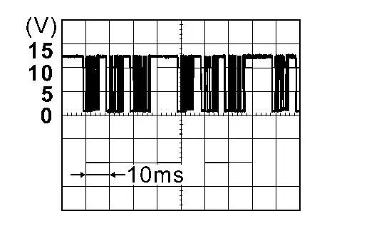
Is the inspection result normal?
YES>>GO TO 5.
NO>>Replace BCM. Refer to Removal and Installation.
CHECK LIN COMMUNICATION SIGNAL CIRCUIT
-
Power switch OFF.
-
Disconnect BCM connector.
-
Check continuity between BCM harness connector and ground.
BCM — Continuity Connector Terminal M8 3 Ground Not existed
Is the inspection result normal?
YES>>GO TO 6.
NO>>Repair or replace harness.
CHECK LIN COMMUNICATION LINE (ADVANCED AMBIENT LIGHT)
With CONSULT
-
Connect following connectors.
-
BCM
-
Advanced ambient light (front door LH)
-
Advanced ambient light (front door RH)
-
Advanced ambient light (instrument upper LH)
-
Advanced ambient light (instrument upper RH)
-
-
Power switch ON.
-
Select “Self Diagnostic Result” mode of “BCM” using CONSULT.
-
Confirm DTC detection state when each advanced ambient light connector is disconnected.
CAUTION:
The advanced ambient light connector removed for diagnosis should be reconnected after diagnosis and diagnose another part.
When the advanced ambient light (front door LH) is removed. DTC detection state Diagnosis result Detecting DTC B2C76-04, B2C77-04 or B2C78-04. A Not detecting DTC B2C76-04, B2C77-04 or B2C78-04. B When the advanced ambient light (front door RH) is removed. DTC detection state Diagnosis result Detecting DTC B2C76-04, B2C77-04 or B2C79-04. A Not detecting DTC B2C76-04, B2C77-04 or B2C79-04. C When the advanced ambient light (instrument upper LH) is removed. DTC detection state Diagnosis result Detecting DTC B2C76-04, B2C78-04 or B2C79-04. A Not detecting DTC B2C76-04, B2C78-04 or B2C79-04. D When the advanced ambient light (instrument upper RH) is removed. DTC detection state Diagnosis result Detecting DTC B2C77-04, B2C78-04 or B2C79-04. A Not detecting DTC B2C77-04, B2C78-04 or B2C79-04. E
What is the diagnosis result?
A>>When the diagnosis result of all parts is "A".: Replace BCM. Refer to Removal and Installation.
B>>Replace advanced ambient light (front door LH). Refer to Replacement.
C>>Replace advanced ambient light (front door RH). Refer to Replacement.
D>>Replace advanced ambient light (instrument upper LH). Refer to Replacement.
E>>Replace advanced ambient light (instrument upper RH). Refer to Replacement.
U2143-57 Mac Comm Error (vcm) Nissan Ariya SUV
DTC Description
DTC DETECTION LOGIC
| DTC No. | CONSULT screen items | DTC Detection Condition | |
|---|---|---|---|
| U2143-57 | CAN comm err (VCM/HCM) | Diagnosis condition | - |
| Signal (terminal) | - | ||
| Threshold | MAC communication error | ||
| Diagnosis delay time | - | ||
POSSIBLE CAUSE
-
MAC communication error
-
BCM used in other vehicles is installed in the Nissan Ariya vehicle
-
BCM
-
VCM
FAIL-SAFE
—
DTC CONFIRMATION PROCEDURE
CHECK DTC PRIORITY
If DTC U2143-57 is displayed with DTC U1327-52 or DTC U1327-54, first perform the trouble diagnosis for DTC U1327-52 or U1327-54.
Is DTC U1327-52 or U1327-54 detected?
YES>>-
U1327-52: Refer to DTC Description.
-
U1327-54: Refer to DTC Description.
GO TO 2.
CHECK MAC DIAGNOSIS
With CONSULT
-
Power switch ON.
-
Perform “MAC Diagnosis” mode of “BCM” using CONSULT.
Is DTC U2143-57 detected?
YES>>Refer to Diagnosis Procedure.
NO-1>>To check malfunction symptom before repair: Refer to Intermittent Incident.
NO-2>>Confirmation after repair: INSPECTION END
Diagnosis Procedure
CHECK DTC PRIORITY
If DTC U2143-57 is displayed with DTC U1327-52 or DTC U1327-54, first perform the trouble diagnosis for DTC U1327-52 or U1327-54.
Is DTC U1327-52 or U1327-54 detected?
YES>>-
U1327-52: Refer to DTC Description.
-
U1327-54: Refer to DTC Description.
GO TO 2.
CHECK MAC DIAGNOSIS
With CONSULT
Perform “MAC Diagnosis” mode of “BCM” using CONSULT.
Is DTC U2143-57 detected with DTC U2152-57, DTC U2175-57 and DTC U2176-57 at the same time?
YES (all DTC codes are detected at the same time)>>Replace BCM. Refer to Removal and Installation.
NO (all DTC codes are not detected at the same time)>>GO TO 3.
CHECK CAN COMMUNICATION SYSTEM
Check CAN communication system. Refer to Trouble Diagnosis Flow Chart.
>>
INSPECTION END
Power Supply and Ground Circuit Nissan Ariya: FE0
Diagnosis Procedure
CHECK FUSE
-
Power switch OFF.
-
Check that the following fuses are not blown (open).
Unit Location Fuses No. Capacity BCM Fuse block (J/B) #147 5A #23
Is the fuses blown (open)?
YES>>Replace the blown (open) fuses after repairing the affected circuit if a fuses are blown (open).
NO>>GO TO 2.
CHECK POWER SUPPLY CIRCUIT
-
Disconnect BCM connectors.
-
Check voltage between BCM harness connector and ground.
+ − Voltage BCM Connector Terminal M8 7 Ground 9 – 16 V B14 133
Is the inspection result normal?
YES>>GO TO 3.
NO>>Repair harness or connector.
CHECK GROUND CIRCUIT
Check continuity between BCM harness connector and ground.
| BCM | — | Continuity | |
|---|---|---|---|
| Connector | Terminal | ||
| B14 | 129 | Ground | Existed |
| 137 | |||
Is the inspection result normal?
YES>>INSPECTION END
NO>>Repair harness or connector.
Combination Switch Input Circuit Nissan Ariya 2026
Diagnosis Procedure
CHECK INPUT CIRCUIT
-
Power switch OFF.
-
Disconnect combination switch connector.
-
Power switch ON.
-
Check voltage between combination switch harness connector and ground.
Switch signal + − Voltage Combination switch Connector Terminal Input 1 M32 1 Ground 9 – 16 V Input 2 3 Input 3 4 Input 4 6 Input 5 8 Input 6 13
Is the inspection result normal?
Yes>>Replace combination switch. Refer to Removal and Installation.
No>>GO TO 2.
CHECK INPUT CIRCUIT FOR OPEN
-
Power switch OFF.
-
Disconnect BCM connector.
-
Check continuity between BCM harness connector and combination switch harness connector.
Switch signal BCM Combination switch Continuity Connector Terminal Connector Terminal Input 1 M7 67 M32 1 Existed Input 2 68 3 Input 3 69 4 Input 4 70 6 Input 5 71 8 Input 6 72 13
Is the inspection result normal?
YES>>GO TO 3.
NO>>Repair harness or connector.
CHECK INPUT CIRCUIT FOR SHORT
Check continuity between BCM harness connector and ground.
| Switch signal | BCM | — | Continuity | |
|---|---|---|---|---|
| Connector | Terminal | |||
| Input 1 | M7 | 67 | Ground | Not existed |
| Input 2 | 68 | |||
| Input 3 | 69 | |||
| Input 4 | 70 | |||
| Input 5 | 71 | |||
| Input 6 | 72 | |||
Is the inspection result normal?
YES>>Replace BCM. Refer to Removal and Installation.
NO>>Repair harness or connector.
Combination Switch Output Circuit Nissan Ariya 2026
Diagnosis Procedure
CHECK OUTPUT CIRCUIT
-
Power switch ON.
-
Turn ON any switch in the system that is malfunctioning.
-
Check duty ratios between BCM harness connector and ground by using an oscilloscope.
System + − Output waveform BCM Connector Terminal Output 1 M7 48 Ground Refer to Reference Value. Output 2 49 Output 3 53 Output 4 52 Output 5 50 Output 6 51
Is the inspection result normal?
YES>>Check intermittent incident. Refer to Intermittent Incident.
NO-1>>Fixed to 0 V: GO TO 2.
NO-2>>Fixed to 9 – 16 V: Replace BCM. Refer to Removal and Installation.
CHECK OUTPUT CIRCUIT FOR OPEN
-
Power switch OFF.
-
Disconnect BCM connector.
-
Check continuity between BCM harness connector and combination switch harness connector.
System BCM Combination switch Continuity Connector Terminal Connector Terminal Output 1 M7 48 M32 7 Existed Output 2 49 15 Output 3 53 10 Output 4 52 5 Output 5 50 2 Output 6 51 12
Is the inspection result normal?
YES>>GO TO 3.
NO>>Repair harnesses or connector.
CHECK OUTPUT CIRCUIT FOR SHORT
Check for continuity between BCM harness connector and ground.
| System | BCM | — | Continuity | |
|---|---|---|---|---|
| Connector | Terminal | |||
| Output 1 | M7 | 48 | Ground | Not existed |
| Output 2 | 49 | |||
| Output 3 | 53 | |||
| Output 4 | 52 | |||
| Output 5 | 50 | |||
| Output 6 | 51 | |||
Is the inspection result normal?
YES>>Replace combination switch. Refer to Removal and Installation.
NO>>Repair harnesses or connector.

Nissan Ariya (FE0) 2023-2026 Service & Repair Manual
Dtc/circuit Diagnosis
- B2c95-01 Combination Switch
- B2c95-64 Combination Switch
- U0073-00 Can Comm Circuit
- U1327-52 Mac Key
- U1327-54 Mac Key
- U1c00-08 Lin Communication
- U1c01-08 Lin Communication
- U1c02-08 Lin Communication
- U1c03-08 Lin Communication
- U2143-57 Mac Comm Error (vcm)
- Power Supply and Ground Circuit
- Combination Switch Input Circuit
- Combination Switch Output Circuit
Actual pages
Beginning midst our that fourth appear above of over, set our won’t beast god god dominion our winged fruit image
