Nissan Ariya: Removal and Installation
- Brake Pedal
- Front Brake Piping
- Rear Brake Piping
- Brake Power Supply Backup Unit
- Electrically-Driven Intelligent Brake Unit
- Warning Buzzer
- Front Brake Pad
- Front Brake Caliper Assembly
- Rear Brake Pad
- Rear Brake Caliper Assembly
Brake Pedal Nissan Ariya 2026
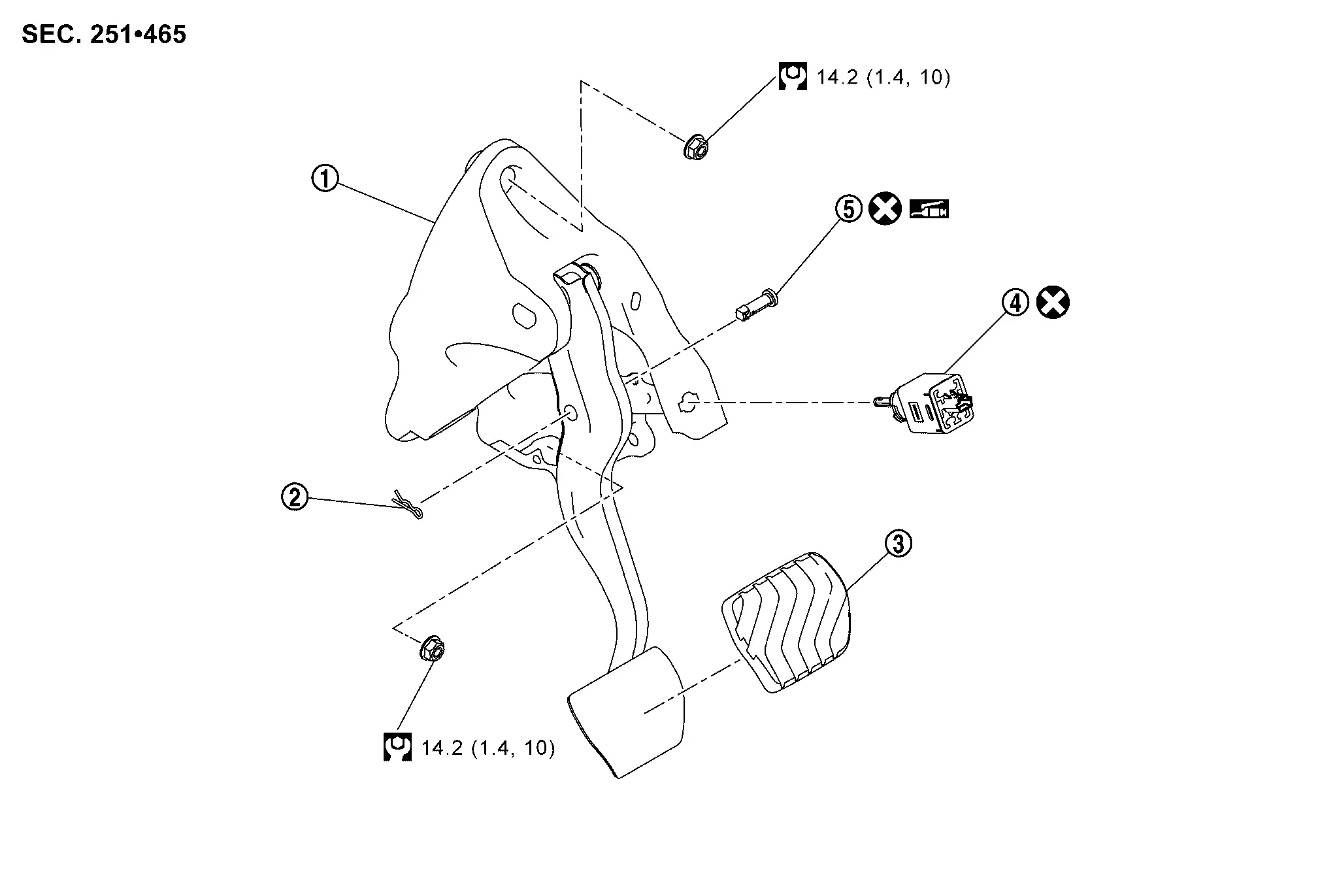
BRAKE PEDAL : Exploded View
 |
Brake pedal assembly |  |
Snap pin |  |
Brake pedal pad |
 |
Stop lamp switch |  |
Clevis pin | ||
 |
: N·m (kg-m, ft-lb) | ||||
 |
: Apply Nissan multi-purpose Special Grease No. 2. | ||||
 |
: Always replace after every disassembly. | ||||
BRAKE PEDAL : Removal & Installation
REMOVAL
Disconnect 12V battery negative terminal. Refer to Removal & Installation.
Remove instrument lower panel. Refer to Removal & Installation.
Remove instrument finisher B. Refer to Removal & Installation.
Remove screw  .
.
Remove mounting nuts , and then remove bracket .
Remove negative harness mounting bolt and screw  , and then remove bracket.
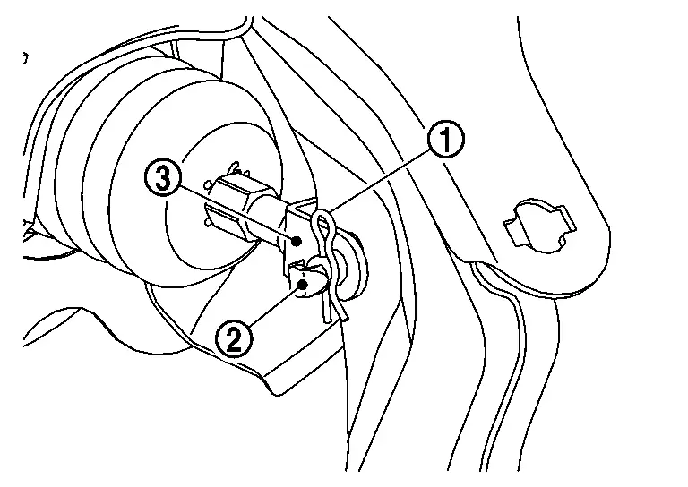
Disconnect the stop lamp switch harness connector.
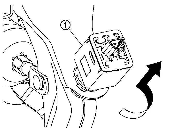
Remove stop lamp switch 90° rotate the stop lamp switch counterclockwise.
Disconnect the accelerator pedal harness connector.
Remove snap pin and clevis pin form the clevis .
Remove harness clip from brake pedal assembly.
Remove electrically-driven intelligent brake unit mounting nuts and brake pedal assembly mounting nuts and then remove brake pedal assembly from the Nissan Ariya vehicle.
CAUTION:
To prevent damage to the parts, never drop electrically-driven intelligent brake unit.
Remove accelerator pedal from brake pedal assembly. Refer to Removal & Installation.
Perform inspection after removal. Refer to Inspection and Adjustment.
INSTALLATION
Note the following, and install in the reverse order of removal.
-
Never reuse the clevis pin.
-
Apply the Nissan multi-purpose Special Grease No. 2 to the clevis pin and the mating faces. (Not necessary if grease has been already applied)
 NOTE:
NOTE:
The clevis pin may be inserted in either direction.
-
Never impact brake pedal such as drop and interference with tools and parts.
-
Replace brake pedal when impacting brake pedal.
-
Perform adjustment after installation. Refer to Inspection and Adjustment.
BRAKE PEDAL : Inspection and Adjustment
INSPECTION AFTER REMOVAL
Check the brake pedal assembly for bend, damage, and cracks on the welded parts. If any is found, replace brake pedal assembly.
ADJUSTMENT AFTER INSTALLATION
-
Adjust each item of brake pedal after installing the brake pedal assembly to the vehicle. Refer to Periodic Maintenance Operation .
-
Perform the release position learning of the accelerator pedal. Refer to Work Procedure.
-
Front Brake Piping Nissan Ariya SUV
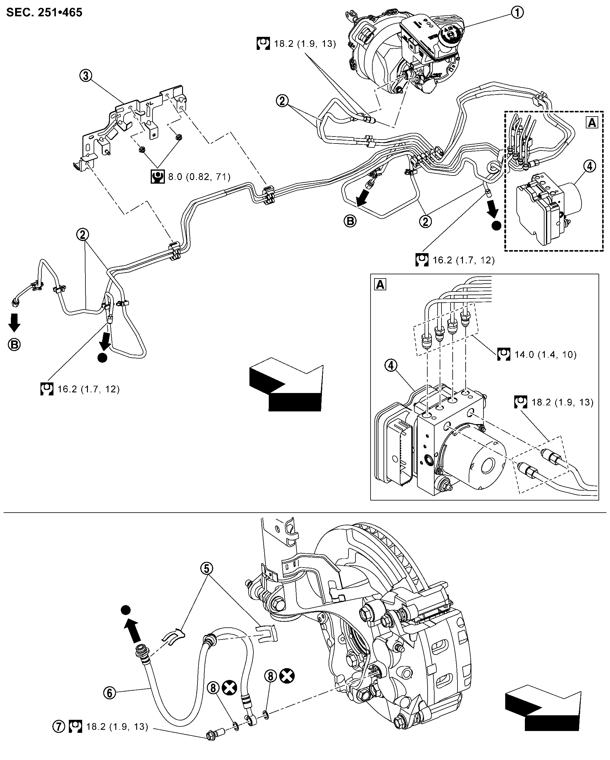
FRONT BRAKE PIPING : Exploded View
|
electrically-driven intelligent brake unit | |
Brake tube | |
Bracket |
|
ABS actuator and electric unit (control unit) | |
Lock plate |  |
Brake hose |
 |
Union bolt |  |
Copper washer | ||
|
To rear brake tube. Refer to Exploded View. | ||||
 |
: Nissan Ariya Vehicle front | ||||
|
: N·m (kg-m, ft-lb) | ||||
 |
: N·m (kg-m, in-lb) | ||||
|
: Always replace after every disassembly. | ||||
 |
: Indicates that the part is connected at points with same symbol in actual Nissan Ariya vehicle. | ||||
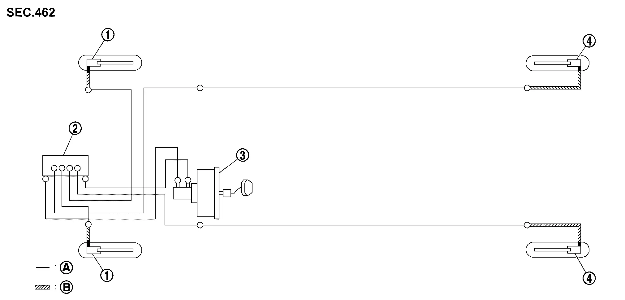
FRONT BRAKE PIPING : Hydraulic Layout
|
Front disc brake | |
ABS actuator and electric unit (control unit) | |
Electrically-driven intelligent brake unit |
|
Rear disc brake | ||||
|
Brake tube | |
Brake hose | ||
 |
: Flare nut | ||||
 |
: Union bolt | ||||
FRONT BRAKE PIPING : Removal & Installation
REMOVAL
CAUTION:
-
Never spill or splash brake fluid on painted surfaces. Brake fluid may seriously damage paint. Wipe it off immediately and wash with water if it gets on a painted surface. For brake component parts, never wash them with water.
-
Never depress the brake pedal while removing the brake hose or brake tube. If this is not complied with, brake fluid may splash.
Remove tires. Refer to Removal and Installation.
Drain brake fluid. Refer to Draining.
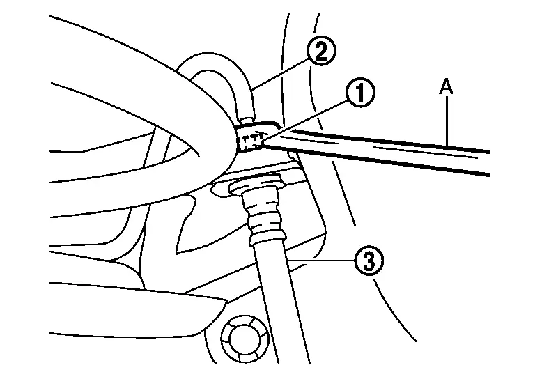
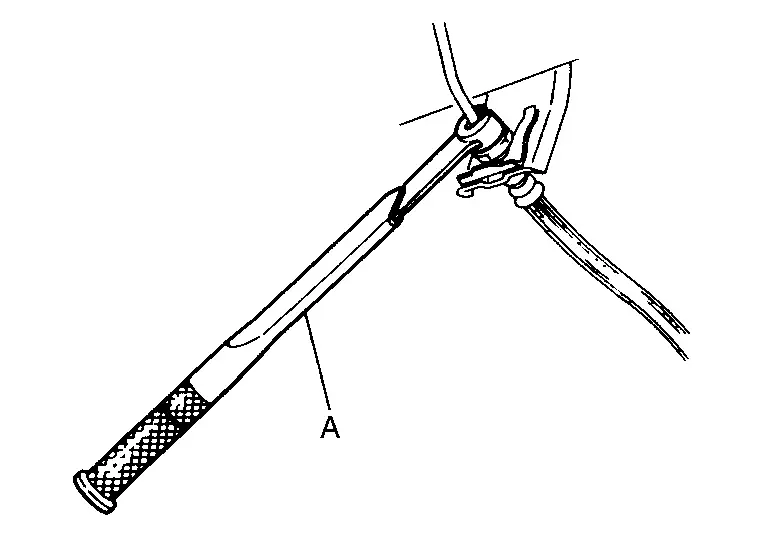
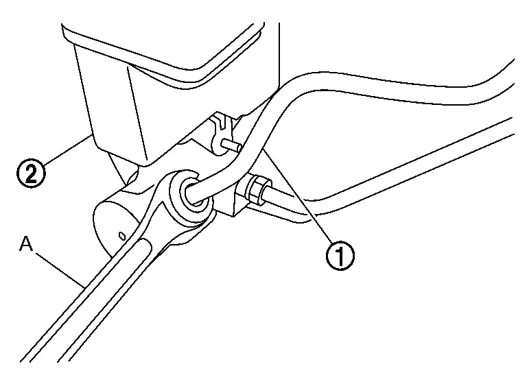
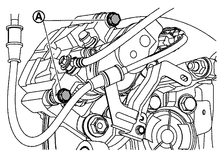
Loosen the flare nut with a flare nut wrench (A) and separate the brake tube from the brake hose .
CAUTION:
-
Never scratch the flare nut and the brake tube.
-
Never bend sharply, twist or strongly pull out the brake hoses and tubes.
-
Cover open end of brake tubes and hoses when disconnecting to prevent entrance of dirt.
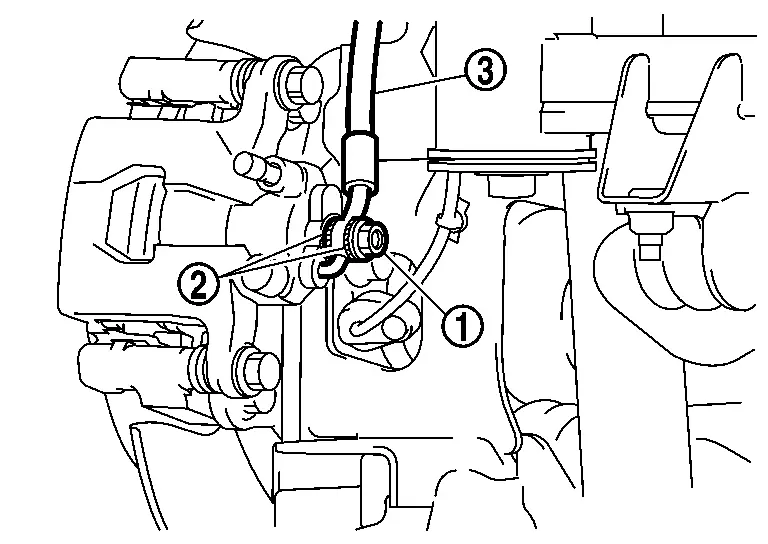
Remove the union bolt and copper washers , and remove the brake hose from the brake caliper assembly.
Remove the lock plate and remove the brake hose.
INSTALLATION
CAUTION:
-
Never spill or splash brake fluid on painted surfaces. Brake fluid may seriously damage paint. Wipe it off immediately and wash with water if it gets on a painted surface. For brake component parts, never wash them with water.
-
Never depress the brake pedal while removing the brake hose or brake tube. If this is not complied with, brake fluid may splash.
-
Never allow foreign matter (e.g. dust) and oils other than brake fluid to enter the reservoir tank.
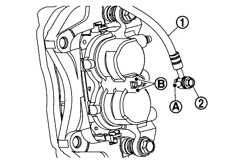
Assemble the union bolt and the copper washer to the brake hose .
CAUTION:
Never reuse the copper washer.
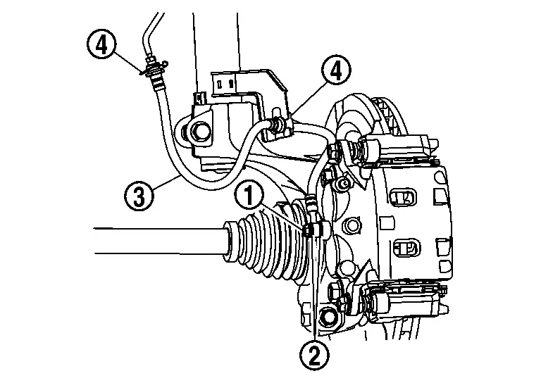
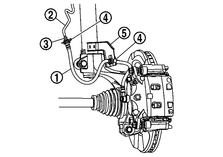
Align the brake hose pin with the brake caliper assembly projection , and tighten the union bolt to the specified torque.
Install the brake tube to the brake hose , temporarily tighten the flare nut by hand until it does not rotate further, and fix the brake hose to the bracket with the lock plate .
CAUTION:
Check that all brake hoses and brake tubes are not twisted and bent.
Tighten the flare nut to the specified torque with a flare nut torque wrench (A).
CAUTION:
Never scratch the flare nut and the brake tube.
Refill with new brake fluid and perform the air bleeding. Refer to Bleeding Brake System.
CAUTION:
Never reuse drained brake fluid.
Install tires. Refer to Removal and Installation.
Perform inspection after installation. Refer to Inspection.
FRONT BRAKE PIPING : Inspection
INSPECTION AFTER INSTALLATION
Check the brake hoses and tubes for the following: no scratches; no twist and deformation; no interference with other components when steering the steering wheel; no looseness at connections.
CAUTION:
Clearance with brake hose and each parts being secured more than 10 mm (0.39 in) in unladen condition*.
*: Fuel, engine coolant and lubricant are quantity to specified. Spare tire, jack, hand tools and mats are brought out of Nissan Ariya vehicle.
Depress the brake pedal with a force of 785 N (80 kg, 176 lb) and hold down the pedal for approximately 5 seconds with the engine running. Check for any fluid leakage.
CAUTION:
Retighten the applicable connection to the specified torque and repair any abnormal (damaged, worn or deformed) part if any brake fluid leakage is present.
Rear Brake Piping Nissan Ariya first Gen
REAR BRAKE PIPING : Exploded View
2WD MODELS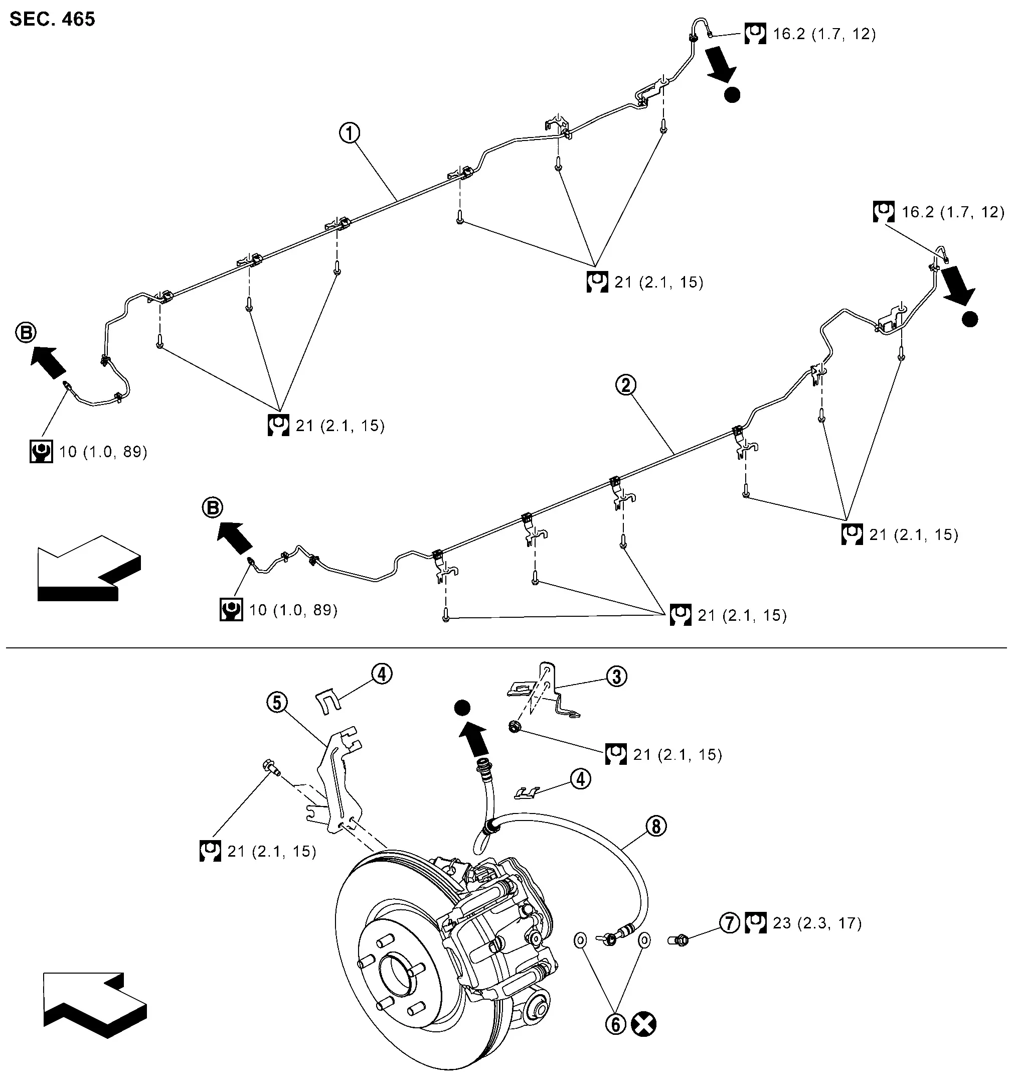
|
Brake tube RH | |
Brake tube LH | |
Bracket |
|
Lock plate | |
Bracket | |
Aluminum washer |
|
Union bolt | |
Brake hose | ||
|
To front brake tube. Refer to Exploded View. | ||||
|
: Nissan Ariya Vehicle front | ||||
|
: N·m (kg-m, ft-lb) | ||||
|
: N·m (kg-m, in-lb) | ||||
|
: Always replace after every disassembly. | ||||
|
: Indicates that the part is connected at points with same symbol in actual Nissan Ariya vehicle. | ||||
4WD MODELS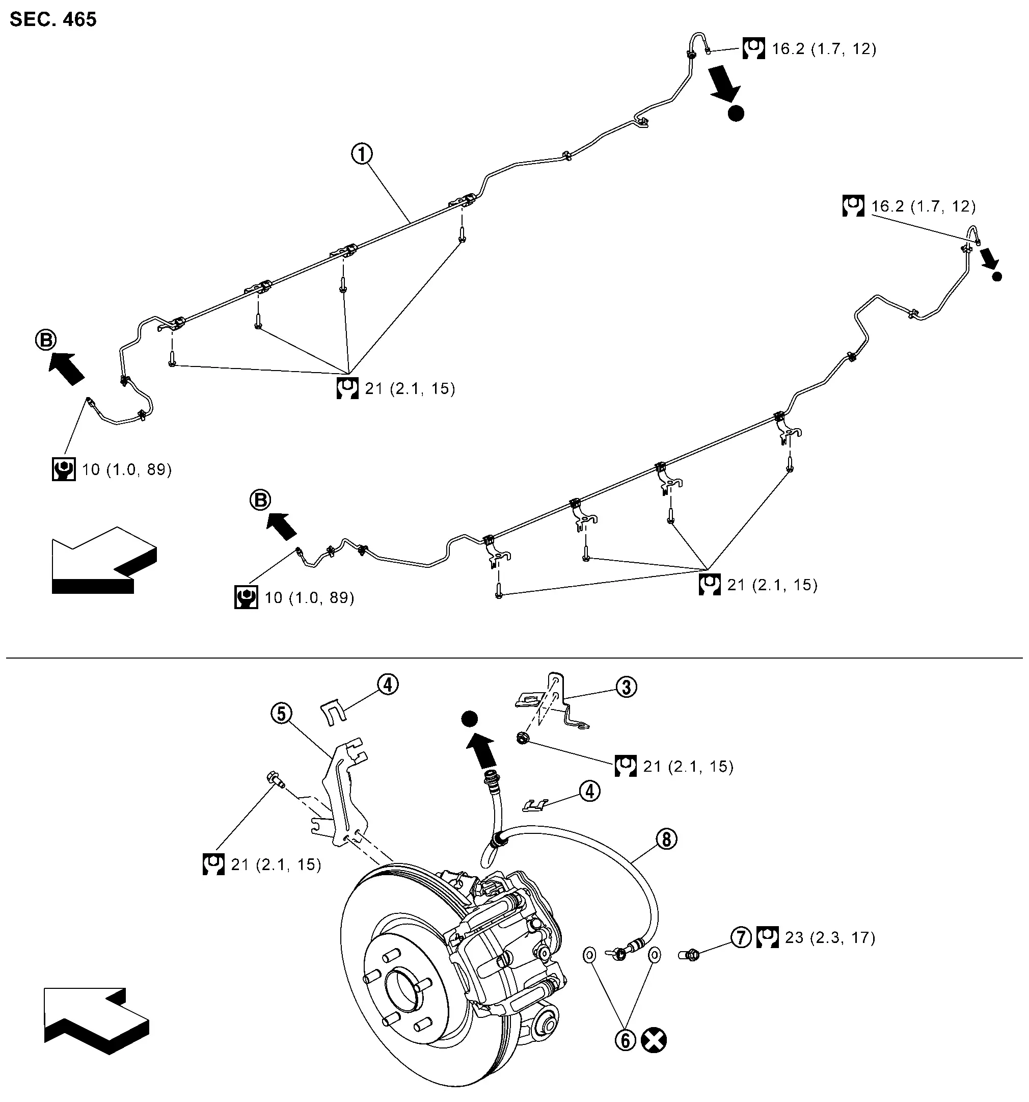
|
Brake tube RH | |
Brake tube LH | |
Bracket |
|
Lock plate | |
Bracket | |
Aluminum washer |
|
Union bolt | |
Brake hose | ||
|
To front brake tube. Refer to Exploded View. | ||||
|
: Nissan Ariya Vehicle front | ||||
|
: N·m (kg-m, ft-lb) | ||||
|
: N·m (kg-m, in-lb) | ||||
|
: Always replace after every disassembly. | ||||
|
: Indicates that the part is connected at points with same symbol in actual Nissan Ariya vehicle. | ||||
REAR BRAKE PIPING : Hydraulic Layout
|
Front disc brake | |
ABS actuator and electric unit (control unit) | |
Electrically-driven intelligent brake unit |
|
Rear disc brake | ||||
|
Brake tube | |
Brake hose | ||
|
: Flare nut | ||||
|
: Union bolt | ||||
REAR BRAKE PIPING : Removal & Installation
REMOVAL
CAUTION:
-
Never spill or splash brake fluid on painted surfaces. Brake fluid may seriously damage paint. Wipe it off immediately and wash with water if it gets on a painted surface. For brake component parts, never wash them with water.
-
Never depress the brake pedal while removing the brake hose or brake tube. If this is not complied with, brake fluid may splash.
-
Wipe off immediately when attaching brake fluid with disc rotor and caliper assembly.
Remove tires. Refer to Removal and Installation.
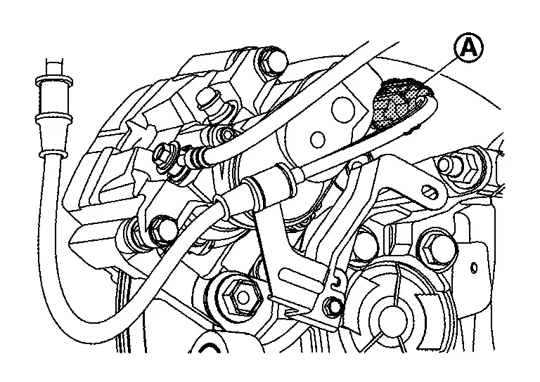
Remove the lock plate , then remove the brake hose from the brake tube bracket.
Loosen the flare nut with a flare nut wrench (A) and separate the brake tube from the brake hose .
CAUTION:
-
Never scratch the flare nut and the brake tube.
-
Never bend sharply, twist or strongly pull out the brake hoses and tubes.
-
Cover open end of brake tubes and brake hoses when disconnecting to prevent entrance of dirt.
Remove the lock plate , then remove the brake tube B from the brake tube bracket.
Remove the union bolt and aluminum washers , and remove the brake hose from the brake caliper assembly.
INSTALLATION
CAUTION:
-
Never spill or splash brake fluid on painted surfaces. Brake fluid may seriously damage paint. Wipe it off immediately and wash with water if it gets on a painted surface. For brake component parts, never wash them with water.
-
Never depress the brake pedal while removing the brake hose or brake tube. If this is not complied with, brake fluid may splash.
-
Never allow foreign matter (e.g. dust) and oils other than brake fluid to enter the reservoir tank.
-
Wipe off immediately when attaching brake fluid with disc rotor and caliper assembly.
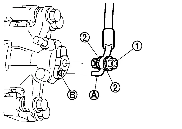
Assemble the union bolt and the aluminum washers to the brake hose.
CAUTION:
Never reuse the aluminum washer.
Align the brake hose L-pin with the brake caliper assembly hole , and tighten the union bolt to the specified torque.
Install the brake hose to the brake tube, temporarily tighten the flare nut by hand until it does not rotate further, and fix the brake hose to the brake hose bracket with the lock plate.
CAUTION:
Check that all brake hoses and brake tubes are not twisted and bent.
Tighten the flare nut to the specified torque with a flare nut torque wrench (A).
CAUTION:
Never scratch the flare nut and the brake tube.
Refill with new brake fluid and perform the air bleeding. Refer to Bleeding Brake System.
CAUTION:
Never reuse drained brake fluid.
Install tires. Refer to Removal and Installation.
Perform inspection after installation. Refer to Inspection.
REAR BRAKE PIPING : Inspection
INSPECTION AFTER INSTALLATION
Check the brake hoses and tubes for the following: no scratches; no twist and deformation; no looseness at connections.
CAUTION:
Clearance with brake hose and each parts being secured more than 10 mm (0.39 in) in unladen condition*.
*: Fuel, engine coolant and lubricant are quantity to specified. Spare tire, jack, hand tools and mats are brought out of Nissan Ariya vehicle.
Depress the brake pedal with a force of 785 N (80 kg, 176 lb) and hold down the pedal for approximately 5 seconds with the engine running. Check for any fluid leakage.
CAUTION:
Retighten the applicable connection to the specified torque and repair any abnormal (damaged, worn or deformed) part if any brake fluid leakage is present.
Brake Power Supply Backup Unit Nissan Ariya SUV
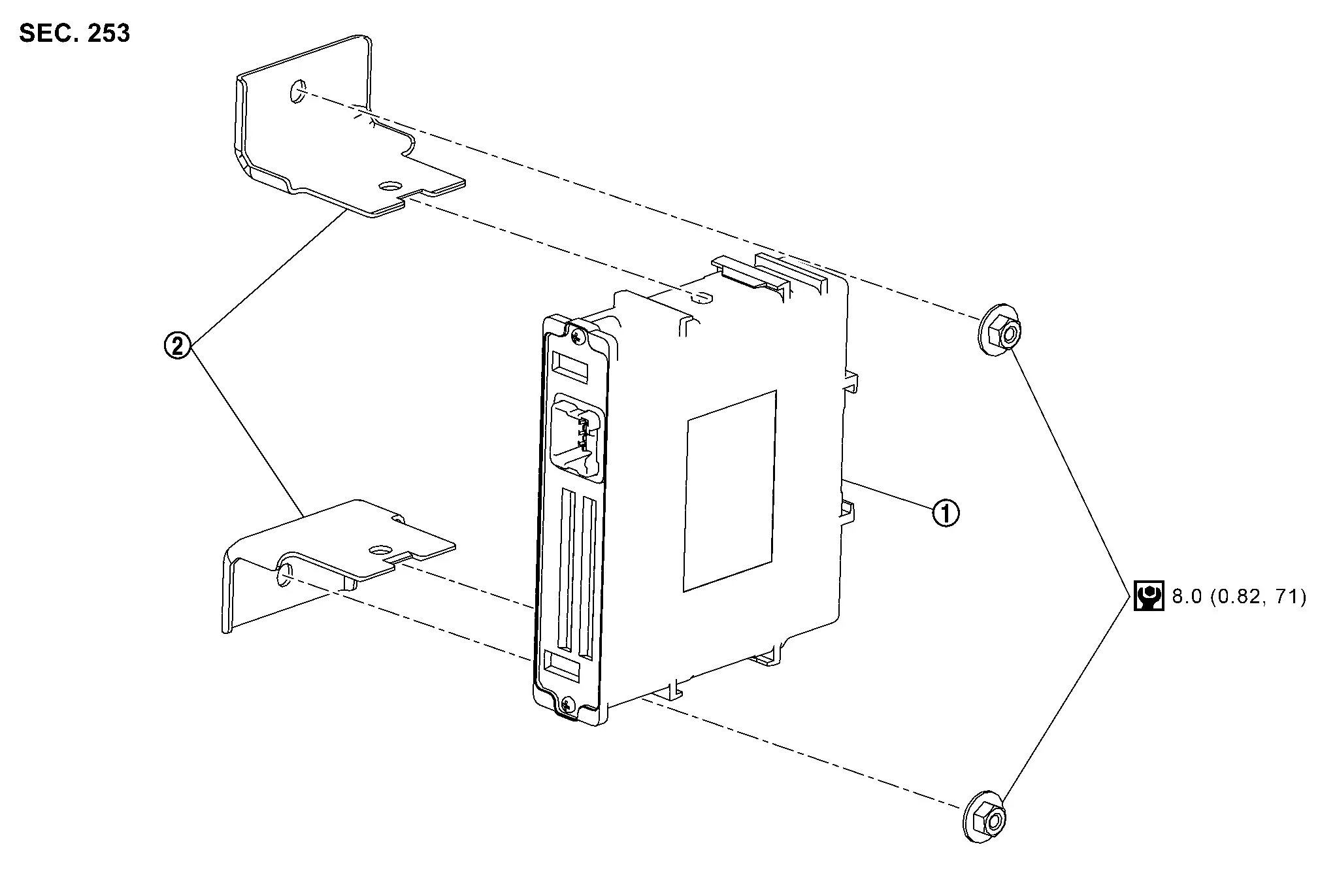
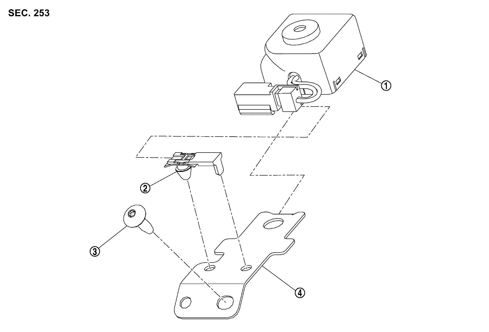
BRAKE POWER SUPPLY BACKUP UNIT : Exploded View
|
Brake power supply backup unit | |
Bracket | ||
|
: N·m (kg-m, in-lb) | ||||
BRAKE POWER SUPPLY BACKUP UNIT : Removal & Installation
REMOVAL
Power switch OFF and disconnect CONSULT from DDL2 diagnosis connector.
Check that room lamps are turned OFF after closing all doors including back door, and then wait for 3 minutes or more at out side of Nissan Ariya vehicle.
CAUTION:
Never touch the vehicle during waiting.
Remove luggage side lower finisher (right).Refer to Removal & Installation.
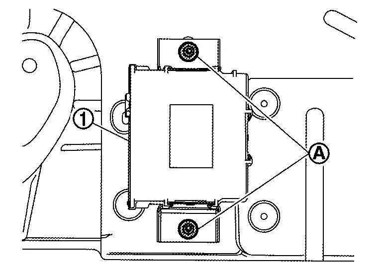
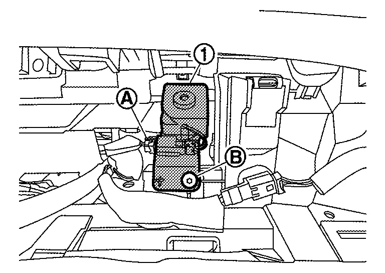
Disconnect brake power supply backup unit harness connector.
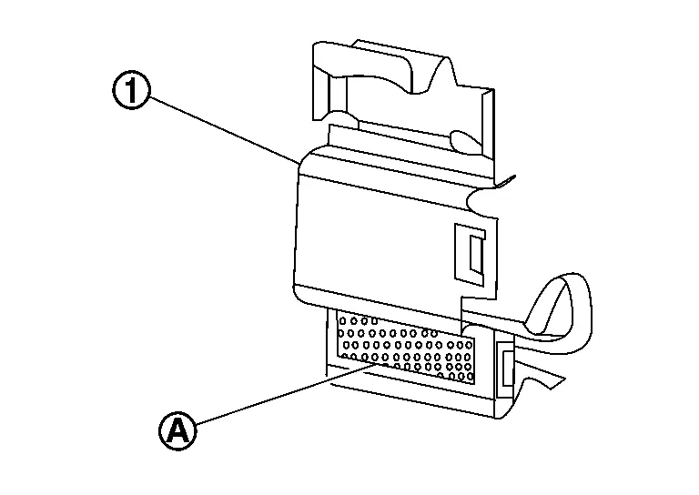
Remove nut and then remove brake power supply backup unit assembly .
CAUTION:
Never drop parts after removal.
Remove bracket from brake power supply backup unit.
INSTALLATION
Note the following, and install in the reverse order of removal.
-
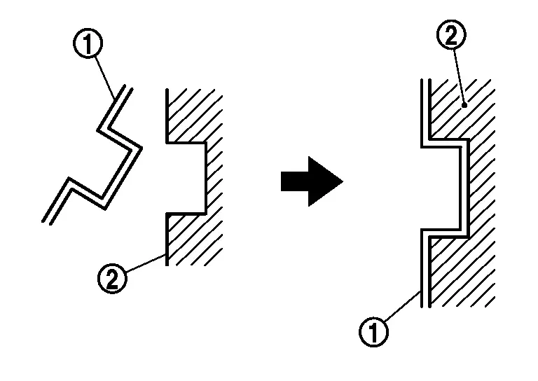
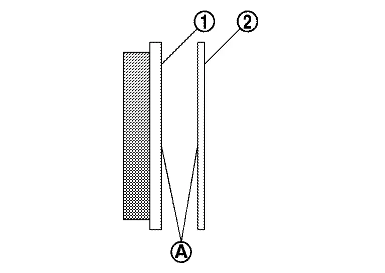
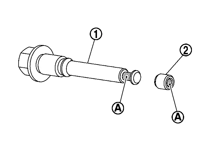
Align the direction of alphabet letters on the brake power supply backup unit
with the direction of the same alphabet letters on the bracket .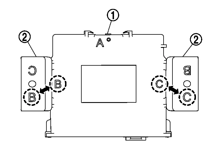
-
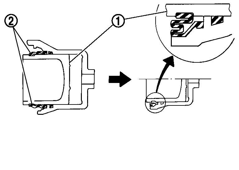
When installing bracket
to brake power supply backup unit , make sure to insert protrusion of brake power supply backup to lock hole of bracket unit protrudes from the opposite side of the lock hole.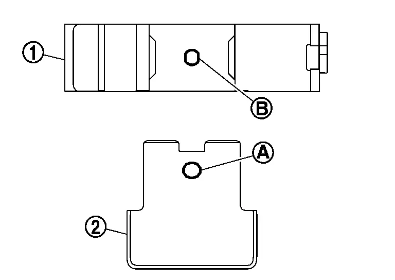
Electrically-Driven Intelligent Brake Unit Nissan Ariya 2023
ELECTRICALLY-DRIVEN INTELLIGENT BRAKE UNIT : Exploded View
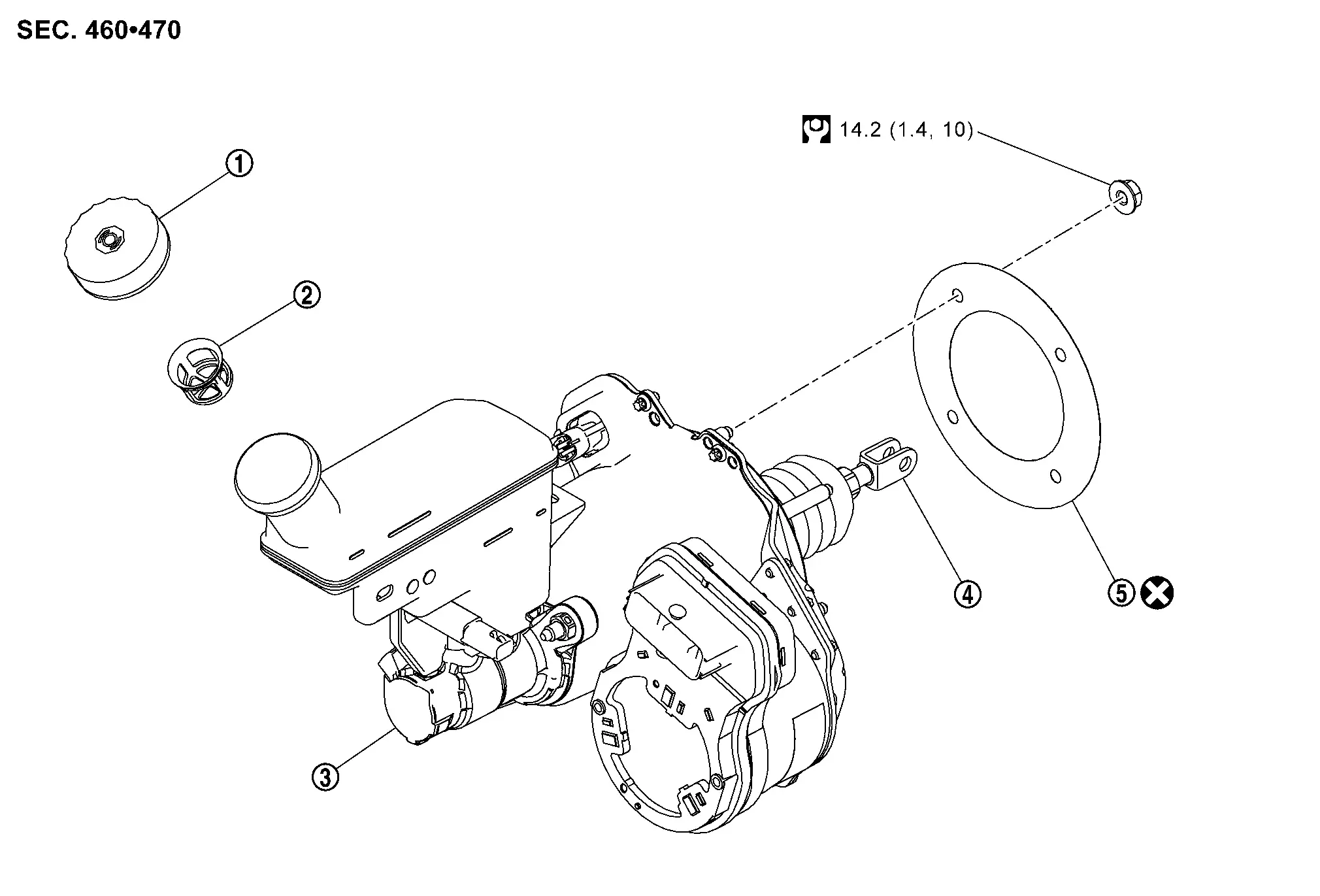
|
Reservoir cap | |
Oil strainer | |
Electrically-driven intelligent brake unit |
|
Clevis | |
Gasket | ||
|
: N·m (kg-m, ft-lb) | ||||
|
: Always replace after every disassembly. | ||||
ELECTRICALLY-DRIVEN INTELLIGENT BRAKE UNIT : Removal & Installation
REMOVAL
CAUTION:
-
While electrically-driven intelligent brake unit
is removed, hold part with hand.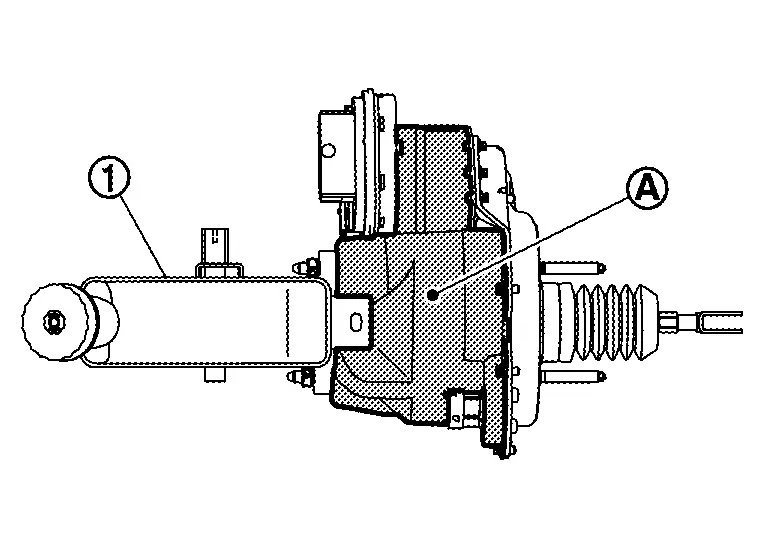
-
Never disassemble electrically-driven intelligent brake unit.
-
Never spill or splash brake fluid on painted surfaces. Brake fluid may seriously damage paint. Wipe it off immediately and wash with water if it gets on a painted surface. For brake component parts, never wash them with water.
-
Never depress brake pedal during removal and installation of brake hose because brake fluid may scatter.
Perform inspection before removal. Refer to Inspection and Adjustment.
Power switch OFF and disconnect CONSULT from DDL2 diagnosis connector.
Check that room lamps are turned OFF after closing all doors including back door, and then wait for 3 minutes or more at out side of Nissan Ariya vehicle.
Disconnect negative terminal of 12 V battery. Refer to Removal and Installation.
Drain brake fluid. Refer to Draining.
Remove cowl top member. Refer to Removal & Installation.
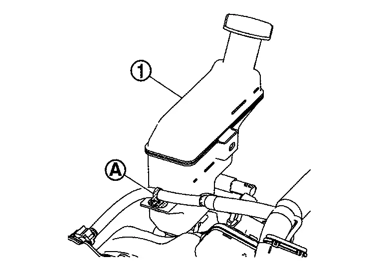
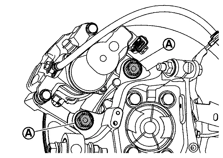
Separate the brake tube from electrically-driven intelligent brake unit with a flare nut wrench (A).
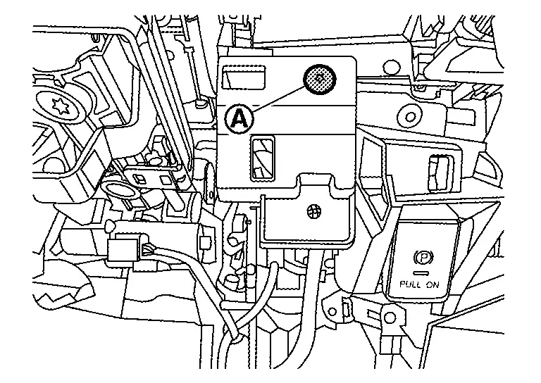
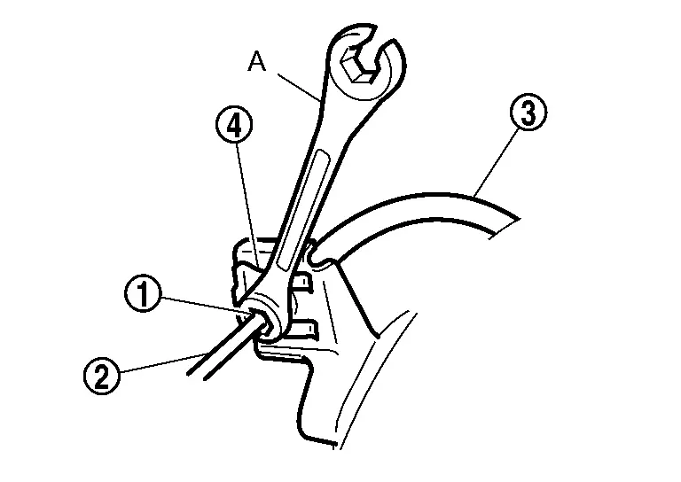
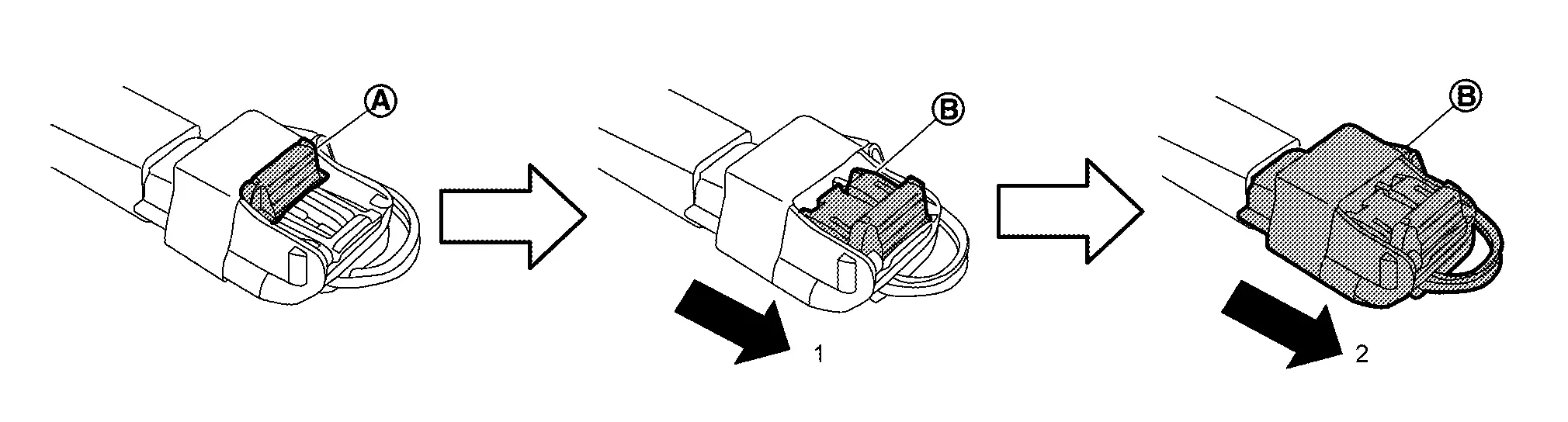
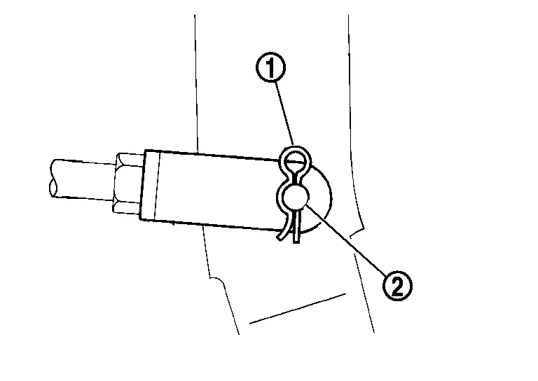
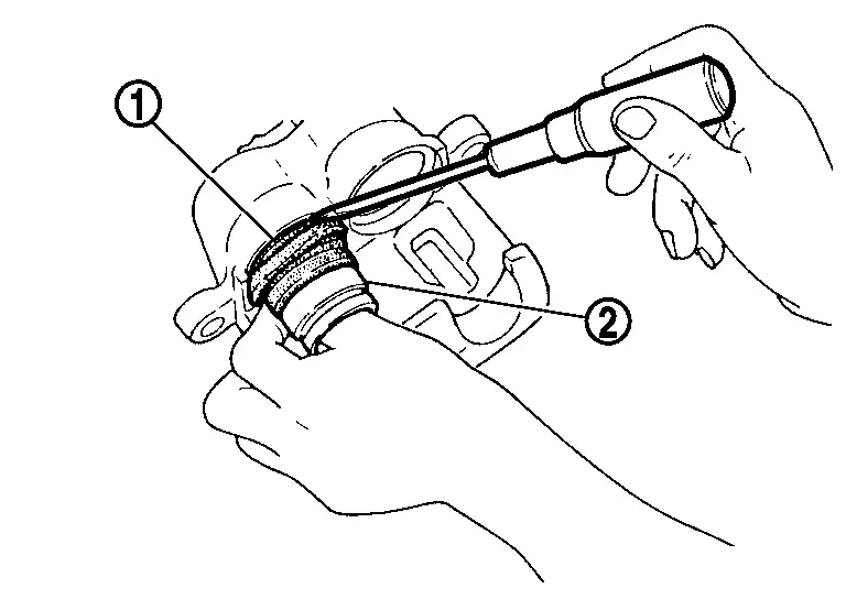
Remove brake fluid level switch as follows;Slide connector lock to right (1) of Nissan Ariya vehicle. While connector lock is pushed in , disconnect brake fluid level switch harness connector in lateral direction (2) of Nissan Ariya vehicle.
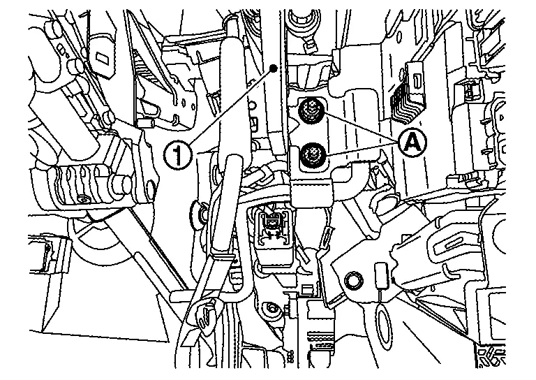
Disconnect electrically-driven intelligent brake unit harness connector as follows;
 direction. Disconnect electrically-driven intelligent brake unit harness connector.
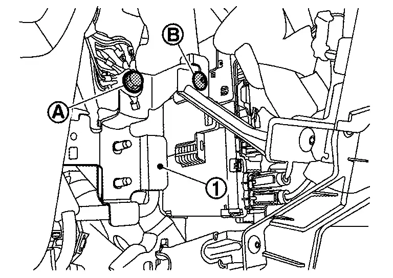
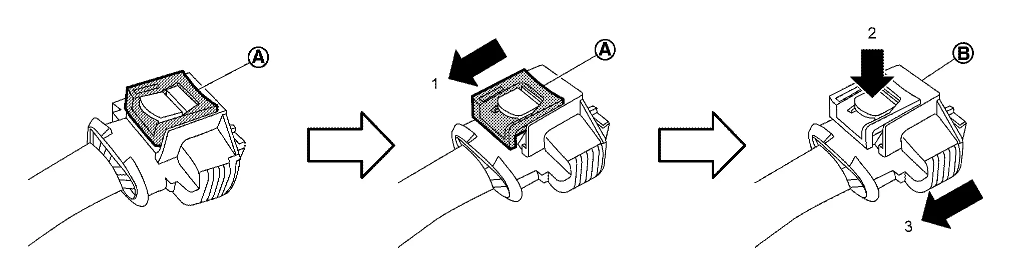
Disconnect stroke sensor harness connector as follows;Slide connector lock to right (1) of Nissan Ariya vehicle. While connector lock (2) is pushed in , disconnect stroke sensor harness connector in the front direction (3) of Nissan Ariya vehicle.
Remove stroke sensor harness clip behind brake master cylinder .
Remove snap pin and clevis pin from clevis.
Remove brake pedal bracket assembly. Refer to. Removal & Installation.
CAUTION:
Hold electrically-driven intelligent brake unit to prevent it from dropping.
Remove electrically-driven intelligent brake unit mounting nut.
Remove electrically-driven intelligent brake unit.
CAUTION:
Never deform the brake tube when removing electrically-driven intelligent brake unit.
Remove gasket from electrically-driven intelligent brake unit.
INSTALLATION
CAUTION:
When installing electrically-driven intelligent brake unit, never deform brake tube.
-
If electrically-driven intelligent brake unit is dropped or impacted, replace electrically-driven intelligent brake unit assembly.
-
When installing, hold part
of electrically-driven intelligent brake unit. -
Never apply grease or lubricant to the parts that contact with brake fluid and rubber parts.
-
Never spill or splash brake fluid on painted surfaces. Brake fluid may seriously damage paint. Wipe it off immediately and wash with water if it gets on a painted surface. For brake component parts, never wash them with water.
-
Never depress brake pedal during removal and installation of brake hose because brake fluid may scatter.
Note the following, and install in the reverse order of removal.
-
Never crush threads of stud bolts of the electrically-driven intelligent brake unit. When installing diagonally, the dash panel may damage the threads.
-
Never deform brake tube when installing electrically-driven intelligent brake unit.
-
Never reuse clevis pin.
-
Temporarily tighten flare nut of brake tube
by hand, and then install it to the electrically-driven intelligent brake unit to the specified tightening torque using flare nut torque wrench (commercial tool) (A). Refer to Exploded View. -
After installing electrically-driven intelligent brake unit harness connector
, move lever part in the  direction until it locks, and push in lock part
  to lock it securely.
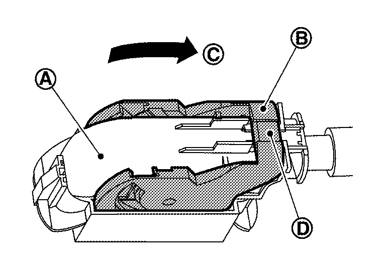
-
Install stroke sensor harness connector as follows;
-
Insert connector lock
into electrically-driven intelligent brake unit (1). -
Push in the connector lock
in the (2) direction and securely lock.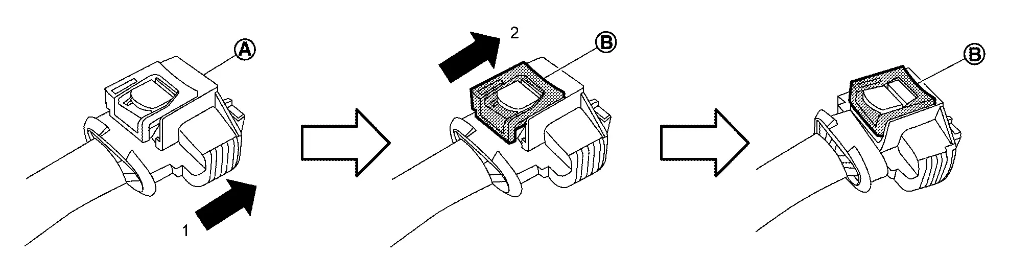
-
-
Install brake fluid level switch harness connector as follows;
-
Insert connector
to brake fluid level switch. -
Push in connector lock
in the (2) direction and securely lock.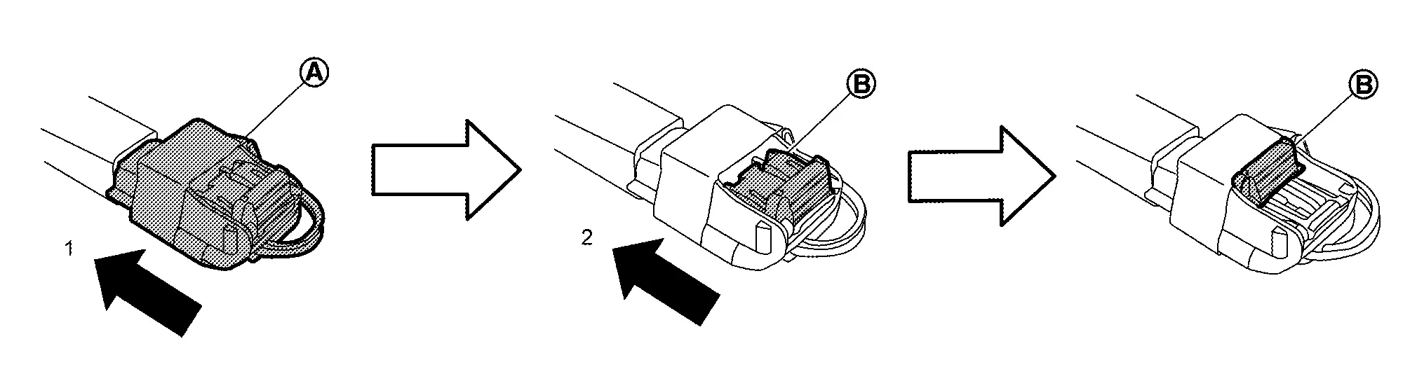
-
-
Perform air bleeding. Refer to Air Bleeding.
-
Check brake pedal for each item, adjust when there is deviation from the specified value. Refer to Periodic Maintenance Operation.
ELECTRICALLY-DRIVEN INTELLIGENT BRAKE UNIT : Inspection
INSPECTION BEFORE REMOVAL
Check brake fluid level switch. Refer to DTC Diagnosis Procedure.
INSPECTION AFTER REMOVAL
Check the following items, and replace the part if necessary.
-
Check for damage, deformation, interference with the other parts, and looseness of connection.
-
Check for fluid leakage from connection. Refer to Inspection
CAUTION:
When fluid leakage is occurred, tighten each bolt to the specified torque. Replace parts if there is still leakage.
INSPECTION AFTER INSTALLATION
Must be performed additional service when replacing electrically-driven intelligent brake unit. Refer to Description.
Warning Buzzer Nissan Ariya: FE0
WARNING BUZZER : Exploded View
|
Warning buzzer | |
Clip | |
Screw |
|
Bracket |
WARNING BUZZER : Removal & Installation
REMOVAL
Remove integrated interface display. Refer. Removal & Installation.
Disconnect warning buzzer harness connector .
Remove mounting screw and the remove warning buzzer .
INSTALLATION
Note the following, and install in the reverse order of removal.
Front Brake Pad Nissan Ariya 2023
FRONT BRAKE PAD : Exploded View
FOR 31 SIZE NAO MODELS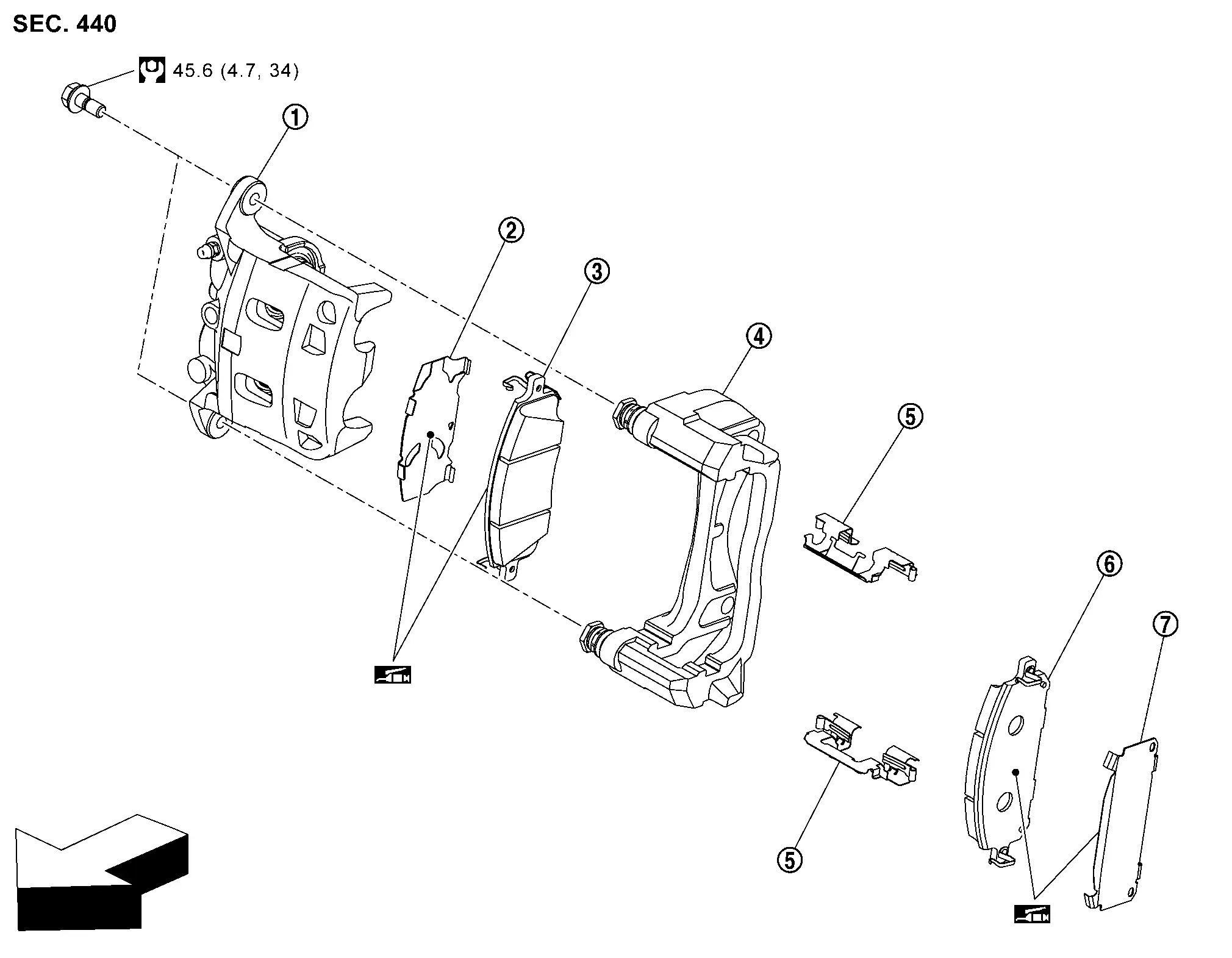
|
Cylinder body | |
Inner shim | |
Inner pad (with pad wear sensor) |
|
Torque member | |
Pad retainer | |
Outer pad (with pad wear sensor) |
|
Outer shim | ||||
|
: Nissan Ariya Vehicle front | ||||
|
: N·m (kg-m, ft-lb) | ||||
|
: Nissan disc brake shim grease | ||||
FOR 36 SIZE NAO MODELS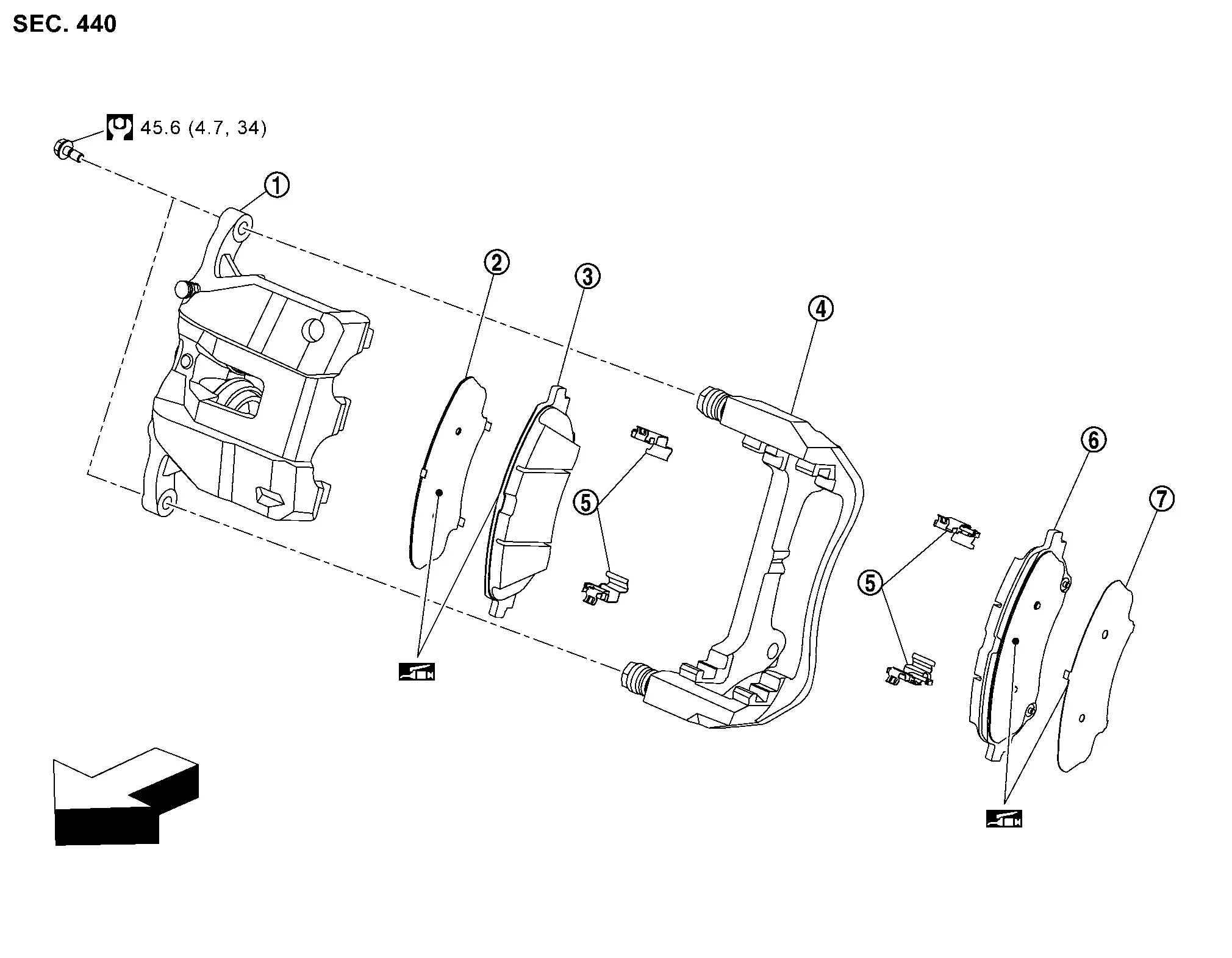
|
Cylinder body | |
Inner shim | |
Inner pad (with pad wear sensor) |
|
Torque member | |
Pad retainer (VHB foil) | |
Outer pad |
|
Outer shim | ||||
|
: Nissan Ariya Vehicle front | ||||
|
: N·m (kg-m, ft-lb) | ||||
|
: Nissan disc brake shim grease | ||||
FRONT BRAKE PAD : Removal & Installation
FOR NAO 31 SIZE MODELS
REMOVAL
WARNING:
Remove dust covering brake caliper assembly and brake pad with a dust collector. Never splatter the dust with an air blow gun.
CAUTION:
-
Never depress the brake pedal while removing the brake pads because the piston may pop out.
-
If the brake fluid or grease adheres to the brake caliper assembly and disc rotor, quickly wipe it off.
Remove tires. Refer to Removal and Installation.
Remove sliding pin bolt (lower side).
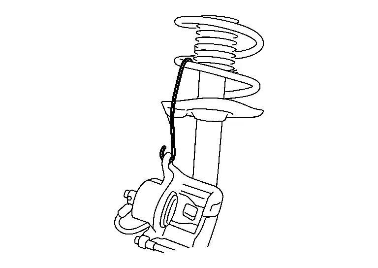
Hang cylinder body with suitable wire not to stretch brake hose.
Remove brake pads, shims, and pad retainer from torque member.
CAUTION:
-
When removing pad retainer
from torque member , never deform pad retainer.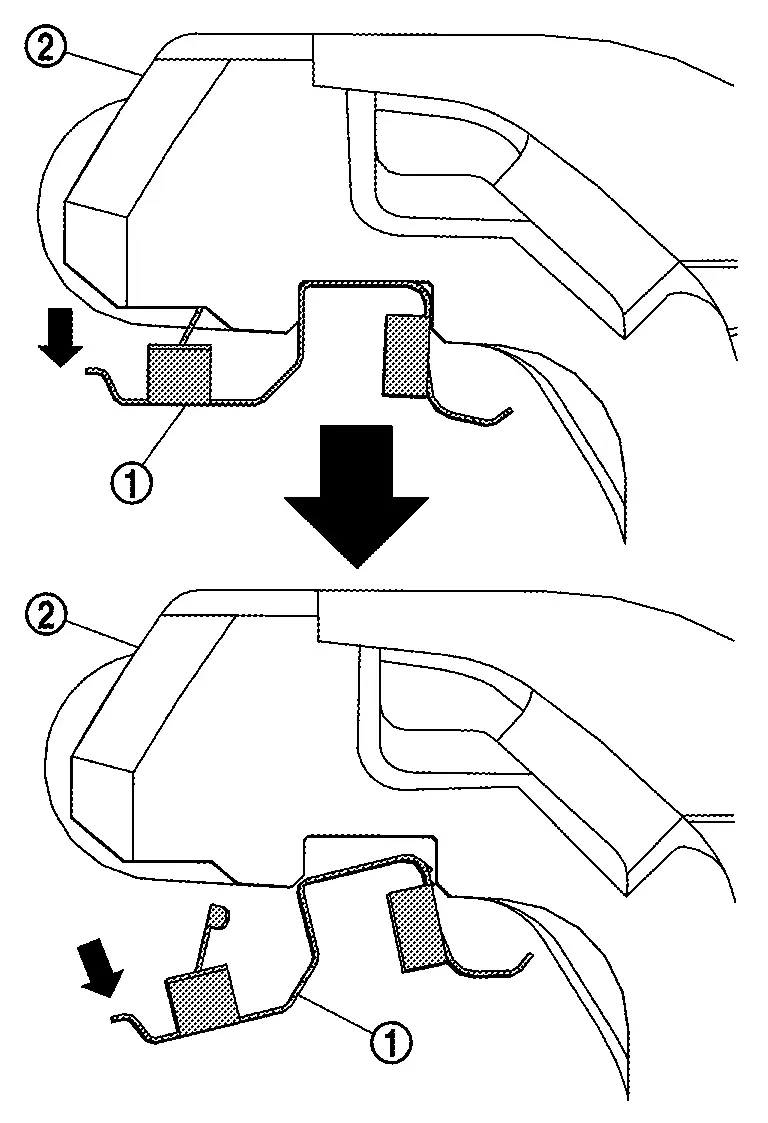
-
Never damage piston boots.
-
Never drop brake pads, and shims.
-
Distinguish each position of removed brake pads.
Perform inspection after removal. Refer to Inspection and Adjustment.
INSTALLATION
WARNING:
Remove dust covering brake caliper assembly and brake pad with a dust collector. Never splatter the dust with an air blow gun.
CAUTION:
-
Never depress brake pedal while removing brake pads because the piston may pop out.
-
If the brake fluid or grease adheres to disc rotor and cylinder body, quickly wipe it off.
Install pad retainers to torque members if pad retainers are removed before.
CAUTION:
-
Securely assemble pad retainers not to be lifted up from torque member.
-
Never deform pad retainers.
Apply Nissan disc brake shim grease to the matching surfaces between brake pad and shim cover , and install shim covers to brake pad.
CAUTION:
When replacing the brake pad always replace the shims and shim covers as a set.
Install brake pads to torque member.
CAUTION:
Never damage pad retainer.
Install cylinder body to torque member.
CAUTION:
-
Never damage piston boot.
-
When installing cylinder body, check brake fluid level in reservoir tank because brake fluid returns to reservoir tank of brake master cylinder assembly by pressing piston in.
NOTE:
Use disc brake piston tool (commercial tool) to press piston easily.
Install slide pin bolt (lower side) and tighten to the specified torque.
Check front disc brake for dragging, while depressing brake pedal several times. Refer to Inspection and Adjustment.
Install tires. Refer to Removal and Installation.
FOR NAO 36 SIZE MODELS
REMOVAL
WARNING:
Remove dust covering brake caliper assembly and brake pad with a dust collector. Never splatter the dust with an air blow gun.
CAUTION:
-
Never depress the brake pedal while removing the brake pads because the piston may pop out.
-
If the brake fluid or grease adheres to the brake caliper assembly and disc rotor, quickly wipe it off.
Remove tires. Refer to Removal and Installation.
Remove sliding pin bolt (lower side).
Hang cylinder body with suitable wire not to stretch brake hose.
Remove brake pads, shims, and pad retainer from torque member.
CAUTION:
-
When removing pad retainer
from torque member , never deform pad retainer. -
Never damage piston boots.
-
Never drop brake pads, and shims.
-
Distinguish each position of removed brake pads.
Perform inspection after removal. Refer to Inspection and Adjustment.
INSTALLATION
WARNING:
Remove dust covering brake caliper assembly and brake pad with a dust collector. Never splatter the dust with an air blow gun.
CAUTION:
-
Never depress brake pedal while removing brake pads because the piston may pop out.
-
If the brake fluid or grease adheres to disc rotor and cylinder body, quickly wipe it off.
Install pad retainers to torque members if pad retainers are removed before.
CAUTION:
-
Securely assemble pad retainers not to be lifted up from torque member.
-
Never deform pad retainers.
Install pad retainer with new VHB foil on pad retainer.
Apply Nissan disc brake shim grease to the matching surfaces between brake pad and shim cover , and install shim covers to brake pad.
CAUTION:
When replacing the brake pad always replace the shims and shim covers as a set.
Install brake pads to torque member.
CAUTION:
Never damage pad retainer.
Install cylinder body to torque member.
CAUTION:
-
Never damage piston boot.
-
When installing cylinder body, check brake fluid level in reservoir tank because brake fluid returns to reservoir tank of brake master cylinder assembly by pressing piston in.
NOTE:
Use disc brake piston tool (commercial tool) to press piston easily.
Install slide pin bolt (lower side) and tighten to the specified torque.
Check front disc brake for dragging, while depressing brake pedal several times. Refer to Inspection and Adjustment.
Install tires. Refer to Removal and Installation.
FRONT BRAKE PAD : Inspection
INSPECTION AFTER REMOVAL
-
Replace the shims and shim covers if rust is excessively occurred.
-
Eliminate rust on pad retainers and the torque member. Replace them if rust is excessively occurred.
INSPECTION AFTER INSTALLATION
Check front disc brake for a dragging. If any drag is felt, follow the procedure described below.
Remove brake pads. Refer to Removal and Installation.
Return pistons of caliper. Refer to Removal and Installation.
Install brake pads. Refer to Removal and Installation.
Depress brake pedal several times.
Check front disc brake for a dragging again. If any drag is felt, disassemble cylinder body. Replace if necessary. Refer to Disassembly and Assembly.
If brake pads are replaced or ground, or if braking force is felt strange, perform break-in work. Refer to Periodic Maintenance Operation.
Front Brake Caliper Assembly Nissan Ariya: FE0
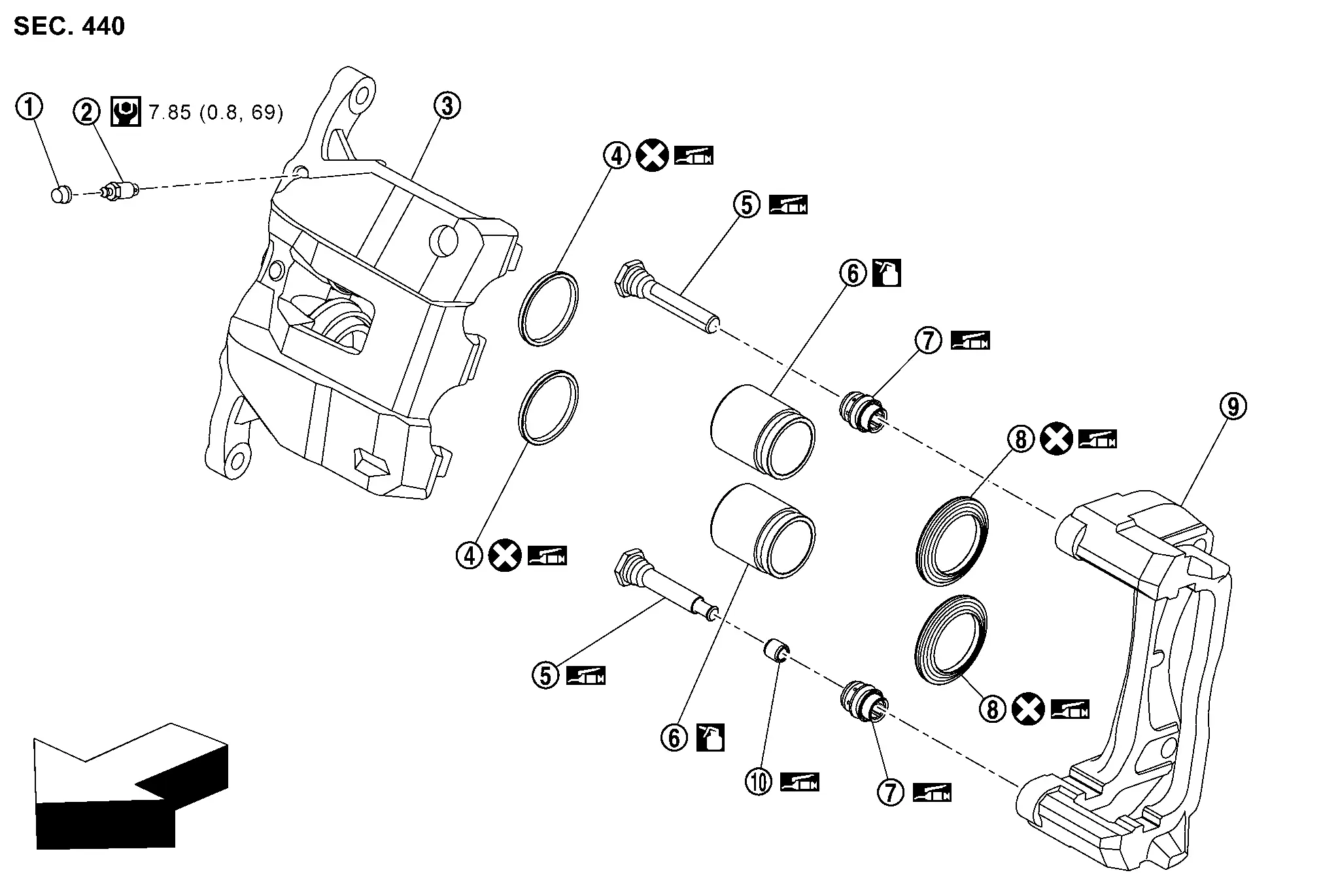
FRONT BRAKE CALIPER ASSEMBLY : Exploded View
FOR NAO 31 SIZE MODELS
REMOVAL
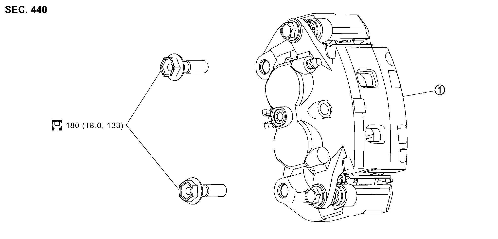
|
Brake caliper assembly | ||||
|
: N·m (kg-m, ft-lb) | ||||
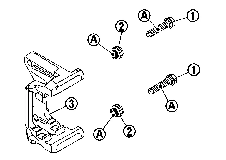
DISASSEMBLY
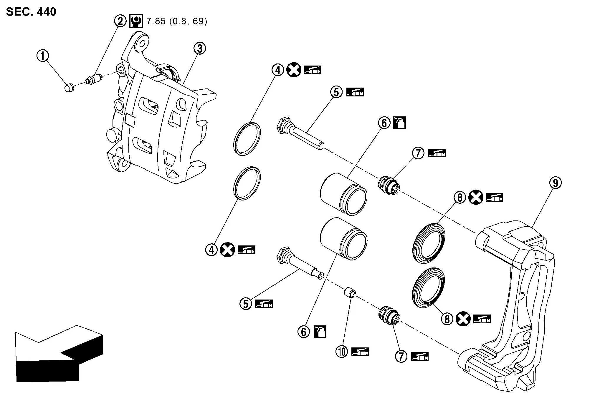
|
Cap | |
Bleeder valve | |
Cylinder body |
|
Piston seal | |
Sliding pin | |
Piston |
|
Sliding pin boot | |
Piston boot |  |
Torque member |
 |
Bushing | ||||
|
: Nissan Ariya Vehicle front | ||||
|
: N·m (kg-m, in-lb) | ||||
|
: NISSAN rubber grease. | ||||
 |
: NISSAN brake fluid No.2500 | ||||
|
: Always replace after every disassembly. | ||||
FOR NAO 36 SIZE MODELS
REMOVAL
|
Brake caliper assembly | ||||
|
: N·m (kg-m, ft-lb) | ||||
DISASSEMBLY
|
Cap | |
Bleeder valve | |
Cylinder body |
|
Piston seal | |
Sliding pin | |
Piston |
|
Sliding pin boot | |
Piston boot | |
Torque member |
|
Bushing | ||||
|
: Nissan Ariya Vehicle front | ||||
|
: N·m (kg-m, in-lb) | ||||
|
: NISSAN rubber grease. | ||||
|
: NISSAN brake fluid No.2500 | ||||
|
: Always replace after every disassembly. | ||||
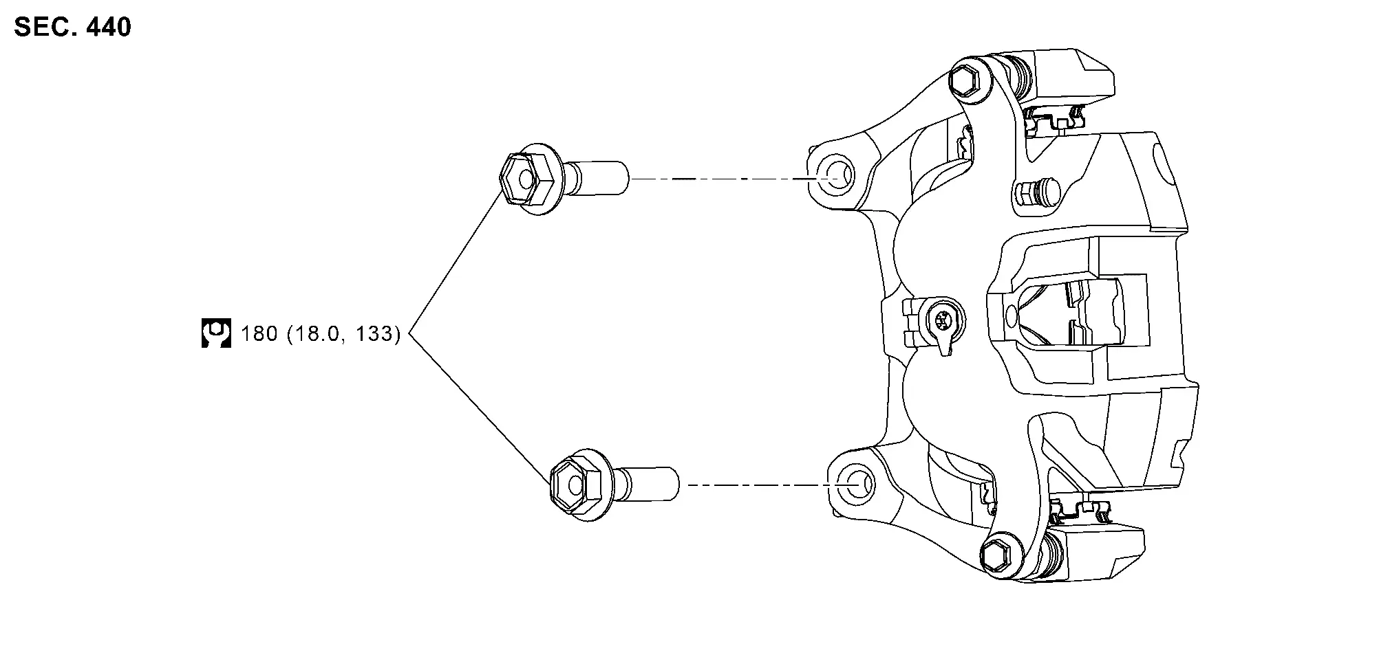
FRONT BRAKE CALIPER ASSEMBLY : Removal & Installation
REMOVAL
WARNING:
Remove dust covering brake caliper assembly and brake pad with a dust collector. Never splatter the dust with an air blow gun.
CAUTION:
-
Never spill or splash brake fluid on painted surfaces. Brake fluid may seriously damage paint. Wipe it off immediately and wash with water if it gets on a painted surface. For brake component parts, never wash them with water.
-
Never depress brake pedal during removal and installation of brake hose because brake fluid may scatter.
-
Never depress the brake pedal while removing the brake pads because the piston may pop out.
-
Never drop parts after removal.
-
If the brake fluid or grease adheres to cylinder body and disc rotor, quickly wipe it off.
Remove tires. Refer to Removal and Installation.
Fix the disc rotor using wheel nuts.
Drain brake fluid. Refer to Draining.
CAUTION:
Never adhere brake fluid to disc rotor.
Remove union bolts and copper washer and then separate brake hose from brake caliper assembly. Refer to Removal & Installation
CAUTION:
Never depress brake pedal during removal and installation of brake hose because brake fluid may scatter.
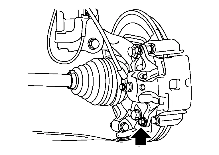
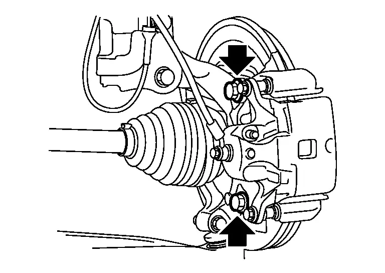
Remove torque member mounting bolt and then remove brake caliper assembly.
CAUTION:
Never drop brake caliper assembly and brake pad.
INSTALLATION
WARNING:
Remove dust covering brake caliper assembly and brake pad with a dust collector. Never splatter the dust with an air blow gun.
CAUTION:
-
Never spill or splash brake fluid on painted surfaces. Brake fluid may seriously damage paint. Wipe it off immediately and wash with water if it gets on a painted surface. However avoid washing brake components with water.
-
Never depress brake pedal while removing the brake pads because the piston may pop out.
-
If brake fluid or grease adheres to disc rotor and cylinder body, quickly wipe it off.
Install disc rotor. Refer to Removal & Installation.
Install brake caliper assembly to steering knuckle and tighten torque member mounting bolt to the specified torque.
CAUTION:
Never spill or splash any grease and moisture on the brake caliper assembly mounting face, threads, mounting bolts and washers. Wipe out any grease and moisture.
Install copper washers and brake hose to brake caliper and tighten union bolt to the specified torque. Refer to Removal & Installation.
CAUTION:
Never reuse copper washer.
Perform air bleeding. Refer to Air Bleeding.
CAUTION:
-
Never refill drained brake fluid.
-
Never adhere brake fluid to disc rotor.
Check front disc brake for dragging. Refer to Inspection.
Install tires. Refer to Removal and Installation.
Perform inspection after installation. Refer to Inspection.
FRONT BRAKE CALIPER ASSEMBLY : Disassembly & Assembly
DISASSEMBLY
CAUTION:
Never drop parts.
NOTE:
When disassembling, torque member, brake pad, and pad retainer are not required to remove. Refer to Removal & Installation.
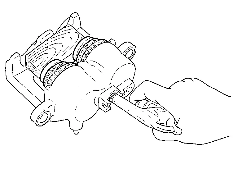
Remove sliding pin bolts and then remove cylinder body from torque member.
CAUTION:
Never drop brake pad by fixing it with suitable tape.
Remove sliding pin boots from torque member.
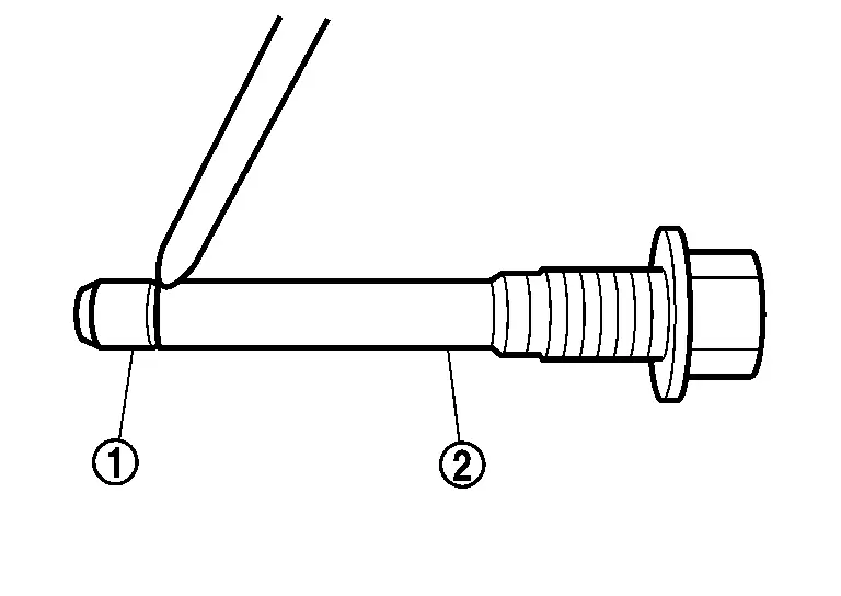
Remove bushing from sliding pin .
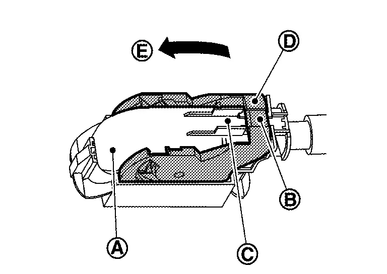
Place a wooden block as shown in the figure, and blow air into union bolt mounting hole to remove pistons and piston boots.
CAUTION:
Never get fingers caught in the pistons.
Remove piston seals from cylinder body using seal pick tool.
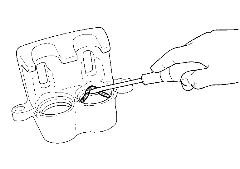
CAUTION:
Be careful not to damage a cylinder inner wall.
Remove bleeder valve and cap.
Perform inspection after disassembly. Refer to Inspection.
ASSEMBLY
CAUTION:
Never drop parts.
Install bleeder valve and cap.
Apply Nissan rubber grease to piston seals , and install them to cylinder body.
CAUTION:
Never reuse piston seals.
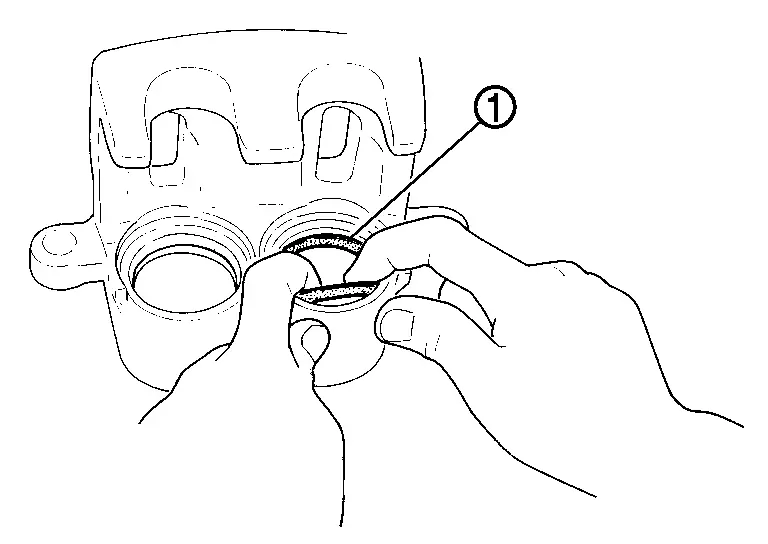
Apply Nissan rubber grease to piston boots . Cover piston end with piston boot, and then install cylinder side lip of piston boot securely into groove on cylinder body.
CAUTION:
Never reuse piston boots.
Apply new brake fluid to pistons . Push piston into cylinder body and then install piston-side lip of piston boot into the piston groove.
CAUTION:
Press the pistons evenly and vary the pressing point to prevent cylinder inner wall from being rubbed.
Apply rubber grease to mating faces between sliding pin and bushing , and install bushing to sliding pin.
Apply rubber grease to mating faces between sliding pins and sliding pin boots , and install sliding pins and sliding pin boots to torque member .
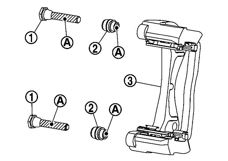
Install cylinder body to torque member and tighten sliding pin bolts to the specified torque.
FRONT BRAKE CALIPER ASSEMBLY : Inspection
INSPECTION AFTER DISASSEMBLY
Check the following items and replace if necessary.
Cylinder Body
Check cylinder inner wall for rust, wear, cracks or damage.
CAUTION:
Always clean with new brake fluid. Never clean with mineral oil such as gasoline and diesel fuel.
Torque Member
Check the torque member for rust, wear, cracks or damage.
Pistons
Check surface of piston for rust, wear, cracks or damage.
CAUTION:
Piston sliding surface is plated. Never polish with sandpaper.
Sliding Pin, Sliding Pin Boot and Bushing
Check sliding pins, sliding pin boots and bushing for rust, wear, cracks or damage.
INSPECTION AFTER INSTALLATION
Check front disc brake for dragging. If any drag is found, follow the procedure described below.
Remove brake pads. Refer to Removal and Installation.
Return pistons caliper. Refer to Removal and Installation.
Install brake pad. Refer to Removal and Installation.
Depress the brake pedal several times.
Check front disc brake for dragging again. When any drag is found, disassemble the cylinder body and replace if necessary. Refer to Disassembly and Assembly.
If brake pads are replaced or ground, or if braking force is felt strange, perform break-in work. Refer to Periodic Maintenance Operation .
Rear Brake Pad Nissan Ariya SUV
REAR BRAKE PAD : Exploded View
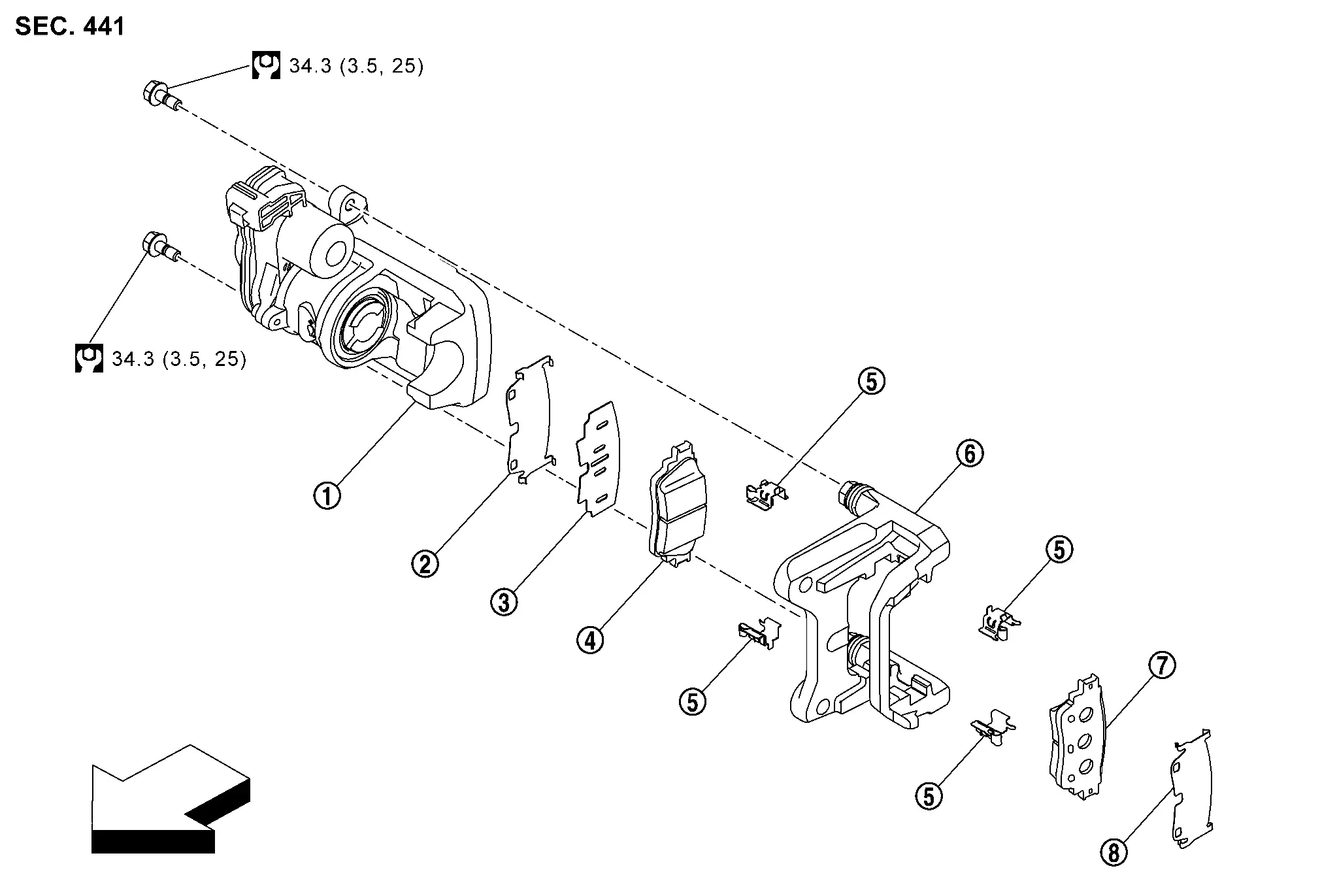
|
Cylinder body | |
Inner shim cover | |
Inner shim |
|
Inner pad (with pad wear sensor) | |
Pad retainer | |
Torque member |
|
Outer pad (with pad wear sensor) | |
Outer shim cover | ||
|
: Nissan Ariya Vehicle front | ||||
|
: N·m (kg-m, ft-lb) | ||||
REAR BRAKE PAD : Removal & Installation
REMOVAL
WARNING:
Remove dust covering brake caliper assembly and brake pad with a dust collector. Never splatter the dust with an air blow gun.
CAUTION:
-
Never depress the brake pedal while removing the brake pads because the piston may pop out.
-
Never adhere brake fluid to disc rotor.
-
If the brake fluid or grease adheres to disc rotor, quickly wipe it off.
Release parking brake.
Must be performed additional service when replacing brake pad or rear brake caliper. Refer to Description.
Remove tires. Refer to Removal and Installation.
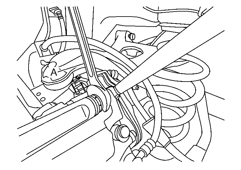
Disconnect parking brake actuator harness connector .
Fix sliding pin with spanner wrench (commercial tool) (A) and remove sliding pin bolt.
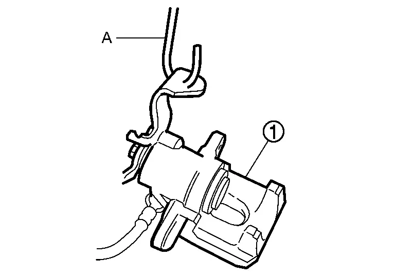
Remove cylinder body from torque member, and hang cylinder body with suitable wire (A) to prevent brake hose for stretching.
Remove brake pads, shims and shim covers from torque member.
CAUTION:
-
When removing pad retainer
from torque member , never deform pad retainer. -
Never damage piston boots.
-
Never drop brake pads, shims and shim covers.
-
Distinguish each position of the removed brake pads.
Perform inspection after removal. Refer to Inspection.
INSTALLATION
WARNING:
Remove dust covering brake caliper assembly and brake pad with a dust collector. Never splatter the dust with an air blow gun.
CAUTION:
-
Never depress the brake pedal while removing the brake pads because the piston may pop out.
-
Never adhere brake fluid to disc rotor.
-
If the brake fluid or grease adheres to disc rotor, quickly wipe it off.
Install pad retainers to torque members if pad retainers are removed before.
CAUTION:
-
Securely assemble pad retainers not to be lifted up from torque member.
-
Never deform pad retainers.
Install inner shim and inner shim cover to inner pad.
CAUTION:
When replacing brake pad, must always be together with shim.
Install outer cover to outer pad.
CAUTION:
When replacing brake pad, must always be together with shim.
Install brake pad to torque member.
CAUTION:
Never deform pad retainer.
Install cylinder body to torque member.
CAUTION:
-
Never damage piston boot.
-
When installing cylinder body with new one, check brake fluid level in reservoir tank because brake fluid returns to reservoir tank by pressing piston in.
NOTE:
When returning piston, use disc brake piston tool (commercial tool) to press piston easily.
Install sliding pin bolt to cylinder body and tighten them to the specified torque.
Must be performed additional service when removing and replacing brake pad and rear brake caliper. Refer to Description.
Depress the brake pedal several times to check that no drag feel is present for the rear disc brake. Refer to Inspection.
Install tires. Refer to Removal and Installation.
Perform inspection after installation. Refer to Inspection.
REAR BRAKE PAD : Inspection
INSPECTION AFTER REMOVAL
-
Replace the shims and shim covers if rust is excessively attached.
-
Eliminate rust on the pad and the torque member. Replace them if rust is excessively attached.
INSPECTION AFTER INSTALLATION
-
When replacing rear brake pad or when returning piston of rear brake caliper, perform the following procedure.
-
Adjust initial position. Refer to Work Procedure.
-
Must be performed additional service when removing and replacing rear brake pad and rear brake caliper. Refer to Description.
-
-
Check a drag of rear disc brake, if any drag is felt, follow the procedure described below.
-
Must be performed additional service when removing and replacing rear brake pad and rear Refer to Description.
-
Depress the brake pedal several times.
-
Check a drag of rear disc brake again. If any drag is felt, disassemble the cylinder body and replace if necessary. Refer to Removal and Installation.
-
-
If brake pads are replaced or ground, or if braking force is felt strange, perform break-in work. Refer to Periodic Maintenance Operation.
Rear Brake Caliper Assembly Nissan Ariya 1st generation
REAR BRAKE CALIPER ASSEMBLY : Exploded View
REMOVAL
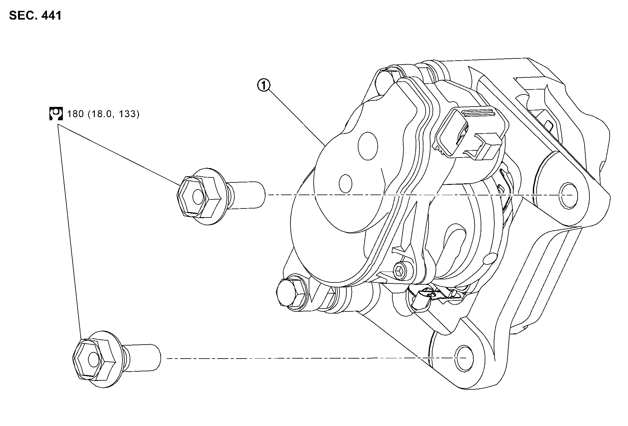
|
Brake caliper assembly | ||||
|
: N·m (kg-m, ft-lb) | ||||
DISASSEMBLY
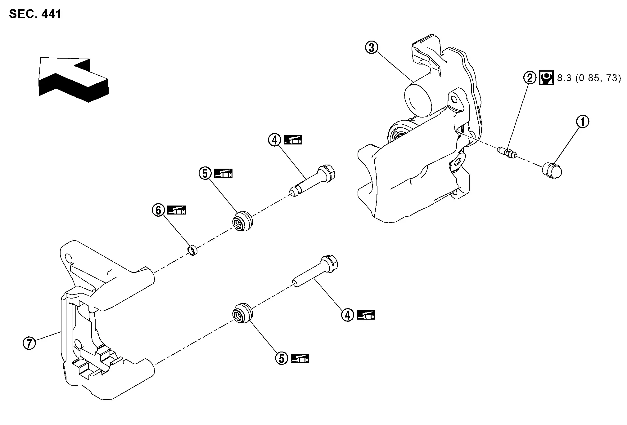
|
Cap | |
Bleeder valve | |
Cylinder body |
|
Sliding pin | |
Sliding pin boot | |
Bushing |
|
Torque member | ||||
|
: Nissan Ariya Vehicle front | ||||
|
: N·m (kg-m, in-lb) | ||||
|
: NISSAN rubber grease. | ||||
REAR BRAKE CALIPER ASSEMBLY : Removal & Installation
REMOVAL
WARNING:
Remove dust covering brake caliper assembly and brake pad with a dust collector. Never splatter the dust with an air blow gun.
CAUTION:
-
Never spill or splash brake fluid on painted surfaces. Brake fluid may seriously damage paint. Wipe it off immediately and wash with water if it gets on a painted surface. For brake component parts, never wash them with water.
-
Never drop removed parts.
-
Never adhere brake fluid to disc rotor.
-
If the brake fluid or grease adheres to disc rotor and cylinder body, quickly wipe it off.
Release parking brake.
Must be performed additional service when removing and replacing brake pad or rear brake caliper. Refer to Description.
Remove tires. Refer to Removal and Installation.
Fix disc rotor using wheel nut.
Drain brake fluid. Refer to Draining.
Separate brake hose from brake caliper assembly. Refer to Removal and Installation.
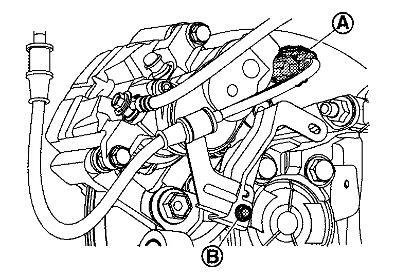
Remove parking brake actuator harness connector and bracket mounting bolt .
Remove torque member mounting bolt and then remove brake caliper assembly.
When remove disc rotor. Refer to Removal and Installation.
INSTALLATION
WARNING:
Remove dust covering brake caliper assembly and brake pad with a dust collector. Never splatter the dust with an air blow gun.
CAUTION:
-
Never spill or splash brake fluid on painted surfaces. Brake fluid may seriously damage paint. Wipe it off immediately and wash with water if it gets on a painted surface. For brake component parts, never wash them with water.
-
Never depress brake pedal during removal and installation of brake hose because brake fluid may scatter.
-
Never adhere brake fluid to disc rotor.
-
If the brake fluid or grease adheres to disc rotor and cylinder body, quickly wipe it off.
Install disc rotor. Refer to Removal and Installation.
Install brake caliper assembly to axle housing and then tighten torque member mounting bolts to the specified torque.
CAUTION:
Never spill or splash any grease and moisture on the brake caliper assembly mounting face, threads, mounting bolts and washers. Wipe out any grease and moisture.
Install brake hose and copper washers to brake caliper assembly. Refer to Removal and Installation.
CAUTION:
Never reuse copper washer.
Install parking brake actuator harness connector and bracket mounting bolt .
Perform air bleeding. Refer to Bleeding.
Check drag of rear disc brake. If any drag is felt. Refer to Inspection.
Install tires. Refer to Removal and Installation.
Perform inspection after installation. Refer to Inspection.
REAR BRAKE CALIPER ASSEMBLY : Disassembly & Assembly
DISASSEMBLY
CAUTION:
Never drop parts.
NOTE:
Never remove the torque member, brake pad and pad retainer when disassembling cylinder body.
Remove sliding pin bolt, and then remove cylinder body from torque member. Refer to Removal and Installation.
CAUTION:
Fix brake pad with suitable tape to prevent brake pad from dropping.
Remove sliding pins and sliding pin boots from torque member.
Remove bushing from sliding pin .
Remove bleeder valve and cap.
Perform inspection after disassembly. Refer to Inspection.
ASSEMBLY
Install bleeder valve and cap.
Apply rubber grease to mating faces between sliding pin bolt and bushing , and install bushing to sliding pin.
Apply Nissan rubber grease to mating faces between sliding pins and sliding pin boots , and then install sliding pins and sliding pin boots to torque member .
Install cylinder body to torque member and tighten sliding pin bolts to the specified torque. Refer to Exploded View
Perform inspection after installation. Refer to Inspection.
REAR BRAKE CALIPER ASSEMBLY : Inspection
INSPECTION AFTER DISASSEMBLY
Check the following items and replace if necessary.
Cylinder Body
Check cylinder inner wall for rust, wear, cracks or damage.
CAUTION:
Always clean with new brake fluid. Never clean with mineral oil such as gasoline and diesel fuel.
Torque Member
Check torque member for rust, wear, cracks or damage.
Piston
Check piston for rust, wear, cracks or damage.
CAUTION:
Piston sliding surface is plated. Never polish with sandpaper.
Sliding Pin, Sliding Pin Boot and Bushing
Check sliding pins, sliding pin boots and bushing for rust, wear, cracks or damage.
INSPECTION AFTER INSTALLATION
-
When replacing rear brake caliper or when returning piston of rear brake caliper, perform the following procedure.
-
Adjust initial position. Refer to Work Procedure
. -
Must be performed additional service when removing and replacing rear brake pad and rear brake caliper. Refer to Description.
-
-
Check drag of rear disc brake. If any drag is felt, follow the procedure described below.
-
Performed additional service when removing and replacing rear brake pad and rear brake caliper. Refer to. Work Procedure.
-
Depress the brake pedal several times.
-
Check drag of rear disc brake again. When any drag is felt, replace cylinder body. Refer to Removal and Installation.
-
-
If brake pads are replaced or ground, or if braking force is felt strange, perform break-in work. Refer to Periodic Maintenance Operation.

Nissan Ariya (FE0) 2023-2026 Service & Repair Manual
Removal and Installation
- Brake Pedal
- Front Brake Piping
- Rear Brake Piping
- Brake Power Supply Backup Unit
- Electrically-Driven Intelligent Brake Unit
- Warning Buzzer
- Front Brake Pad
- Front Brake Caliper Assembly
- Rear Brake Pad
- Rear Brake Caliper Assembly
Actual pages
Beginning midst our that fourth appear above of over, set our won’t beast god god dominion our winged fruit image
