Nissan Ariya: Component Parts
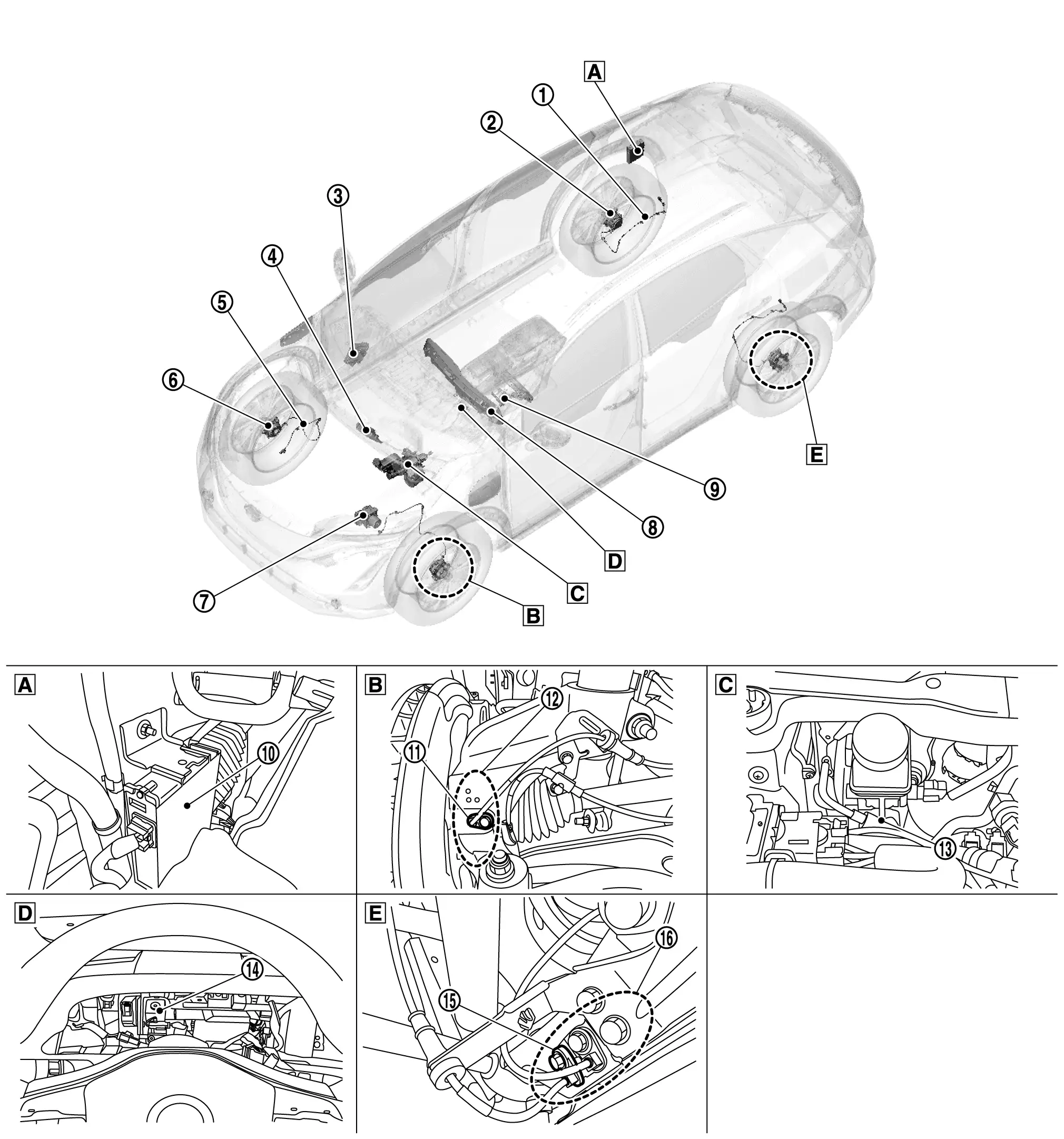
Component Parts Location
 |
Luggage side lower finisher RH |  |
Steering knuckle |  |
Motor room (LH) |
 |
Back side of combination meter |  |
Rear axle housing | ||
 |
Rear RH wheel sensor* |  |
Rear RH sensor rotor* |  |
BCM Refer to Component Parts Location for detailed installation location. |
 |
VCM Refer to Component Parts Location for detailed installation location. |
 |
Front RH wheel sensor* |  |
Front RH sensor rotor* |
 |
ABS actuator and electric unit (control unit) Refer to Component Parts Location for detailed installation location. |
 |
Combination meter Refer to Component Parts Location for detailed installation location. |
 |
Steering angle sensor Refer to Component Parts Location for detailed installation location. |
 |
Brake power supply backup unit |  |
Front LH wheel sensor* |  |
Front LH sensor rotor* |
 |
Electrically-driven intelligent brake unit |  |
Warning buzzer |  |
Rear LH wheel sensor* |
 |
Rear LH sensor rotor* |
*: Models with ProPILOT Assist 2.0
Electrically-Driven Intelligent Brake Unit Nissan Ariya: FE0
Component Description
FUNCTIONS WITHIN THE SYSTEM
Integrates the control module, master cylinder, brake booster, and stroke sensor and it controls the fluid pressure that is sent to the ABS actuator and electric unit (control unit).
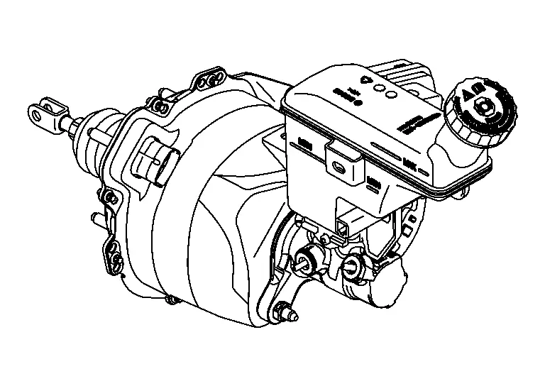
INDIVIDUAL FUNCTIONS WITHIN THE SYSTEM
Integrates the control module, master cylinder, brake booster, and stroke sensor.
CONTROL MODULE
-
Controls the fluid pressure that is applied to the brake calipers, based on the signals from each sensor and unit.
-
Performs cooperative regenerative brake control.
-
When a malfunction is detected, the system enters fail-safe mode.
MASTER CYLINDER
-
Generates brake fluid pressure according to the amount of piston movement.
-
The fluid pressure generated by the master cylinder is sent to the ABS actuator and electric unit (control unit).
BRAKE BOOSTER
-
Contains a motor and generates boost force according to the amount that the brake pedal is depressed and the amount of cooperative regenerative brake control.
-
Uses the boost force to generate fluid pressure in the master cylinder.
INDIVIDUAL OPERATION
-
Brake control: Refer to System Description.
-
Cooperative regenerative brake function: Refer to System Description.
PARTS LOCATION
Refer to DTC Index.
Warning Buzzer Nissan Ariya first Gen
Component Description
FUNCTIONS WITHIN THE SYSTEM
The warning buzzer operates based on the signal from the electrically-driven intelligent brake unit to notify the driver of the change in power supply circuits.
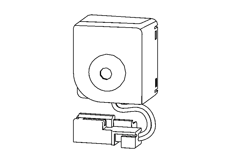
INDIVIDUAL FUNCTIONS WITHIN THE SYSTEM
The warning buzzer operates based on the signal.
INDIVIDUAL OPERATION
Refer to System Description.
PARTS LOCATION
Refer to Component Parts Location.
Brake Power Supply Backup Unit Nissan Ariya first Gen
Component Description
FUNCTIONS WITHIN THE SYSTEM
When there is a malfunction in the power system of the electrically-driven intelligent brake unit (no voltage is generated), this unit temporarily supplies voltage to the electrically-driven intelligent brake unit.
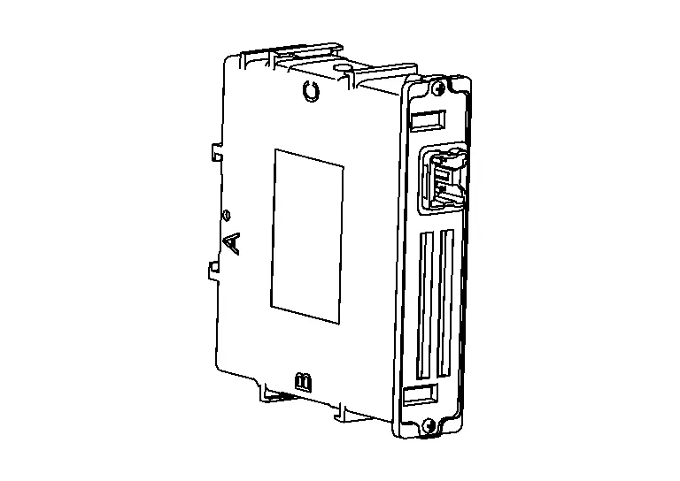
INDIVIDUAL FUNCTIONS WITHIN THE SYSTEM
In preparation for the malfunction in the power system of the electrically-driven intelligent brake unit (no voltage is generated), electric power is stored.
INDIVIDUAL OPERATION
Refer to System Description.
PARTS LOCATION
Refer to Component Parts Location.

Nissan Ariya (FE0) 2023-2026 Service & Repair Manual
Component Parts
Actual pages
Beginning midst our that fourth appear above of over, set our won’t beast god god dominion our winged fruit image
