Nissan Ariya: System Description
- Component Parts
- System. Cooperative Regenerative Brake Function
- Diagnosis System (electrically-Driven Intelligent Brake Unit). Consult Function
System. Cooperative Regenerative Brake Function Nissan Ariya 2026
System Description
-
An electrically-driven intelligent brake unit is a booster system that generates assist force by using an internal motor to operate a piston inside the master cylinder part.
-
Control module is integrated with electrically-driven intelligent brake unit.
-
When the brake pedal is depressed during driving, cooperative control of the braking force from the friction brake (regular brake) and the regenerative brake from the traction motor is used. In addition, cooperative control is performed in cooperation with electrically-driven intelligent brake unit and ABS actuator and electric unit (control unit).
-
Regenerative amount of the regenerative brake is executed by ABS actuator and electric unit (control unit), and brake pedal force control is performed by electrically-driven intelligent brake unit.
-
The system performs cooperative control of the regenerative brake and friction brake (same brake as in conventional Nissan Ariya vehicles) and enables highly efficient energy recovery.
-
The fluid pressure which is applied to each brake caliper is controlled according to the amount of traction motor regeneration.
-
The amount of brake pedal operation is detected by the stroke sensor, and sent to the control module of the electrically-driven intelligent brake unit.
-
Based on the commands from the control module of the electrically-driven intelligent brake unit, the motor inside the electrically-driven intelligent brake unit operates and presses the piston of master cylinder part.
-
Pressing the master cylinder piston, and brake fluid is sent to the ABS actuator and electric unit (control unit).
-
CONSULT can be used to diagnose the system diagnosis.
-
When there is a malfunction in the power system of the electrically-driven intelligent brake unit (no voltage is generated), voltage is temporarily supplied to the electrically-driven intelligent brake unit from the brake power supply backup unit. At the same time, the brake warning lamp and brake system warning lamp turn ON, and the warning buzzer sounds.
-
When a malfunction occurs in the electrically-driven intelligent brake unit, the VDC function performs control (boost operation). At the same time, the brake warning lamp and brake system warning lamp turn ON.
-
When a malfunction occurs in the PDM (Power Delivery Module) and 12V battery, the braking force is determined by the force pressing on the brake pedal (no boost operation). At the same time, the brake warning lamp and the brake system warning lamp turn ON.
-
When a malfunction occurs in the brake power supply backup unit, the brake system warning lamp turn ON.
-
When a malfunction occurs in the electrically-driven intelligent brake unit and in the VDC function, the braking force is determined by the force pressing on the brake pedal (no boost operation). At the same time, the brake warning lamp and brake system warning lamp turn ON.
-
When a malfunction occurs only electrically-driven intelligent brake unit, electrically-driven intelligent brake unit transmits to ABS actuator and electric unit (control unit) that electrically-driven intelligent brake unit is malfunction state.
-
When a malfunction occurs in the electrically-driven intelligent brake unit, the VDC function, and the power system, then cooperative regenerative brake control is not performed.
-
A fail-safe function is available and is activated when a system malfunction occurs. Refer to Fail-safe.
SYSTEM DIAGRAM
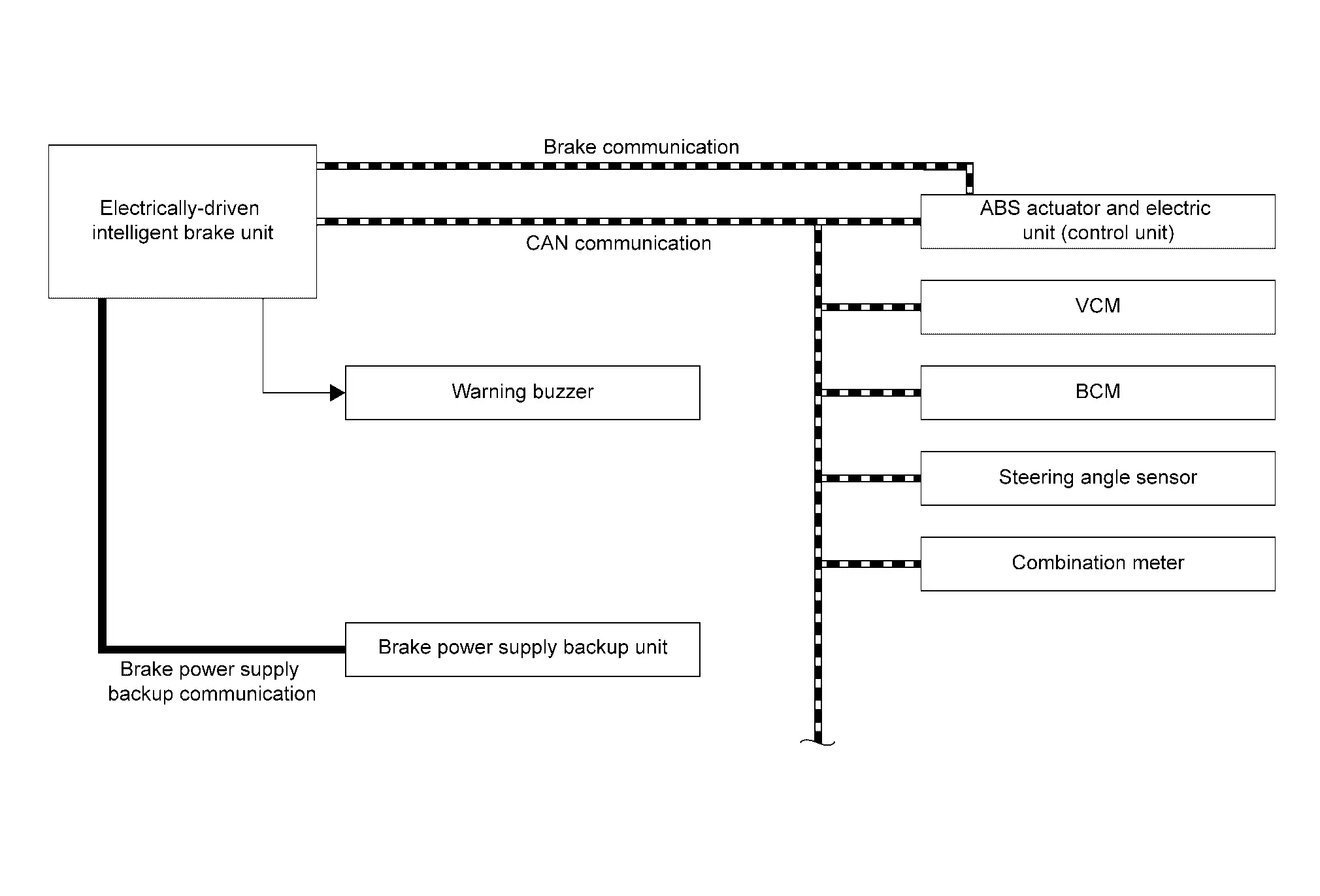
INPUT SIGNAL AND OUTPUT SIGNAL
Major signal transmission between each unit via communication lines is shown in the following table.
| Component | Function |
|---|---|
| Electrically-driven intelligent brake unit | Refer to Component Description. |
| Warning buzzer | Refer to Component Description. |
| Brake power supply backup unit | Refer to Component Description. |
| Steering angle sensor |
Mainly transmits the following signal to electrically-driven intelligent brake unit via CAN communication.
|
| Combination meter |
Mainly receives the following signals from ABS actuator electric unit (control unit) via electrically-driven intelligent brake unit via CAN communication.
|
| ABS actuator and electric unit (control unit) |
Mainly transmits the following signals to electrically-driven intelligent brake unit via CAN communication.
Mainly receives the following signals from electrically-driven intelligent brake unit via CAN communication.
|
| VCM |
Mainly transmits the following signals to electrically-driven intelligent brake unit and ABS actuator and electric unit (control unit) via CAN communication.
Mainly receives the following signal from electrically-driven intelligent brake unit and ABS actuator and electric unit (control unit) via CAN communication.
|
| BCM |
Mainly transmits the following signals to electrically-driven intelligent brake unit via CAN communication.
|
CONDITION FOR OPERATION OF THE WARNING LAMP AND THE WARNING BUZZER
Turns ON when power switch turns ON and turns OFF when the system is normal, for bulb check.
| Condition (status) | Brake warning lamp (red) | Brake system warning lamp (yellow) | Warning buzzer |
|---|---|---|---|
| Power switch OFF | OFF | OFF | OFF |
| For several seconds after the power switch is ON | ON | ON | OFF |
| Several seconds after power switch ON (when the system is in normal operation) | OFF | OFF | OFF |
| When the power supply to the electrically-driven intelligent brake unit is changed from the 12V battery to the brake power supply backup unit | ON | ON | ON |
| Brake power supply backup unit is malfunctioning | OFF | ON | OFF |
| Electrically-driven intelligent brake unit is malfunctioning | ON | ON | OFF |
| When brake fluid is less than the specified level (brake fluid level switch ON) | ON | OFF | OFF |
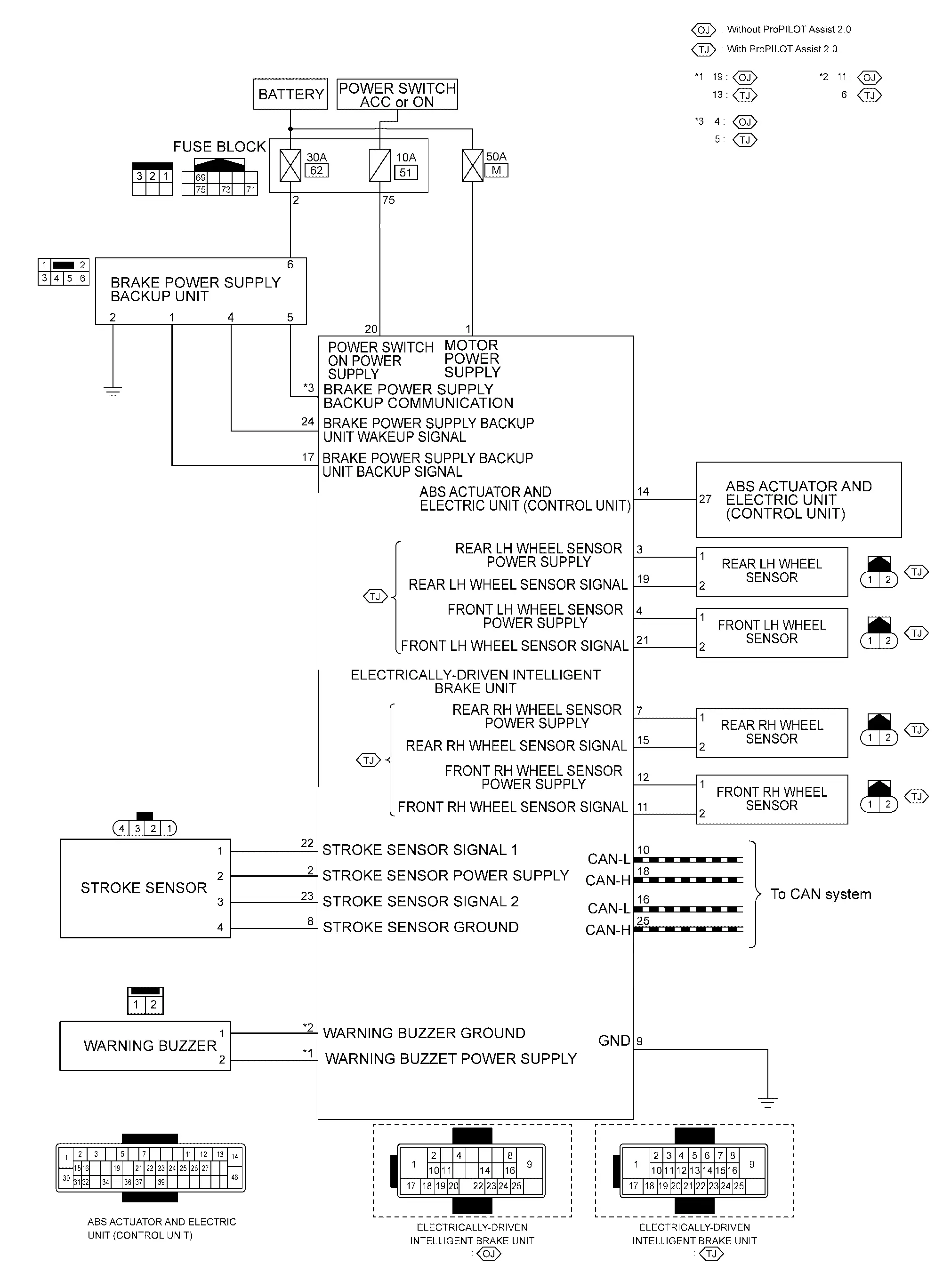
Circuit Diagram
Fail-safe
-
When there is a malfunction in the power system of the electrically-driven intelligent brake unit (no voltage is generated), voltage is temporarily supplied to the electrically-driven intelligent brake unit from the brake power supply backup unit. At the same time, the brake warning lamp and brake system warning lamp turn ON and the buzzer sounds.
-
When a malfunction occurs in the electrically-driven intelligent brake unit, the VDC function performs control (boost operation).
-
When a malfunction occurs in the PDM (Power Delivery Module) and 12V battery, the braking force is determined by the force pressing on the brake pedal (no boost operation). At the same time, brake warning lamp and the brake system warning lamp turn ON.
-
When a malfunction occurs in the brake power supply backup unit, the brake system warning lamp turn ON.
-
When a malfunction occurs in the electrically-driven intelligent brake unit and in the VDC function, the braking force is determined by the force pressing on the brake pedal (no boost operation). At the same time, the brake warning lamp and brake system warning lamp turn ON.
-
When a malfunction occurs in the electrically-driven intelligent brake unit, VDC function, and power system, cooperative regenerative brake control is not performed.
| DTC | Fail-safe condition |
|---|---|
| B14E0-02 |
The following functions are suspended.
|
| B14E0-09 | |
| B14E0-11 | |
| B14E0-12 | |
| B14E0-13 | |
| B14E0-1C | |
| B14E0-38 | |
| B14E0-4A | |
| B14E0-64 | |
| B14E1-02 | |
| B14E1-09 | |
| B14E1-11 | |
| B14E1-12 | |
| B14E1-13 | |
| B14E1-1C | |
| B14E1-38 | |
| B14E1-4A | |
| B14E1-64 | |
| B14E2-02 | |
| B14E2-09 | |
| B14E2-11 | |
| B14E2-12 | |
| B14E2-13 | |
| B14E2-1C | |
| B14E2-38 | |
| B14E2-4A | |
| B14E2-64 | |
| B14E3-02 | |
| B14E3-09 | |
| B14E3-11 | |
| B14E3-12 | |
| B14E3-13 | |
| B14E3-1C | |
| B14E3-38 | |
| B14E3-4A | |
| B14E3-64 | |
| B14E4-64 | |
| B14E5-64 | Normal control |
| B14E5-92 | |
| B14E6-85 | |
| B14E6-92 | |
| C18D0-01 |
The following functions are suspended.
|
| C18D1-09 | |
| C18D2-12 | |
| C18D3-14 | |
| C18D4-14 | |
| C18D5-09 | |
| C18D6-09 | |
| C18D7-09 | |
| C18D8-09 | |
| C18D9-09 | |
| C18DA-09 | |
| C18DB-09 | |
| C18DC-09 | |
| C18DD-09 | |
| C18DE-82 | |
| C18DE-83 | |
| C18DE-87 | |
| C18E1-04 | Normal control |
| C18E1-07 |
The following functions are suspended.
|
| C18E1-18 | |
| C18E1-19 | |
| C18E1-49 | |
| C18E1-4B | |
| C18E3-86 | |
| C18E4-88 | |
| C18E5-88 | |
| C18E6-49 | |
| C18E7-13 | Normal control |
| C18E7-16 |
The following functions are suspended.
|
| C18E7-17 | |
| C18E7-1C | |
| C18E9-01 | |
| C18E9-04 | |
| C18E9-44 | |
| C18E9-45 | |
| C18E9-46 | |
| C18E9-47 | |
| C18E9-48 | |
| C18E9-49 | |
| C18E9-96 | |
| C18EA-01 | |
| C18EB-01 | |
| C18EC-01 |
The following functions are suspended.
|
| C18EC-04 | |
| C18EC-11 | |
| C18EC-12 | |
| C18EC-13 | |
| C18EC-14 | |
| C18EC-15 | |
| C18EC-1F | |
| C18ED-04 | |
| C18EE-01 | |
| C18EE-04 | |
| C18EE-64 | |
| C18EE-87 | |
| C18EE-96 | |
| C18EF-16 | |
| C18EF-17 | |
| C18EF-96 | |
| C18F1-08 | |
| C18F3-04 | |
| C18F3-4B | |
| C18F4-86 | Normal control |
| C18F5-08 | |
| C18F6-08 | |
| C18F7-08 |
The following functions are suspended.
|
| C18F7-86 | |
| C18F8-08 | Normal control |
| C18F8-86 | |
| C18F9-02 | |
| C18FA-44 |
The following functions are suspended.
|
| C18FA-46 | Normal control |
| C18FC-18 |
The following functions are suspended.
|
| C18FC-19 | |
| C18FD-18 | |
| C18FD-19 | |
| C18FE-29 | |
| U1FA1-86 | Normal control |
| U2140-87 | |
| U2143-87 | |
| U2148-87 |
The following functions are suspended.
|
| U214F-87 | Normal control |
| U2240-87 | |
| U2243-87 | |
| U2248-87 |
The following functions are suspended.
|
| U224F-87 | Normal control |
| U2252-87 | |
| U225B-87 |
Warning / Indicator / Chime List
| Name | Design | Layout / Function |
|---|---|---|
| Brake warning lamp |  |
For layout: Refer to Design. |
| For function: Refer to Brake Warning Lamp. | ||
| Brake system warning lamp |  |
For layout: Refer to Design. |
| For function: Refer to Brake System Warning Lamp. |
| Name | Design | Layout / Function |
|---|---|---|
| Brake warning lamp | |
For layout: Refer to Design. |
| For function: Refer to Brake Warning Lamp. | ||
| Brake system warning lamp |  |
For layout: Refer to Design. |
| For function: Refer to Brake System Warning Lamp. |
System Description
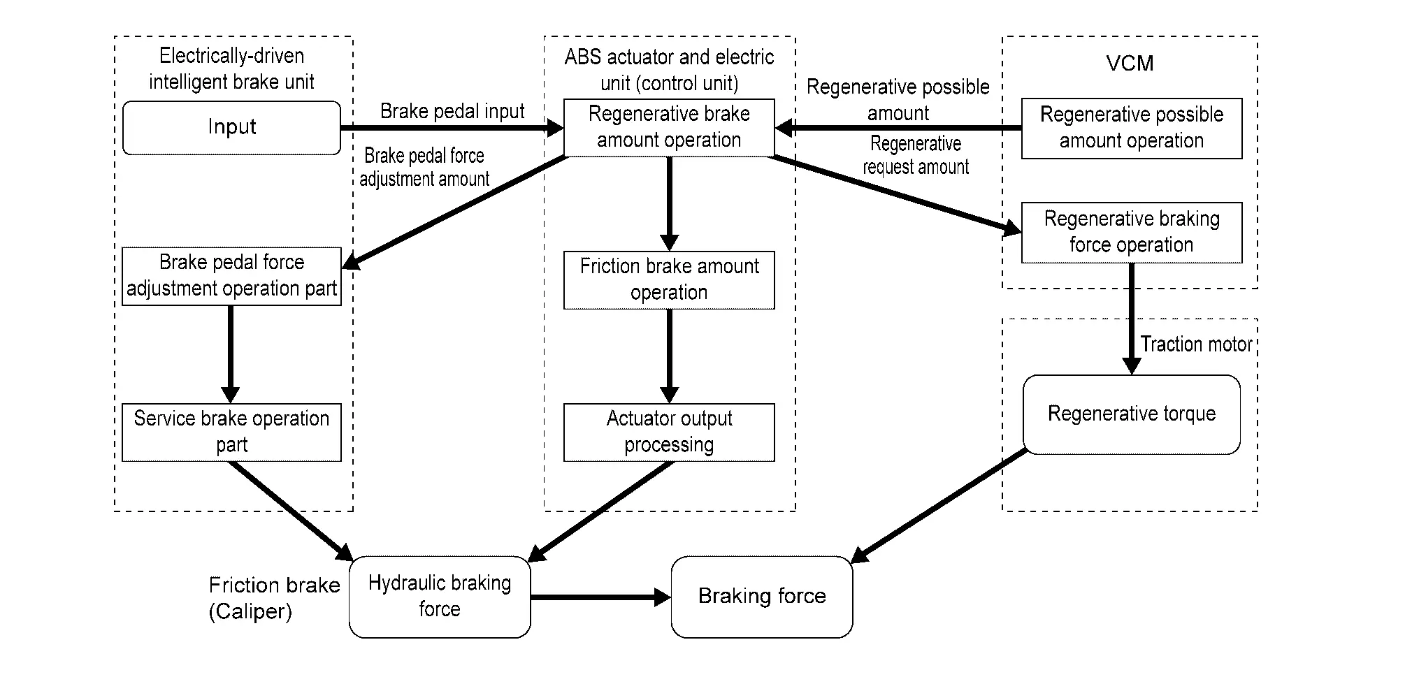
COOPERATIVE REGENERATIVE BRAKE CONTROL
-
A regenerative brake drives the traction motor to act as an alternator, and converts the kinetic energy produced by rotation of the tires into electrical energy. The converted electrical energy charges the Li-ion battery.
-
When the brakes are operated (during driving), the electrically-driven intelligent brake unit calculates the required braking force based on the input value from the stroke sensor (indicating the amount of brake pedal operation), and it sends the result to the VCM. At the same time, it calculates the hydraulic braking force needed to produce the required braking force.
-
The VCM calculates the regenerative braking force needed to produce the required braking force, and sends the result to the electrically-driven intelligent brake unit. At the same time, the traction motor inverter uses the traction motor to perform regenerative braking.
-
The electrically-driven intelligent brake unit and ABS actuator and electric unit (control unit) calculates the hydraulic braking force again based on the regenerative braking force result from the VCM and the calculated result for hydraulic braking force.
-
Electrically-driven intelligent brake unit controls brake pedal force according to calculated amount of regenerative braking torque.
 NOTE:
NOTE:
The fluid pressure signal applied to the master cylinder part is transmits the electrically-driven intelligent brake unit from ABS actuator and electric unit (control unit) via brake communication (CAN communication).
-
The fluid pressure generated by the master cylinder is sent to each brake.
-
When the cooperative regenerative brake is operating, the motor inside the electrically-driven intelligent brake unit moves the piston of master cylinder part according to the amount of regeneration.
-
Moving the piston of master cylinder part increases the fluid pressure applied to the ABS actuator and electric unit (control unit). (The brake pedal stroke does not change.)
-
When brake control is stopped (immediately before Nissan Ariya vehicle stop or while vehicle is stopped), cooperative regenerative brake control is not performed.
SYSTEM DIAGRAM
INPUT SIGNAL AND OUTPUT SIGNAL
Major signal transmission between each unit via communication lines is shown in the following table.
| Component | Function |
|---|---|
| Electrically-driven intelligent brake unit | Refer to Component Description. |
| Warning buzzer | Refer to Component Description. |
| Brake power supply backup unit | Refer to Component Description. |
| Steering angle sensor |
Mainly transmits the following signal to electrically-driven intelligent brake unit via CAN communication.
|
| Combination meter |
Mainly receives the following signals from electrically-driven intelligent brake unit via ABS actuator electric unit (control unit) via CAN communication.
|
| ABS actuator and electric unit (control unit) |
Mainly transmits the following signals to electrically-driven intelligent brake unit via CAN communication.
Mainly receives the following signals from electrically-driven intelligent brake unit via CAN communication.
|
| VCM |
Mainly transmits the following signals to electrically-driven intelligent brake unit via CAN communication.
Mainly receives the following signal from electrically-driven intelligent brake unit via CAN communication.
|
| BCM |
Mainly transmits the following signals to electrically-driven intelligent brake unit via CAN communication.
|
Diagnosis System (electrically-Driven Intelligent Brake Unit). Consult Function Nissan Ariya 2023
Diagnosis Description
APPLICATION ITEM
CONSULT can display each diagnostic item using the diagnostic test modes as follows.
| Diagnosis mode | Note |
|---|---|
| Self Diagnostic Result | Display DTC which electrically-driven intelligent brake unit memorizes |
| Data monitor | Displays electrically-driven intelligent brake unit input/output data in real time |
| Active test | Enables an operational check of a load by transmitting a driving signal from the electrically-driven intelligent brake unit to the load |
| ECU Identification | Displays electrically-driven intelligent brake unit part number |
| Replace ECU | Write the Nissan Ariya vehicle specification when replacing electrically-driven intelligent brake unit |
SELF DIAGNOSTIC RESULT
Refer to DTC Index.
When “CRNT” is displayed on self-diagnosis result
-
The system is presently malfunctioning.
When “PAST” is displayed on self-diagnosis result
-
System malfunction in the past is detected, but the system is presently normal.
Freeze frame data (FFD)
When DTC is detected, a vehicle state shown below is recorded and displayed on CONSULT.
| Item | Unit | Description |
|---|---|---|
| Error code | — | Displays but not used. |
| ODO/TRIP meter | km | Displays the total mileage (Odometer value) of the moment a particular. |
| DTC count | — | Displays the number of times DTC is detected. |
DATA MONITOR
NOTE:
-
The following table includes information (items) inapplicable to this Nissan Ariya vehicle. For information (items) applicable to this vehicle, refer to CONSULT display items.
-
Perform all self-diagnosis and delete stored DTC after execute Data monitor.
| Item | Unit | Note |
|---|---|---|
| Input rod position | mm | Displays the input rod position. |
| Output rod position | mm | Displays the output rod position. |
| Temperature 1 | ℃ | Display the control unit temperature of electrically-driven intelligent brake unit. |
| Temperature 2 | ℃ | Display the control unit temperature of electrically-driven intelligent brake unit. |
| Battery voltage | V | Displays the 12V battert power supply voltage value applied to electrically-driven intelligent brake unit. |
| Control module voltage | mV | Displays the power switch ON power supply voltage value applied to electrically-driven intelligent brake unit. |
| Stroke sensor | V | Displays the output voltage of stroke sensor. |
| Front LH wheel speed | — | Displays but not used. |
| Front RH wheel speed | — | Displays but not used. |
| Rear LH wheel speed | — | Displays but not used. |
| Rear RH wheel speed | — | Displays but not used. |
| Nissan Ariya Vehicle speed 1 | — | Displays but not used. |
| Forward / backward judgment | — | Displays but not used. |
| Backup power supply volt | V | Displays the power supply voltage value applied to brake power supply backup unit. |
| Odometer | m | Displays the mileage. |
| Wheel speed 1 | kph | Displays the wheel speed of drive wheel. |
| Wheel speed 2 | kph | Displys the wheel speed of passive wheel. |
| Brake fluid pressure | Mpa | Displays the brake fluid pressure. |
| External brake request | 1 / 2 / 3 / 4 | Displays the request status of except driver brake. |
ACTIVE TEST
The active test is used to determine and identify details of a malfunction, based on self-diagnosis test result and data obtained in the Data monitor. In response to instructions from CONSULT, instead of those from electrically-driven intelligent brake unit on the Nissan Ariya vehicle, a drive signal is sent to the actuator to check its operation.
CAUTION:
-
Never perform Active test while driving the vehicle.
-
Always bleed air from brake system before active test.
-
Never perform active test when system is malfunctioning.
NOTE:
-
When performing active test again after “TEST IS STOPPED” is displayed, select “BACK”.
-
Brake warning lamp and brake system warning lamp may turn ON during active test. This is not a malfunction.
-
Perform all self-diagnosis and delete stored DTC after execute Active test.
Warning Buzzer
| Item | Note |
|---|---|
| Buzzer | Activate the buzzer. |
ECU IDENTIFICATION
Electrically-driven intelligent brake unit part number can be read.
REPLACE ECU
Write the vehicle specification when replacing electrically-driven intelligent brake unit.

Nissan Ariya (FE0) 2023-2026 Service & Repair Manual
System Description
- Component Parts
- System. Cooperative Regenerative Brake Function
- Diagnosis System (electrically-Driven Intelligent Brake Unit). Consult Function
Actual pages
Beginning midst our that fourth appear above of over, set our won’t beast god god dominion our winged fruit image
