Nissan Ariya: Component Parts
- Brake Control System
- Abs Actuator and Electric Unit (control Unit)
- Wheel Sensor and Sensor Rotor
- Steering Angle Sensor
- Brake Fluid Level Switch
Brake Control System Nissan Ariya 1st generation
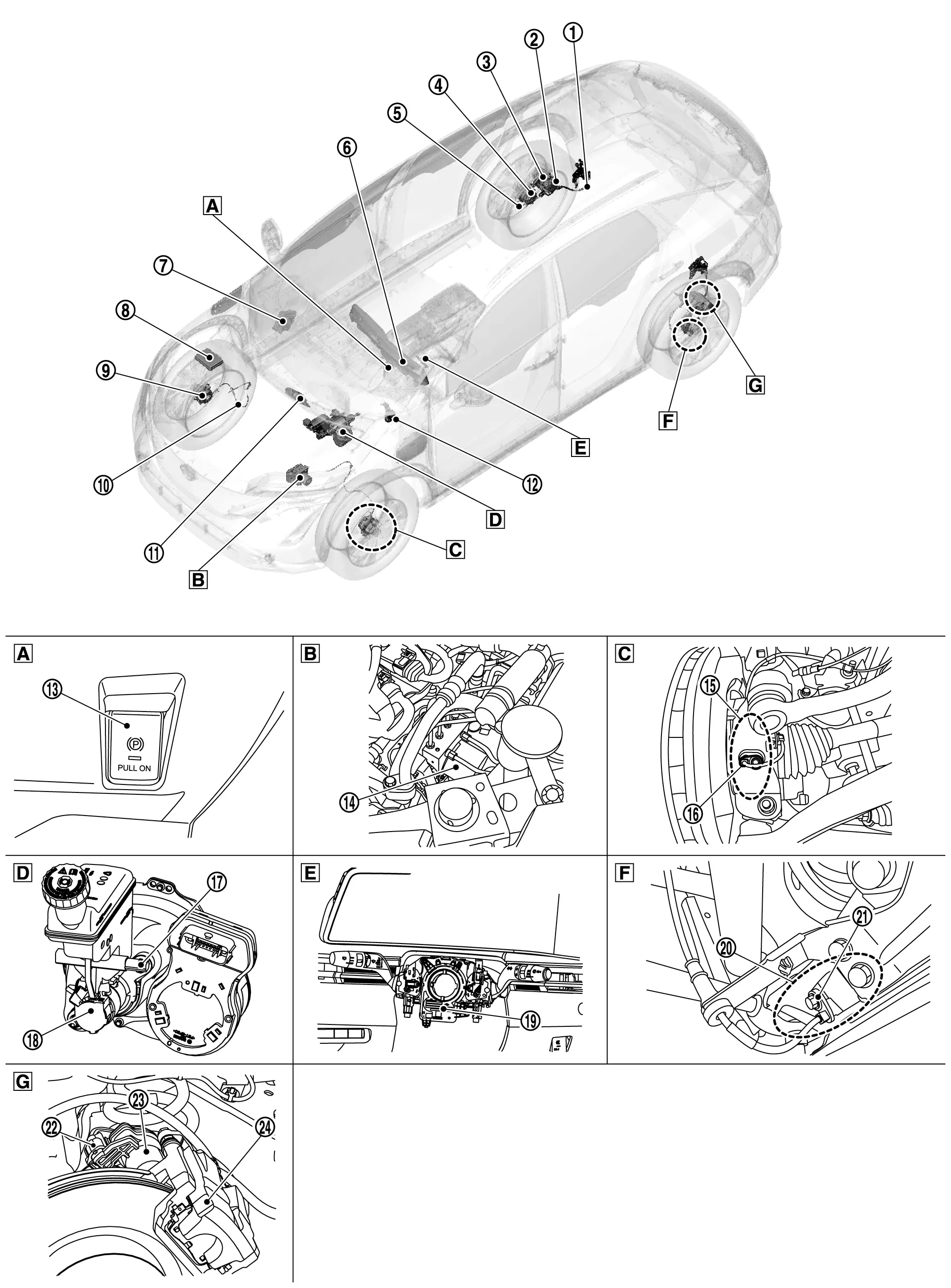
Component Parts Location
 |
Instrument lower panel |  |
Motor room (LH side) |  |
Steering knuckle |
 |
Motor room (LH side) |  |
Back of spiral cable assembly |  |
Rear axle housing |
 |
Rear brake caliper assembly (LH side) |
 |
Parking brake actuator harness (RH) |  |
Parking brake actuator (RH) |  |
Rear brake caliper assembly (RH) |
 |
Rear RH sensor rotor |  |
Rear RH wheel sensor |  |
Combination meter Refer to Component Parts Location for detailed installation location. |
 |
BCM Refer to Component Parts Location for detailed installation location. |
 |
IPDM E/R Refer to Component Parts Location for detailed installation location. |
 |
Front RH sensor rotor |
 |
Front RH wheel sensor |  |
VCM Refer to Component Parts Location for detailed installation location. |
 |
Chassis control module Refer to Component Parts Location for detailed installation location. |
 |
Parking brake switch |  |
ABS actuator and electric unit (control unit) |  |
Front LH sensor rotor |
 |
Front LH wheel sensor |  |
Brake fluid level switch |  |
Electrically-driven intelligent brake unit |
 |
Steering angle sensor |  |
Rear LH sensor rotor |  |
Rear LH wheel sensor |
 |
Parking brake actuator harness (LH) |  |
Parking brake actuator (LH) |  |
Rear brake caliper assembly (LH) |
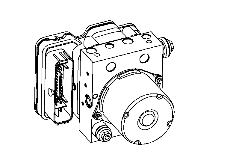
Abs Actuator and Electric Unit (control Unit) Nissan Ariya: FE0
Component Description
FUNCTIONS WITHIN THE SYSTEM
Electric unit (control unit) is integrated with actuator and comprehensively controls VDC function, TCS function, ABS function, EBD function, hill start assist function, brake limited slip differential (BLSD) function, brake assist function, brake force distribution function, cooperative regenerative brake function, and electric parking brake function.
ELECTRIC UNIT (CONTROL UNIT)
-
Brake fluid pressure are controlled according to signals from each sensor.
-
Parking brake actuator are controlled according to parking brake switch and signals from each control unit.
-
If malfunction is detected, the system enters fail-safe mode.
ACTUATOR
The following components are integrated with ABS actuator.
Pump
-
Returns the brake fluid reserved in reservoir to master cylinder by reducing pressure.
-
Pressure the brake fluid and send.
Motor
Activates the pump according to signals from electric unit (control unit).
Motor Relay
Operates the motor ON/OFF according to signals from electric unit (control unit).
Actuator Relay
Operates each valve ON/OFF according to signals from electric unit (control unit).
ABS In Valve
Switches the fluid pressure line to increase or hold according to signals from electric unit (control unit).
 NOTE:
NOTE:
Valve is a solenoid valve.
ABS Out Valve
Switches the fluid pressure line to increase, hold or decrease according to signals from electric unit (control unit).
NOTE:
Valve is a solenoid valve.
Cut Valve 1, Cut Valve 2
Shuts off the brake line from electrically-driven intelligent brake unit to each brake to according signal from control unit.
NOTE:
Valve is a solenoid valve.
Suction Valve 1, Suction Valve 2
Opens the brake line from electrically-driven intelligent brake unit to pump to according signal from control unit.
NOTE:
Valve is a solenoid valve.
Inlet Valve
Brake fluid sucked from the reservoir by the pump does not backflow.
NOTE:
Valve is a solenoid valve.
Outlet Valve
Brake fluid discharged from the pump does not backflow.
NOTE:
Valve is a solenoid valve.
Return Check Valve
Returns the brake fluid from brake caliper to electrically-driven intelligent brake unit by bypassing orifice of each valve when brake is released.
Reservoir
Temporarily reserves the brake fluid drained from brake caliper, so that pressure efficiently decreases when decreasing pressure of brake caliper.
Yaw Rate/Side/Decel G Sensor
Calculates the following information that affects the vehicle, and transmits a signal to electric unit (control unit). [Yaw rate/side/decel G sensor is integrated in ABS actuator and electric unit (control unit).]
-
Vehicle rotation angular velocity (yaw rate signal)
-
Vehicle lateral acceleration (side G signal) and longitudinal acceleration (decel G signal)
Pressure Sensor
Detects the brake fluid pressure and transmits signal to electric unit (control unit). [Pressure sensor is integrated in ABS actuator and electric unit (control unit).]
INDIVIDUAL OPERATION
-
Brake fluid pressure and traction motor are controlled according to signals from each sensor.
-
Parking brake actuator are controlled according to parking brake switch and signals from each control unit.
-
If malfunction is detected, the system enters fail-safe mode.
PARTS LOCATION
Refer to Component Parts Location.
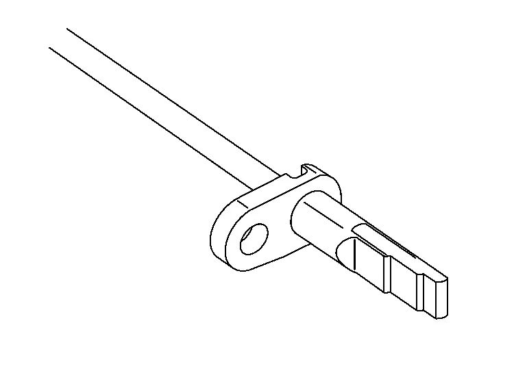
Wheel Sensor and Sensor Rotor Nissan Ariya
Component Description
FUNCTIONS WITHIN THE SYSTEM
Wheel sensor and sensor rotor detect each wheel speed. And wheel sensor inputs wheel speed signal to ABS actuator and electric unit (control unit).
INDIVIDUAL FUNCTIONS WITHIN THE SYSTEM
Wheel Sensor
The wheel sensor reads a magnetic field change.
INDIVIDUAL OPERATION
-
Downsize and weight reduction is aimed. IC for detection portion and magnet for sensor rotor are adopted.
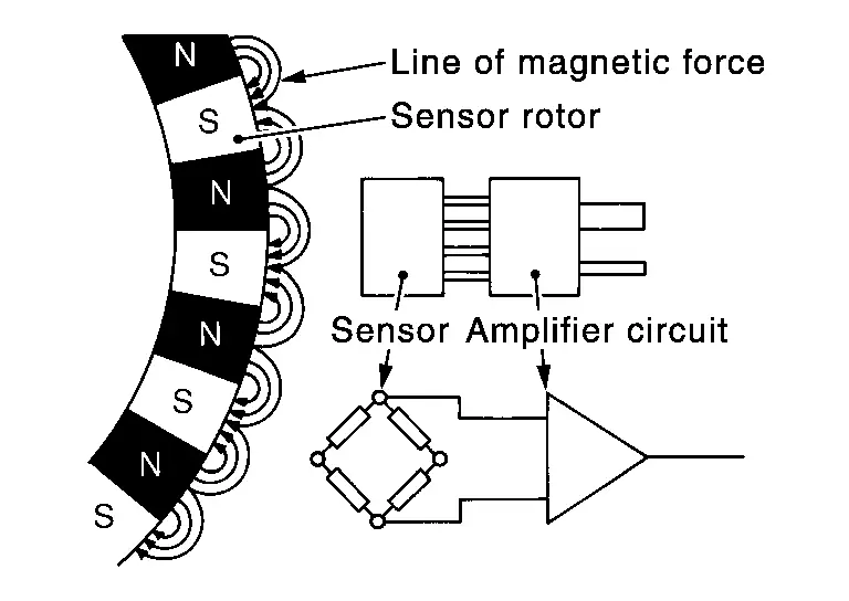
When sensor rotor rotates, magnetic field changes. Magnetic field change is converted to current signals (rectangular wave) and is transmitted to ABS actuator and electric unit (control unit). Change of magnetic field is proportional to wheel speed.
PARTS LOCATION
Refer to Component Parts Location.
Steering Angle Sensor Nissan Ariya 1st generation
Component Description
FUNCTIONS WITHIN THE SYSTEM
Steering angle sensor transmits steering angle sensor signal to ABS actuator and electric unit (control unit) via CAN communication.
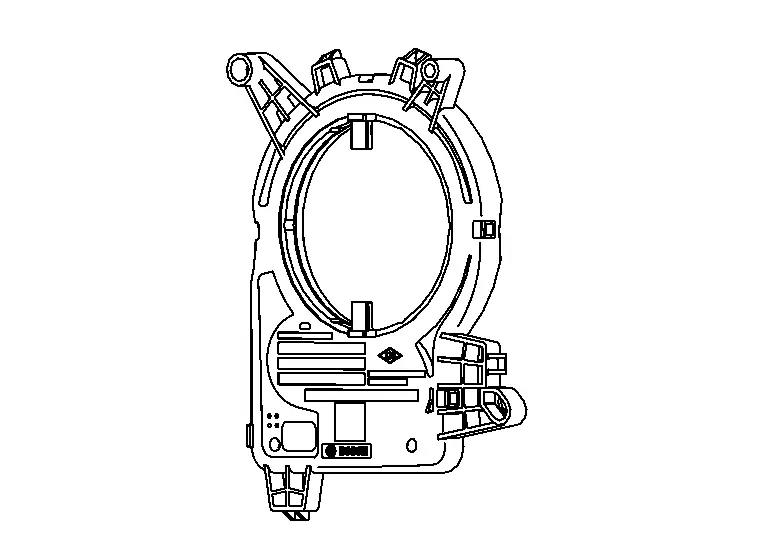
INDIVIDUAL FUNCTIONS WITHIN THE SYSTEM
Steering angle sensor detects the following status.
-
Steering wheel rotation amount
-
Steering wheel rotation angular velocity
-
Steering wheel rotation direction
VIDUAL OPERATION
The sensor converts the rotation amount, rotation angular velocity and rotation direction of the steering wheel as the steering angle sensor signal.
PARTS LOCATION
Refer to Component Parts Location.
Brake Fluid Level Switch Nissan Ariya 2023
Component Description
FUNCTIONS WITHIN THE SYSTEM
Detects the brake fluid level in reservoir tank and transmits converted electric signal from combination meter to ABS actuator and electric unit (control unit) via CAN communication, when brake fluid level is the specified level or less.
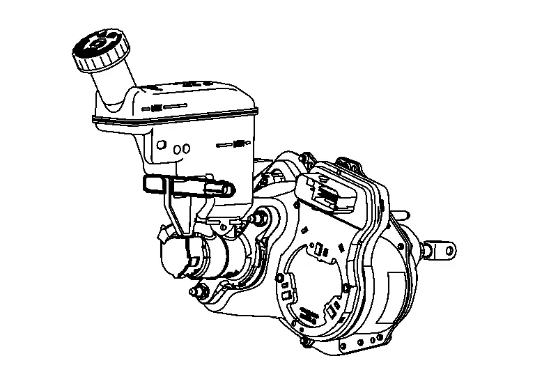
INDIVIDUAL FUNCTIONS WITHIN THE SYSTEM
Brake fluid level switch detects the brake fluid level in reservoir tank.
INDIVIDUAL OPERATION
-
The switch is turned ON when brake fluid level is the specified level or less.
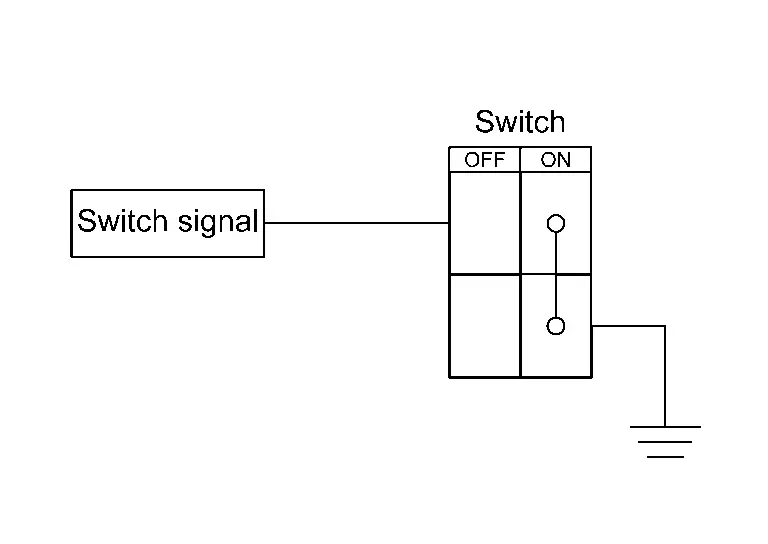
-
Ground is supplied as the switch signal to the control unit when the switch is turned ON.
PARTS LOCATION
Refer to Component Parts Location.

Nissan Ariya (FE0) 2023-2026 Service & Repair Manual
Component Parts
- Brake Control System
- Abs Actuator and Electric Unit (control Unit)
- Wheel Sensor and Sensor Rotor
- Steering Angle Sensor
- Brake Fluid Level Switch
Actual pages
Beginning midst our that fourth appear above of over, set our won’t beast god god dominion our winged fruit image
