Nissan Ariya: Component Parts
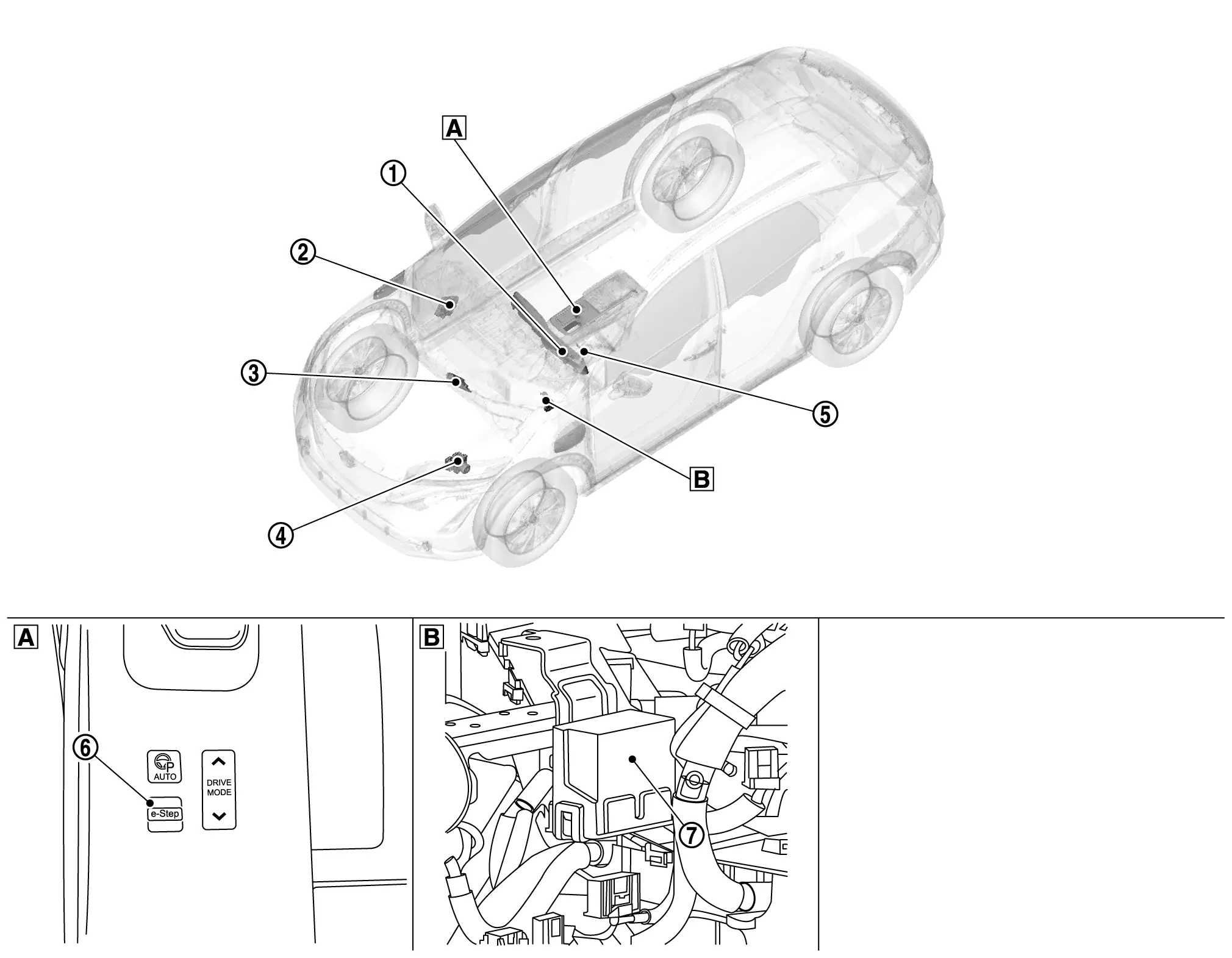
Component Parts Location
 |
Center console finisher |  |
Back of instrument lower panel (RH side) |
 |
Combination meter Refer to Component Parts Location. for detailed installation location. |
 |
BCM Refer to Component Parts Location. for detailed installation location. |
 |
VCM Refer to Component Parts Location. for detailed installation location. |
 |
ABS actuator and electric unit (control unit) Refer to Component Parts Location. for detailed installation location. |
 |
Steering angle sensor Refer to Component Parts Location. for detailed installation location. |
 |
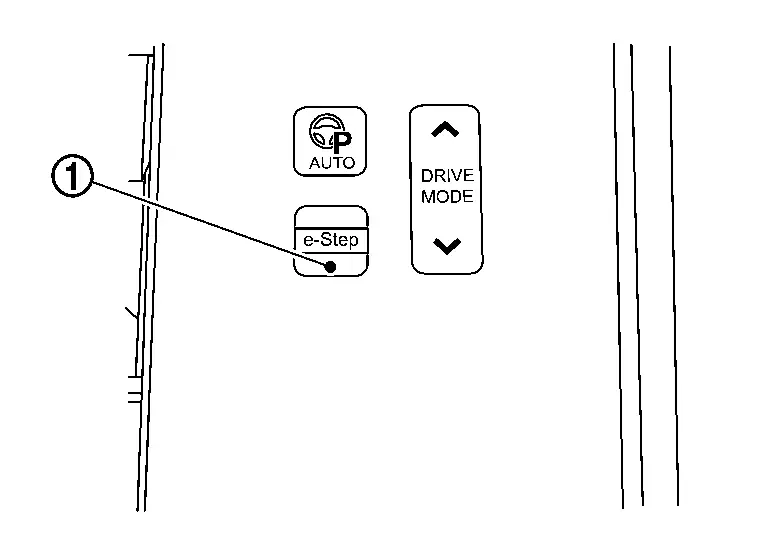
e-Step switch |
 |
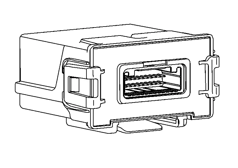
Chassis control module |
Chassis Control Module Nissan Ariya 1st generation
Component Description
FUNCTIONS WITHIN THE SYSTEM
Chassis control module controls automatic brake hold function and e-Step function according to the signals from each sensor, each switch and each control unit.
INDIVIDUAL FUNCTIONS WITHIN THE SYSTEM
-
Receives the signals required to activate the automatic brake hold function and e-Step function from each control unit.
-
Transmits the signals required to activate the automatic brake hold function and e-Step function to each control unit.
PARTS LOCATION
Refer to Component Parts Location.
E-Step Switch Nissan Ariya 1st generation
Component Description
FUNCTIONS WITHIN THE SYSTEM
-
The e-Step function to be activated or deactivated each time the e-Step switch is pushed.
-
Setting state of function is displayed in the information display on the combination meter. Refer to System Description.
INDIVIDUAL FUNCTIONS WITHIN THE SYSTEM
The e-Step status signal is transmitted to the VCM with driver’s switch operation.
INDIVIDUAL OPERATION
The driver touches the switch to switch between the operation state and the non-operation state of the e-Step function.
PARTS LOCATION
Refer to Component Parts Location.

Nissan Ariya (FE0) 2023-2026 Service & Repair Manual
Component Parts
Actual pages
Beginning midst our that fourth appear above of over, set our won’t beast god god dominion our winged fruit image
