Nissan Ariya: Component Parts
Rear Traction Motor System Nissan Ariya 2023
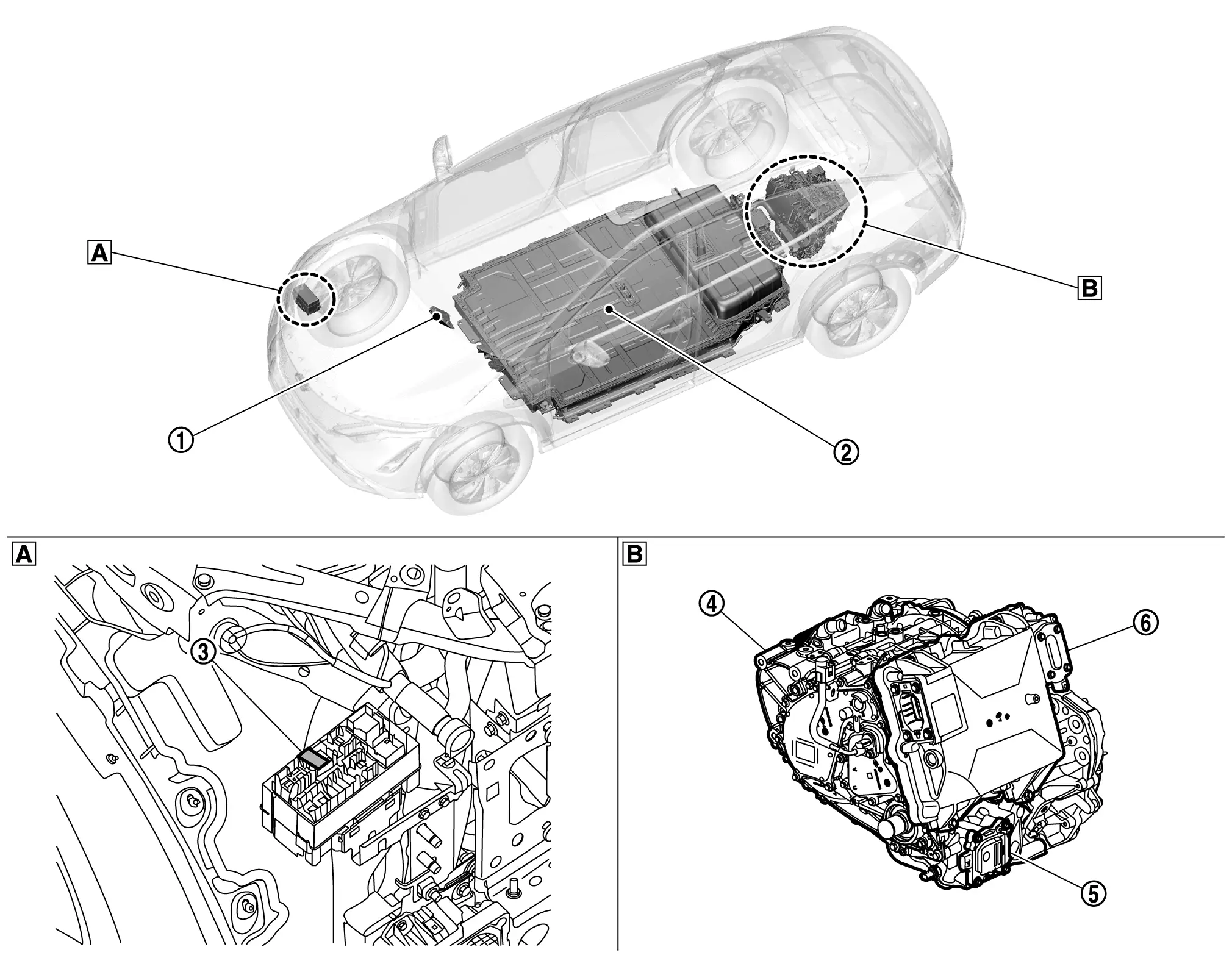
Component Parts Location
 |
VCM Refer to Component Parts Location. |
 |
LBC (Li-ion battery controller) Refer to Component Parts Location (66kWh Li-ion battery models), Component Parts Location (91kWh Li-ion battery models). |
 |
Traction motor oil pump relay |
 |
Rear traction motor |  |
Rear traction motor oil pump |  |
Inverter (rear) |
 |
Right back side of front bumper |  |
Rear suspension member, upper |
Inverter (rear) Nissan Ariya SUV
Component Description
FUNCTIONS WITHIN THE SYSTEM
Inverter (rear) converts DC power from Li-ion battery to AC power, and controls the rear traction motor output.
INDIVIDUAL FUNCTION WITHIN SYSTEM
INVERTER (REAR)
 NOTE:
NOTE:
Control of the rear traction motor and control of EV system CAN communications with other control modules is actually performed by the motor controller. However, because the motor controller is installed inside the inverter (rear), the motor controller is here referred to as the inverter (rear).
-
The inverter (rear) is composed of the motor controller, driver, smoothing capacitor, hybrid battery pack current sensor, coolant temperature sensor, power module, and excitation module.
-
The inverter (rear) controls the traction motor based on the target motor torque signal transmitted by EV system CAN from the VCM.
MOTOR CONTROLLER
-
The motor controller receives the rotor rotation angle from the rear traction motor resolver and the rear traction motor current value from the current sensor, and creates the pulse signal for driving the IGBT (Insulated Gate Bipolar Transistor).
-
The motor controller detects the rear traction motor temperature from the rear traction motor temperature sensor. It limits the output torque (protection control) according to the degree of heating of the rear traction motor.
DRIVER
-
The driver converts the pulse signal (12 V) from the motor controller to a high voltage signal (300 V) and drives the IGBT.
-
The driver of power module side that has the voltage monitoring circuit monitors the voltage of high voltage circuit in the inverter (rear) and transmits the voltage value to the motor controller.
POWER MODULE
-
A power module is comprised of six units of the power semiconductor IGBT (Insulated Gate Bipolar Transistor).
-
The IGBT is a semiconductor switch enabling high speed switch-over between ON and OFF.
-
The IGBT converts direct current from the Li-ion battery into alternate current using the IGBT switching triggered by the IGBT driver signal and supplies alternate current to the rear traction motor.
Excitation module
-
Excitation module is consisted of two IGBTs (power transistor) and two diodes.
-
Power is supplied to the rotor coil to generate magnetic force in the rotor coil.
SMOOTHING CONDENSER
The smoothing condenser controls the voltage ripple which occurs as a result of IGBT switching.
CURRENT SENSOR
A hybrid battery pack current sensor is placed in the U-phase, V-phase, and W-phase of the rear traction motor. It detects the current that is supplied to the motor, and feeds back the current value to the motor controller.
DISCHARGE RESISTER
The discharge resistor discharges the high voltage in case the inverter (rear) is unable to discharge the remaining high voltage in the high voltage circuit due to a malfunction.
POWER MODULE TEMPERATURE SENSOR
The power module temperature sensor is located in the power module and detects the power module temperature. It then transmits this temperature data to the motor controller.
DRIVER PRINT CIRCUIT BOARD TEMPERATURE SENSOR
A driver print circuit board temperature sensor is located on the power module side driver print circuit board, and detects the temperature at driver print circuit board. It then transmits this temperature data to the motor controller.
EXCITATION PRINT CIRCUIT BOARD TEMPERATURE SENSOR
The excitation print circuit board temperature sensor detects the temperature of the metal board of the excitation module, and transmits this temperature data to the motor controller.
COOLANT TEMPERATURE SENSOR
The water temperature sensor that is installed in the inverter (rear) detects coolant temperature of inverter (rear) and transmits its temperature information to motor controller.
INDIVIDUAL OPERATION
-
Inverter (rear) drives rear traction motor accurately based on resolver detection signal and current sensor detection signal.
-
The inverter (rear) performs charging judgement for the high voltage circuit and also discharges the voltage inside the circuit.
-
The inverter (rear) performs vibration control in order to improve accelerator response and provide good acceleration while driving.
COMPONENT PARTS LOCATION
Inverter (rear) is installed on the rear suspension member.
Rear Traction Motor Nissan Ariya
Component Description
FUNCTIONS WITHIN THE SYSTEM
-
Converts electric energy stored in Li-ion battery to driving force (rotation torque) and turns tire.
-
Converts the kinetic energy to electric energy during deceleration and charges the Li-ion battery. (Regeneration function)
INDIVIDUAL FUNCTION WITHIN SYSTEM
REAR TRACTION MOTOR
-
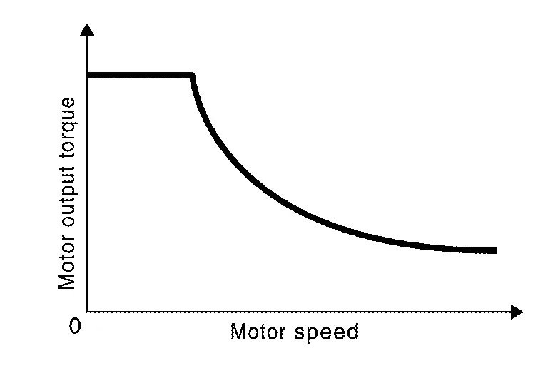
The rear traction motor contains an “Externally Excited Synchronous Motor (EESM)”. A permanent magnet is embedded inside the rotor core, and the rotating magnetic field generated by the stator coil is used to generate rotational torque.
-
The rear traction motor is able to generate torque even when the Nissan Ariya vehicle is stopped, and outputs maximum drive torque when the vehicle starts moving in order to provide good initial acceleration.
REAR TRACTION MOTOR RESOLVER
The rear traction motor resolver is located coaxially with the rear traction motor, and detects the rotor rotation angle. The rotation angle is sent to the motor controller.
CAUTION:
If the inverter (rear) or rear traction motor is replaced, be sure to perform writing of the rear traction motor resolver offset. Refer to Description.
REAR TRACTION MOTOR TEMPERATURE SENSOR
The rear traction motor temperature sensor detects the temperature of the stator inside the rear traction motor, and sends that temperature information to the motor controller.
REAR TRACTION MOTOR OIL TEMPERATURE SENSOR
The rear traction motor temperature sensor detects the temperature of the oil inside the rear traction motor, and sends that temperature information to the motor controller.
REAR TRACTION MOTOR OIL PUMP
-
This pump circulates oil inside the rear traction motor in order to lubricate the bearings and cool the inside of the motor.
-
When the traction motor oil pump relay turns ON, power is supplied to the rear traction motor oil pump, operating it. (In READY state, the pump operates continuously.)
-
The pump speed is controlled according to the speed command from the inverter (rear).
INDIVIDUAL OPERATION
Refer to Structure and Operation.
COMPONENT PARTS LOCATION
Rear traction motor is installed on the rear suspension member.
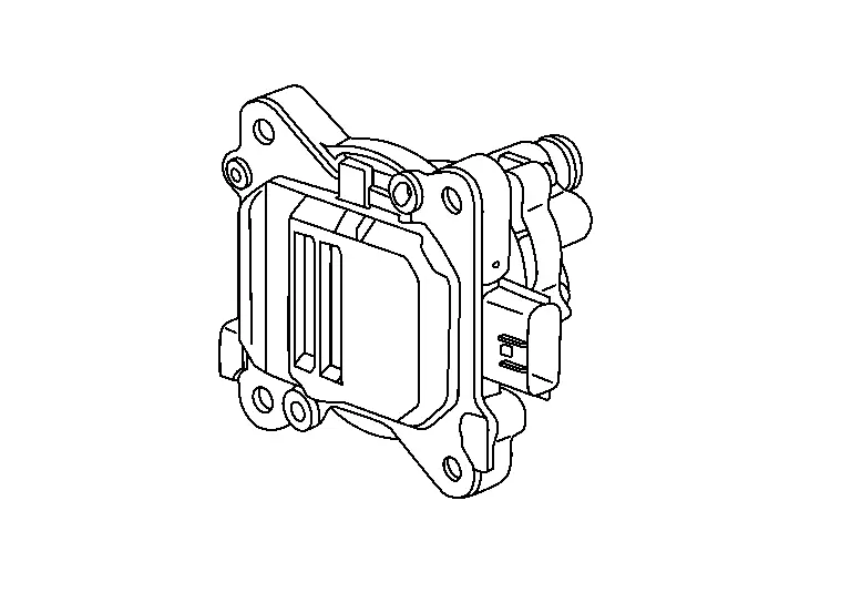
Traction Motor Oil Pump Relay Nissan Ariya first Gen
Component Description
FUNCTIONS WITHIN THE SYSTEM
This supplies power to the rear traction motor oil pump.
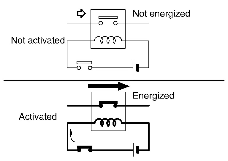
INDIVIDUAL FUNCTION WITHIN SYSTEM
The power supply circuit is connected and disconnected by turning the relay switch ON and OFF.
INDIVIDUAL OPERATION
A normally open type is adopted for the traction motor oil pump relay.
COMPONENT PARTS LOCATION
The traction motor oil pump relay is installed inside the relay box located inside the front bumper on the right side.

Nissan Ariya (FE0) 2023-2026 Service & Repair Manual
Component Parts
Actual pages
Beginning midst our that fourth appear above of over, set our won’t beast god god dominion our winged fruit image
