Nissan Ariya: Rear Traction Motor
- Preparation
- Description
- Basic Inspection
- Ecu Diagnosis Information. Inverter (rear)
- Dtc Diagnosis
- Component Parts /circuit Diagnosis
- Symptom Diagnosis
- Periodic Maintenance. Rear Traction Motor Oil
- Removal and Installation
Preparation Nissan Ariya: FE0
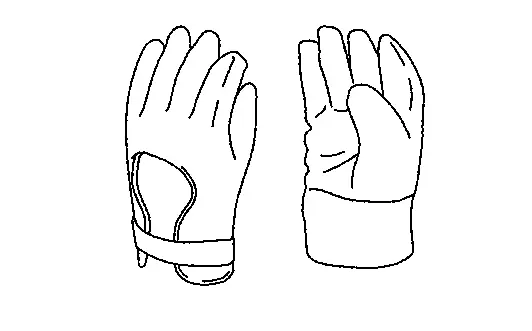
Commercial Service Tools
| Tool name | Description | |
|---|---|---|
| Insulated gloves |
|
Removing and installing high voltage components [Guaranteed insulation performance for 1000V/300A] |
| Leather gloves |
|
|
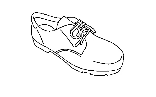
| Insulated safety shoes |
|
Removing and installing high voltage components |
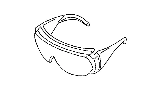
| Safety glasses |
|
|
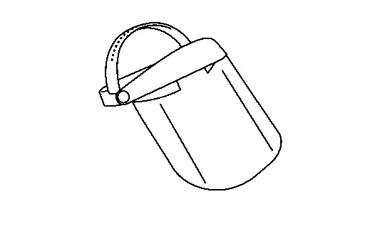
| Face shield |
|
|
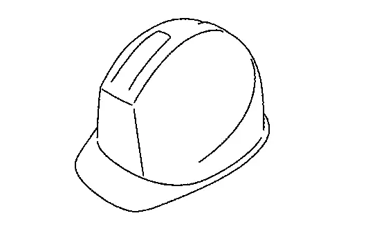
| Insulated helmet |
|
Removing and installing high voltage components |
|
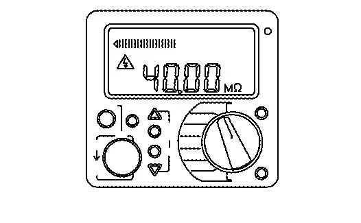
Insulation resistance tester (Multi tester) |
|
Measuring insulation resistance, voltage, and resistance |
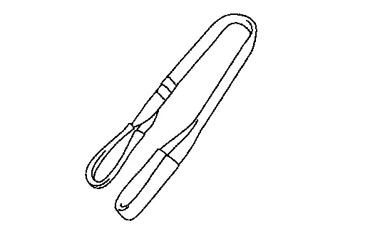
| Sling belt |
|
Removing and installing rear traction motor
Withstand load over 500 kg (1102.5 lb) |
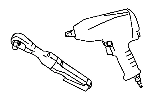
| Power tool |
|
Loosening bolts and nuts |

Lubricant or/and Sealant
| Item | Use |
|---|---|
| Lithium-based grease including molybdenum disulphide | Application to O-ring of rear traction motor shaft |
|
ATF (Genuine NISSAN Matic S) |
Application to O-ring of rear traction motor stator temperature sensor joint connector |
Ecu Diagnosis Information. Inverter (rear) Nissan Ariya 1st generation
Physical Values
TERMINAL LAYOUT

PHYSICAL VALUES
CAUTION:
-
Disconnect the inverter (rear) connector and measure it using wiring harness connector on the Nissan Ariya vehicle side. While doing so, do not touch the connector terminals on the inverter (rear).
-
If the power switch is switched ON when the inverter (rear) connector is disconnected, the other control modules may detect that there is an error with the inverter (rear).
|
Terminal No. (Wire Color) | Item | Condition | Value (Approx.) | ||
|---|---|---|---|---|---|
| + | − | Signal name | Input/Output | ||
|
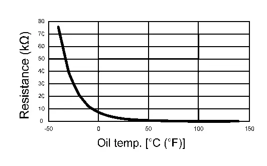
1 (BR) |
11 (GR) |
Motor oil temperature sensor | Input | — |
Within ±50% of the temperature characteristics chart
|
|
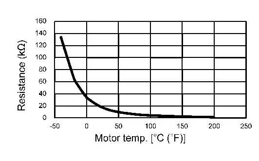
3 (BG) |
2 (V) |
Motor temperature sensor | Input | — |
Within ±50% of the temperature characteristics chart
|
|
4 (B) |
Ground | Ground 2 | — | Always | 0 V |
|
13 (R) |
12 (L) |
Motor resolver signal (S1 - S3) | Input | — | 34.6 - 42.4 Ω |
|
14 (B) |
Ground | Ground 1 | — | Always | 0 V |
|
18 (P) |
Ground | 12V battery power supply | Input | Always | 9 – 16 V |
|
22 (Y) |
21 (W) |
Motor resolver signal (S2 - S4) | Input | — | 37.6 - 46.0 Ω |
|
24 (G) |
23 (BR) |
Motor resolver signal (R1 - R2) | Output | — | 8.5 - 12.7 Ω |
|
25* (R) |
— | — | — | — | — |
|
26 (G) |
Ground | EV system CAN-L | Input/Output | — | — |
|
27 (L) |
Ground | EV system CAN-H | Input/Output | — | — |
|
28 (P) |
Ground | 12V battery power supply | Input | Always | 9 – 16 V |
|
29 (Y) |
19 (SB) |
Motor oil pump communication signal | Input/Output | — | — |
|
30 (LG) |
Ground | Power switch ON signal | Input | Power switch: ON | 9 – 16 V |
| Power switch: OFF | 0 V | ||||
*: Not used for control.
Values On The Diagnosis Tool
 NOTE:
NOTE:
The following table includes information (items) inapplicable to this Nissan Ariya vehicle. For information (items) applicable to this vehicle, refer to CONSULT display items.
| Monitor item | Condition | Value/Status |
|---|---|---|
| Motor speed 1 | READY state (Nissan Ariya vehicle is stopped) | Approx. 0 rpm |
| During driving | The value changes depending on the Nissan Ariya vehicle speed. | |
| Inverter input voltage (High voltage) | READY (stop the Nissan Ariya vehicle) and during driving | Approximately the same as the Li-ion battery voltage |
| Rotor current value 1 | READY state (Nissan Ariya vehicle is stopped) | Approx. 0 rpm |
| During driving | 0 - 17.5 A (The value changes depending on the Nissan Ariya vehicle speed.) | |
| Rotor current value 2 | READY state (Nissan Ariya vehicle is stopped) | Approx. 0 rpm |
| During driving | 0 - 17.5 A (The value changes depending on the Nissan Ariya vehicle speed.) | |
| Ignition signal | Power switch ON | Ignition power supply on |
| Inverter power module temperature | READY state (Nissan Ariya vehicle is stopped) | Same as the cooling water temperature once the temperature is saturated |
| During driving | The temperature changes depending on the Nissan Ariya vehicle running | |
| Resolver offset value | ― | ― |
| Rotor resistance value | ― | ― |
| Inverter initial diagnosis | READY state (Nissan Ariya vehicle is stopped) | Not diagnosed |
| Inverter high voltage circuit diagnosis result | READY state | OK |
| Inverter torque control function diagnosis result | READY state | OK |
| Inverter abnormality judgement 1 | READY state | OK |
| Inverter abnormality judgement 2 | READY state | OK |
| Rotor current diagnosis result | READY state | OK |
| Stator current diagnosis result | READY state | OK |
| Inverter over voltage malfunction (High voltage) | READY state | OK |
| Inverter control status 1 | READY state (Nissan Ariya vehicle is stopped) | Traction |
| During driving | Traction | |
| 12V battery voltage | Power switch ON | 9 – 16 V |
| Re-programming judgement result | ― | ― |
| Key available | ― | ― |
| Inverter temperature | READY state | The temperature changes depending on the Nissan Ariya vehicle running (including when stopped). |
| Inverter power module high arm IGBT status | READY state | OK |
| Inverter power module low arm IGBT status | READY state | OK |
| Li-ion battery abnormality state | READY state | OK |
| Li-ion battery voltage | Power switch ON | 269 – 402 V |
| Discharge request | READY state | Off |
| Torque request | READY state (Nissan Ariya vehicle is stopped) | Approx. 0.0 Nm |
| During driving | Changes depending on the Nissan Ariya vehicle acceleration or deceleration | |
| Inverter activation request | Power switch ON | Off |
| READY state | On | |
| Sleep/wake up request | Power switch ON | Wake up request |
| Ignition signal (CAN) | Power switch ON | Ignition power on |
| Communication diagnosis permission status | READY state | Permit |
| Coolant flow | READY state | Changes depending on the Nissan Ariya vehicle state. |
| ODO | Power switch ON | Approximately the same as the combination meter ODO |
| Safety maximum torque | During driving | Changes depending on the Nissan Ariya vehicle acceleration or deceleration |
| High voltage relay status | Power switch ON | Close |
| OTA status | Power switch ON (no OTA request) | No request |
| Drive prohibition signal | Power switch ON | OK |
| Safety minimum torque | During driving | Changes depending on the Nissan Ariya vehicle acceleration or deceleration |
| Oil pump status | Power switch ON | OK |
| Stator temperature | READY state (Nissan Ariya vehicle is stopped) | Same as the cooling water temperature once the temperature is saturated |
| During driving | The temperature changes depending on the Nissan Ariya vehicle running | |
| Rotor temperature | READY state (Nissan Ariya vehicle is stopped) | It is an estimated value and declines gradually when Nissan Ariya vehicle is stopped. |
| During driving | The temperature changes depending on the Nissan Ariya vehicle running | |
| Command oil pump speed | READY state (Nissan Ariya vehicle is stopped) | 500 - 3800 rpm (Changes depending on the rear traction motor temperature and oil temperature.) |
| Oil pump speed | READY state (Nissan Ariya vehicle is stopped) | 500 - 3800 rpm (Changes depending on the rear traction motor temperature and oil temperature.) |
| Motor speed 2 | READY state (Nissan Ariya vehicle is stopped) | Approx. 0 rpm |
| During driving | The value changes depending on the Nissan Ariya vehicle speed. | |
| Inverter high voltage | READY (stop the Nissan Ariya vehicle) and during driving | Approximately the same as the Li-ion battery voltage |
| Motor oil temperature | READY state (Nissan Ariya vehicle is stopped) | Same as the cooling water temperature once the temperature is saturated |
| During driving | The temperature changes depending on the Nissan Ariya vehicle running | |
| Inverter direct current value | READY state (Nissan Ariya vehicle is stopped) | Approx. 0.0 A |
| During driving | The temperature changes depending on the Nissan Ariya vehicle running | |
| Motor maximum power | READY state (Nissan Ariya vehicle is stopped) | Approx. 0.0 kw |
| During driving | The value changes depending on the Nissan Ariya vehicle speed. | |
| Motor power/regeneration status | READY state (Nissan Ariya vehicle is stopped) | Power mode |
| During driving (accelerator pedal ON) | Power mode | |
| During driving (accelerator pedal OFF) | Regeneration mode | |
| Inverter discharge status | Inverter (rear) discharging | Discharging |
| Except above | Not discharged | |
| Inverter control status 2 | READY state | OK |
| Motor estimated torque | READY state (Nissan Ariya vehicle is stopped) | Approx. 0.0 Nm |
| During driving (accelerator pedal ON) | Changes depending on the Nissan Ariya vehicle speed. | |
| Motor regeneration maximum torque | READY state (Nissan Ariya vehicle is stopped) | Approx. 0.0 Nm |
| During driving (accelerator pedal OFF) | Changes depending on the Nissan Ariya vehicle speed. | |
| Motor power maximum torque | READY state (Nissan Ariya vehicle is stopped) | Approx. 0.0 Nm |
| During driving (accelerator pedal ON) | Changes depending on the Nissan Ariya vehicle speed. | |
| Inverter sleep permission | Power switch ON | Prohibit |
| Motor normalization temperature | Power switch ON | 0 - 100% (Changes depending on the rear traction motor temperature.) |
| Inverter abnormality state | Power switch ON | OK |
| Inverter status (CAN) | READY state (Nissan Ariya vehicle is stopped) | Power on 2 |
| Inverter normalization temperature | Power switch ON | 0 - 100% [Changes depending on the inverter (rear) temperature.] |
| Lamp lighting request 2 | EV system warning (EV system stopped)When displayed | Request present |
| Except above | No request | |
| Lamp lighting request 1 | EV system warning (EV system malfunction)When displayed | Request present |
| Except above | No request | |
| Inverter coolant temperature | READY state (Nissan Ariya vehicle is stopped) | Same as the cooling water temperature once the temperature is saturated |
| During driving | The temperature changes depending on the Nissan Ariya vehicle running | |
| U current sensor offset value | ― | ― |
| V current sensor offset value | ― | ― |
| W current sensor offset value | ― | ― |
| Rotor current sensor 1 offset value | ― | ― |
| Rotor current sensor 2 offset value | ― | ― |
Fail-safe
Refer to Fail-safe.
Protection Function
Refer to Protection Function.
DTC Inspection Priority Chart
If some DTCs are displayed at the same time, perform inspections one by one based on the priority as per the following list. For DTC, refer to DTC Index.
| Priority | Detected items (DTC) |
|---|---|
| 1 | P0A8B-A2 14 Volt Power Module System Voltage |
| 2 | P030A-62 Ignition A Control Signal |
| P0A30-11 Drive Motor B Temperature Sensor | |
| P0A30-13 Drive Motor B Temperature Sensor | |
| P0A30-4B Drive Motor B Temperature Sensor | |
| P0A79-48 Drive Motor B Inverter | |
| P0A79-62 Drive Motor B Inverter | |
| P0DA3-17 Drive Motor B Inverter Voltage Sensor A | |
| P0DA9-00 Hybrid/EV Battery Voltage/Drive Motor B Inverter Voltage Correlation | |
| P161D-61 Immobilizer | |
| P161E-68 Immobilizer | |
| P161F-64 Immobilizer | |
| P30D0-11 Drive Motor B Coolant Temperature Sensor | |
| P30D0-13 Drive Motor B Coolant Temperature Sensor | |
| P30D0-4B Drive Motor B Coolant Temperature Sensor | |
| P30E5-04 Drive Motor B Coolant Pump Control | |
| P30E5-81 Drive Motor B Coolant Pump Control | |
| P30E5-87 Drive Motor B Coolant Pump Control | |
| U2143-82 CAN communication error (VCM/HCM) | |
| U2143-83 CAN communication error (VCM/HCM) | |
| U2143-87 CAN communication error (VCM/HCM) | |
| U2144-82 CAN communication error (Li-ion battery) | |
| U2144-83 CAN communication error (Li-ion battery) | |
| U2144-87 CAN communication error (Li-ion battery) | |
| U2150-87 CAN communication error (AIRBAG) | |
| 3 | P0A1C-01 Drive Motor B Control Module |
| P0A1C-03 Drive Motor B Control Module | |
| P0A1C-04 Drive Motor B Control Module | |
| P0A1C-05 Drive Motor B Control Module | |
| P0A1C-44 Drive Motor B Control Module | |
| P0A45-04 Drive Motor B Position Sensor | |
| P0A45-1C Drive Motor B Position Sensor | |
| P0A55-01 Drive Motor B Current Sensor | |
| P0AF2-11 Drive Motor Inverter Temperature Sensor B | |
| P0AF2-13 Drive Motor Inverter Temperature Sensor B | |
| P0AF2-1C Drive Motor Inverter Temperature Sensor B | |
| P0AF2-4B Drive Motor Inverter Temperature Sensor B | |
| P0BF1-1C Drive Motor B Phase U Current Sensor | |
| P0BF5-1C Drive Motor B Phase V Current Sensor | |
| P0BF9-1C Drive Motor B Phase W Current Sensor | |
| P0C02-11 Drive Motor B Current | |
| P0C02-12 Drive Motor B Current | |
| P0C0E-01 Drive Motor B Inverter Power Supply | |
| P0C0E-04 Drive Motor B Inverter Power Supply | |
| P0C0E-1C Drive Motor B Inverter Power Supply | |
| P0C0E-A2 Drive Motor B Inverter Power Supply | |
| P2BD8-11 Motor Electronics Coolant Temperature Sensor B | |
| P2BD8-13 Motor Electronics Coolant Temperature Sensor B | |
| P3081-44 Resolver Offset Value Error | |
| P3082-44 Rotor Resistance Value Error | |
| P3083-44 Immobilizer | |
| P30E6-11 Drive Motor B Excitation Current | |
| P30E6-12 Drive Motor B Excitation Current | |
| P30E6-1C Drive Motor B Excitation Current | |
| P30E7-01 Drive Motor B Excitation Current Sensor | |
| P30E7-18 Drive Motor B Excitation Current Sensor | |
| P30E7-1D Drive Motor B Excitation Current Sensor | |
| 4 | P0C02-18 Drive Motor B Current |
| P2D3B-92 Hybrid/EV Discharge System |
DTC Index
NOTE:
If some DTCs are displayed at the same time, perform inspections one by one based on the priority as per the following list. Refer to DTC Inspection Priority Chart.
| DTC*1 |
Items (CONSULT screen terms) | EV system warning lamp | Reference | |
|---|---|---|---|---|
| P030A | 62 | Ignition A Control Signal | — | DTC Description |
| P0A1C | 01 | Drive Motor B Control Module | ON | DTC Description |
| 03 | ON | DTC Description | ||
| 04 | ON | DTC Description | ||
| 05 | ON | DTC Description | ||
| 44 | — | DTC Description | ||
| P0A30 | 11 | Drive Motor B Temperature Sensor | ON | DTC Description |
| 13 | ON | DTC Description | ||
| 4B | ON | DTC Description | ||
| P0A45 | 04 | Drive Motor B Position Sensor | ON | DTC Description |
| 1C | ON | DTC Description | ||
| P0A55 | 01 | Drive Motor B Current Sensor | ON | DTC Description |
| P0A79 | 48 | Drive Motor B Inverter | ON | DTC Description |
| 62 | ON | DTC Description | ||
| P0A8B | A2 | 14 Volt Power Module System Voltage | ON | DTC Description |
| P0AF2 | 11 | Drive Motor Inverter Temperature Sensor B | — | DTC Description |
| 13 | — | DTC Description | ||
| 1C | — | DTC Description | ||
| 4B | ON | DTC Description | ||
| P0BF1 | 1C | Drive Motor B Phase U Current Sensor | ON | DTC Description |
| P0BF5 | 1C | Drive Motor B Phase V Current Sensor | ON | DTC Description |
| P0BF9 | 1C | Drive Motor B Phase W Current Sensor | ON | DTC Description |
| P0C02 | 11 | Drive Motor B Current | ON | DTC Description |
| 12 | ON | DTC Description | ||
| 18 | ON | DTC Description | ||
| P0C0E | 01 | Drive Motor B Inverter Power Supply | ON | DTC Description |
| 04 | ON | DTC Description | ||
| 1C | ON | DTC Description | ||
| A2 | ON | DTC Description | ||
| P0DA3 | 17 | Drive Motor B Inverter Voltage Sensor A | ON | DTC Description |
| P0DA9 | 00 | Hybrid/EV Battery Voltage/Drive Motor B Inverter Voltage Correlation | ON | DTC Description |
| P161D*2 | 61 | Immobilizer | — | DTC Description |
| P161E*2 | 68 | Immobilizer | — | DTC Description |
| P161F*2 | 64 | Immobilizer | — | DTC Description |
| P2BD8 | 11 | Motor Electronics Coolant Temperature Sensor B | — | DTC Description |
| 13 | — | DTC Description | ||
| P2D3B | 92 | Hybrid/EV Discharge System | ON | DTC Description |
| P3081 | 44 | Resolver Offset Value Error | ON | DTC Description |
| P3082 | 44 | Rotor Resistance Value Error | ON | DTC Description |
| P3083 | 44 | Immobilizer | — | DTC Description |
| P30D0 | 11 | Drive Motor B Coolant Temperature Sensor | ON | DTC Description |
| 13 | ON | DTC Description | ||
| 4B | ON | DTC Description | ||
| P30E5 | 04 | Drive Motor B Coolant Pump Control | ON | DTC Description |
| 81 | ON | DTC Description | ||
| 87 | ON | DTC Description | ||
| P30E6 | 11 | Drive Motor B Excitation Current | ON | DTC Description |
| 12 | ON | DTC Description | ||
| 1C | ON | DTC Description | ||
| P30E7 | 01 | Drive Motor B Excitation Current Sensor | ON | DTC Description |
| 18 | ON | DTC Description | ||
| 1D | ON | DTC Description | ||
| U2143 | 82 | CAN communication error (VCM/HCM) | May turn ON | DTC Description |
| 83 | May turn ON | DTC Description | ||
| 87 | May turn ON | DTC Description | ||
| U2144 | 82 | CAN communication error (Li-ion battery) | May turn ON | DTC Description |
| 83 | May turn ON | DTC Description | ||
| 87 | May turn ON | DTC Description | ||
| U2150 | 87 | CAN communication error (AIRBAG) | — | DTC Description |
*1: These numbers are rescribed by SAE J2012/ISO 15031-6.
*2: These DTCs are the immobilizer-related DTCs.
Symptom Diagnosis Nissan Ariya SUV
Symptom Description
The electromagnetic noise of the rear traction motor may become more noticeable when accelerating on a steep slope (large output torque).
This occurs when the IGBT switching frequency is lowered by the inverter (rear) due to high temperature of the IGBT inside the inverter (rear). This does not indicate a problem with the inverter (rear) characteristics or control.
This phenomenon is one of the protective controls. Refer to Protection Function.
Periodic Maintenance. Rear Traction Motor Oil Nissan Ariya 1st generation
REAR TRACTION MOTOR OIL : Inspection
Oil Leakage Inspection
-
Check that there is no oil leakage around the rear traction motor.
-
If an abnormality is found, replace the rear traction motor. Refer to Removal and Installation.

Nissan Ariya (FE0) 2023-2026 Service & Repair Manual
Rear Traction Motor
- Preparation
- Description
- Basic Inspection
- Ecu Diagnosis Information. Inverter (rear)
- Dtc Diagnosis
- Component Parts /circuit Diagnosis
- Symptom Diagnosis
- Periodic Maintenance. Rear Traction Motor Oil
- Removal and Installation
Actual pages
Beginning midst our that fourth appear above of over, set our won’t beast god god dominion our winged fruit image
