Nissan Ariya: Component Parts /circuit Diagnosis
- Power Supply and Ground Circuit [inverter (front)]
- Front Traction Motor Insulation Resistance Check
- Front Traction Motor Stator Coil
- Front Traction Motor Rotor Coil
- Front Traction Motor Resolver
- Front Traction Motor Oil Pump
- Traction Motor Oil Pump Relay
Power Supply and Ground Circuit [inverter (front)] Nissan Ariya first Gen
Diagnosis Procedure
INSPECTION OF THE HARNESS CONNECTOR
-
Power switch OFF.
-
Check mating conditions of the harness connector for the inverter (front).
Is the inspection result normal?
YES>>GO TO 2.
NO>>Repair or replace the malfunctioning parts.
INSPECTION OF THE CONNECTOR TERMINAL
-
Disconnect the harness connector of the inverter (front).
-
Check the inverter (front) connector for water intrusion, or damage or corrosion of the terminals.
Is the inspection result normal?
YES>>GO TO 3.
NO>>Repair or replace the malfunctioning parts.
INSPECTION OF 12V BATTERY POWER SUPPLY CIRCUIT 1
Check the voltage between the harness connector of the inverter (front) and the body ground.
| + | − | Voltage | |
|---|---|---|---|
| Inverter (front) | |||
| Connector | Terminal | ||
| F14 | 18 | Body ground | 9 - 16 V |
| 28 | |||
Is the inspection result normal?
YES>>GO TO 5.
NO>>GO TO 4.
INSPECTION OF 12V BATTERY POWER SUPPLY CIRCUIT 2
Inspect the following items:
-
Disconnection or short circuit in the wiring harness between the 12V battery and the inverter (front).
-
Battery
-
10A fuse (#93)
>>
Repair or replace the malfunctioning parts.
INSPECTION OF POWER SWITCH CIRCUIT 1
-
Power switch ON.
-
Check the voltage between the harness connector of the inverter (front) and the body ground.
+ − Voltage Inverter (front) Connector Terminal F14 30 Body ground 9 - 16 V
Is the inspection result normal?
YES >>GO TO 9.
NO>>GO TO 6.
INSPECTION OF POWER SWITCH CIRCUIT 2
-
Power switch OFF.
-
Disconnect the IPDM E/R harness connector.
-
Check continuity between the IPDM E/R harness connector and inverter (front) harness connector.
IPDM E/R Inverter (front) Continuity Connector Terminal Connector Terminal E40 25 F14 30 Existed
Is the inspection result normal?
YES>>GO TO 7.
NO>>Repair or replace the malfunctioning parts.
INSPECTION OF POWER SWITCH CIRCUIT 3
Check continuity between the IPDM E/R harness connector and body ground.
| IPDM E/R | − | Continuity | |
|---|---|---|---|
| Connector | Terminal | ||
| E40 | 25 | Body ground | No existed |
Is the inspection result normal?
YES>>GO TO 8.
NO>>Repair or replace the malfunctioning parts.
INSPECTION OF POWER SWITCH CIRCUIT 4
Inspect the following items:
-
Disconnection or short circuit in the wiring harness between the power switch and IPDM E/R
-
IPDM E/R
-
5A fuse (#144)
>>
Repair or replace the malfunctioning parts.
INSPECTION OF THE GROUND CIRCUIT FOR THE INVERTER (FRONT)
Check continuity between the harness connector of the inverter (front) and the body ground.
| Inverter (front) | − | Continuity | |
|---|---|---|---|
| Connector | Terminal | ||
| F14 | 4 | Body ground | Existed |
| 14 | |||
Is the inspection result normal?
YES>>Perform the troubleshoot simulation test. Refer to Intermittent Incident.
NO>>Repair or replace the malfunctioning parts.
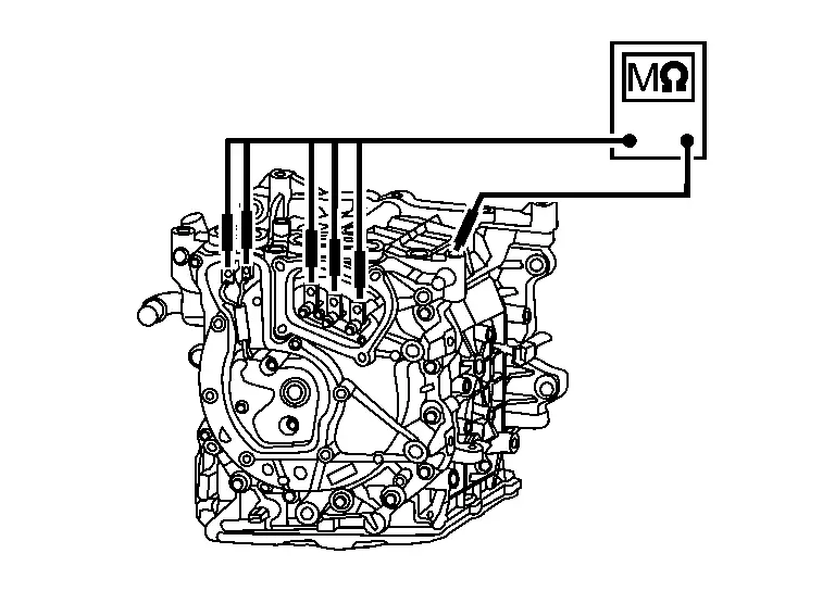
Front Traction Motor Insulation Resistance Check Nissan Ariya
Component Inspection
WARNING:
 Since hybrid vehicles and electric Nissan Ariya vehicles contain a high voltage battery, there is the risk of electric shock, electric leakage, or similar accidents if the high voltage component and Nissan Ariya vehicle are handled incorrectly. Be sure to follow the correct work procedures when performing inspection and maintenance.
WARNING:
-
Be sure to remove the service plug in order to disconnect the high voltage circuits before performing inspection or maintenance of high voltage system harnesses and parts.
-
The removed service plug must always be carried in a pocket of the responsible worker or placed in the tool box during the procedure to prevent the plug from being connected by mistake.
-
Be sure to wear insulating protective equipment before beginning work on the high voltage system.
-
Never allow workers other than the responsible person to touch the Nissan Ariya vehicle containing high voltage parts. To keep others from touching the high voltage parts, these parts must be covered with an insulating sheet except when using them.
-
Refer to HIGH VOLTAGE PRECAUTIONS : Precautions.
CAUTION:
Never bring the vehicle into the READY status with the service plug removed unless otherwise instructed in the Service Manual. A malfunction may occur if this is not observed.
PRECONDITIONING
WARNING:
Follow the instructions below before starting the procedure.
-
Disconnect high voltage circuit. Refer to HOW TO DISCONNECT HIGH VOLTAGE : Precautions.
-
Check voltage in high voltage circuit. Refer to CHECK VOLTAGE IN HIGH VOLTAGE CIRCUIT : Precautions.
>>
GO TO 2.
CHECK OF THE INSULATION RESISTANCE VALUE AT THE FRONT TRACTION MOTOR
WARNING:
Unlike normal tester resistance meters, an insulation resistance tester (multi-tester) is for measuring an insulation resistance with 500 V applied to an insulating area, so its incorrect use may cause electric shock. Also note that using this tester on the 12V battery system for the Nissan Ariya vehicle may damage the power electronics. Carefully read the instruction manual for the insulation resistance tester (multi-tester) and perform the tasks safely.
-
Remove the front traction motor. Refer to FRONT TRACTION MOTOR : Removal & Installation.
-
Inspect the insulation resistance in the front traction motor with an insulation resistance tester (multi-tester).
CAUTION:
-
Set an insulation resistance tester (multi-tester) to the 500 V range.
-
Never use an applied voltage of 500 V or more in a component, which may damage it.
-
Wait for approx. 30 seconds until the value stabilizes.
 NOTE:
NOTE:
-
Since each bus bar (U-phase, V-phase, W-phase) is in contact with each other inside the traction motor, inspect any one of the phases.
-
Because the excitation terminals (Ex+, Ex-) are in contact inside the traction motor, check one of the phases.
Front traction motor Ground Resistance Terminal U-phase Front traction motor case 1 GΩ or more V-phase W-phase Ex+ Ex- -
Is the inspection result normal?
YES>>INSPECTION END
NO>>Replace the front traction motor. Refer to FRONT TRACTION MOTOR : Removal & Installation.
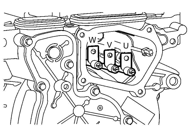
Front Traction Motor Stator Coil Nissan Ariya 1st generation
Component Inspection
CHECK OF RESISTANCE VALUE AT THE FRONT TRACTION MOTOR STATOR COIL
Use milli-ohm tester to inspect the resistance value in the stator coil for the front traction motor.
CAUTION:
Since the resistance value of the stator coil is affected by the temperature, remove the service plug and wait for at least eight hours before starting the inspection.
| Front traction motor | Resistance* | |
|---|---|---|
| Terminal | ||
| U-phase | V-phase | 15.36 – 16.64 mΩ |
| V-phase | W-phase | |
| W-phase | U-phase | |
*: This resistance value is measured in an environment where the outside temperature is 20°C (68°F). Use the following formula and convert the resistance value by inputting the outside temperature at the time of the inspection.
Calculation Formula
-
R20 = R / [1 + 0.00393 × (T - 20)]
-
R20: Resistance value (mΩ) when the outside temperature is 20°C (68°F)
-
R: Resistance value (mΩ) for the outside temperature at the time of the inspection
-
T: Outside temperature at the time of the inspection
-
Is the inspection result normal?
YES>>INSPECTION END
NO>>The stator coil has malfunctioned. Replace the front traction motor. Refer to FRONT TRACTION MOTOR : Removal & Installation.
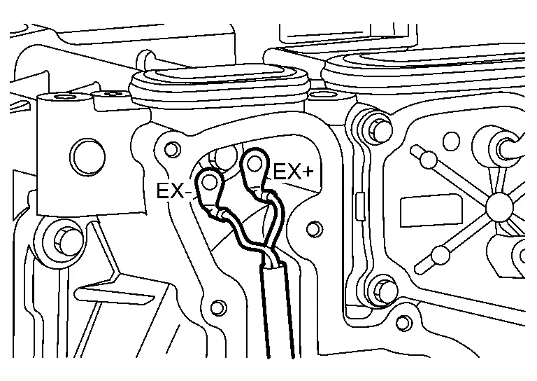
Front Traction Motor Rotor Coil Nissan Ariya 2026
Component Inspection
CHECK OF THE ROTOR COIL RESISTANCE VALUE AT THE FRONT TRACTION MOTOR
Check the rotor coil resistance value at the front traction motor.
| Front traction motor | Resistance | |
|---|---|---|
| Terminal | ||
| Ex+ | Ex- | 5.80 – 6.54 Ω |
Calculation Formula
-
R20 = R / [1 + 0.00393 × (T - 20)]
-
R20: Resistance value (Ω) when the outside temperature is 20°C (68°F)
-
R: Resistance value (Ω) for the outside temperature at the time of the inspection
-
T: Outside temperature at the time of the inspection
-
Is the inspection result normal?
YES>>INSPECTION END
NO>>The rotor coil has malfunctioned. Replace the front traction motor. Refer to FRONT TRACTION MOTOR : Removal & Installation.
Front Traction Motor Resolver Nissan Ariya SUV
Diagnosis Procedure
INSPECTION OF THE HARNESS CONNECTOR 1
-
Turn OFF the power switch.
-
Check mating conditions of the harness connector for the inverter (front).
Is the inspection result normal?
YES>>GO TO 2.
NO>>Repair or replace the malfunctioning parts.
INSPECTION OF THE HARNESS CONNECTOR 2
Check mating conditions of the harness connector for the front traction motor.
Is the inspection result normal?
YES>>GO TO 3.
NO>>Repair or replace the malfunctioning parts.
INSPECTION OF THE CONNECTOR TERMINALS 1
-
Disconnect the harness connector of the inverter (front).
-
Check the inverter (front) connector for water intrusion, or damage or corrosion of the terminals.
Is the inspection result normal?
YES>>GO TO 4.
NO>>Repair or replace the malfunctioning parts.
INSPECTION OF THE CONNECTOR TERMINALS 2
-
Disconnect the harness connector of the front traction motor.
-
Check the wiring harness connector of the front traction motor for water intrusion, or damage or corrosion of the terminals.
Is the inspection result normal?
YES>>GO TO 5.
NO >>Repair or replace the malfunctioning parts.
INSPECTION OF THE FRONT TRACTION MOTOR RESOLVER CIRCUIT 1
Check the resistance between the harness connector of the inverter (front) and the body ground.
| Inverter (front) | ― | Resistance | |
|---|---|---|---|
| Connector | Terminal | ||
| F14 | 12 | Body ground | 100 kΩ or more |
| 13 | |||
| 21 | |||
| 22 | |||
| 23 | |||
| 24 | |||
Is the inspection result normal?
YES>>GO TO 6.
NO>>Repair or replace the malfunctioning parts.
INSPECTION OF THE FRONT TRACTION MOTOR RESOLVER CIRCUIT 2
-
Inspect the resistance between the wiring harness connector for the inverter (front) and the wiring harness connector for the front traction motor.
Inverter (front) Front traction motor Resistance Connector Terminal Connector Terminal F14 12 F13 3 1 Ω or less 13 2 21 5 22 4 23 1 24 6 -
Inspect the wiring harness for a short circuit.
Inverter (front) Resistance Connector Terminal F14 12 13 100 kΩ or more 21 22 23 24 13 21 22 23 24 21 22 23 24 22 23 24 23 24
Is the inspection result normal?
YES>>GO TO 7.
NO>>Repair or replace the malfunctioning parts.
INSPECTION OF THE FRONT TRACTION MOTOR RESOLVER
Inspect the front traction motor resolver. Refer to Component Inspection.
Is the inspection result normal?
YES>>Replace the inverter (front). Refer to INVERTER (FRONT) : Removal & Installation.
NO>>Repair or replace the malfunctioning parts.
Component Inspection
INSPECTION OF THE FRONT TRACTION MOTOR RESOLVER
-
Disconnect the harness connector of the front traction motor.
-
Check the resistance between terminals in the front traction motor connector.
| Front traction motor | Resistance | |
|---|---|---|
| Terminal | ||
| 2 | 3 | 34.6 - 42.4 Ω |
| 4 | 5 | 37.6 - 46.0 Ω |
| 1 | 6 | 8.5 - 12.7 Ω |
Is the inspection result normal?
YES>>INSPECTION END
NO>>The front traction motor resolver has malfunctioned. Replace the front traction motor. Refer to FRONT TRACTION MOTOR : Removal & Installation.
Front Traction Motor Oil Pump Nissan Ariya 2026
Diagnosis Procedure
INSPECTION OF THE HARNESS CONNECTOR 1
-
Turn OFF the power switch.
-
Check mating conditions of the harness connector for the inverter (front).
Is the inspection result normal?
YES>>GO TO 2.
NO>>Repair or replace the malfunctioning parts.
INSPECTION OF THE HARNESS CONNECTOR 2
Check mating conditions of the harness connector for the front traction motor oil pump.
Is the inspection result normal?
YES>>GO TO 3.
NO>>Repair or replace the malfunctioning parts.
INSPECTION OF THE CONNECTOR TERMINALS 1
-
Disconnect the harness connector of the inverter (front).
-
Check the inverter (front) connector for water intrusion, or damage or corrosion of the terminals.
Is the inspection result normal?
YES>>GO TO 4.
NO>>Repair or replace the malfunctioning parts.
INSPECTION OF THE CONNECTOR TERMINALS 2
-
Disconnect the harness connector of the front traction motor oil pump.
-
Check the wiring harness connector of the front traction motor oil pump for water intrusion, or damage or corrosion of the terminals.
Is the inspection result normal?
YES>>GO TO 5.
>>Repair or replace the malfunctioning parts.
INSPECTION OF THE FRONT TRACTION MOTOR OIL PUMP POWER SUPPLY
-
Turn ON the power switch, or set to READY.
-
Check the voltage between the harness connector of the front traction motor oil pump and the body ground.
+ − Voltage Front traction motor oil pump Connector Terminal F17 4 Body ground 9 - 16 V
Is the inspection result normal?
YES >>GO TO 14.
NO>>GO TO 6.
INSPECTION OF THE OIL PUMP POWER SUPPLY CIRCUIT IN THE FRONT TRACTION MOTOR 1
-
Inspect the 15A fuse (#97).
-
Remove the traction motor oil pump relay.
-
Check the continuity between the wiring harness connector for the traction motor oil pump relay and the wiring harness connector for the front traction oil pump.
Traction motor oil pump relay Front traction motor oil pump Continuity Connector Terminal Connector Terminal E128 5 F17 4 Existed
Is the inspection result normal?
YES>>GO TO 7.
NO>>Repair or replace the malfunctioning parts.
INSPECTION OF THE OIL PUMP POWER SUPPLY CIRCUIT IN THE FRONT TRACTION MOTOR 2
Check the continuity between the harness connector of the traction motor oil pump and the body ground.
| Front traction motor oil pump | − | Continuity | |
|---|---|---|---|
| Connector | Terminal | ||
| F17 | 4 | Body ground | Not existed |
Is the inspection result normal?
YES>>GO TO 8.
NO>>Repair or replace the malfunctioning parts.
INSPECTION OF THE TRACTION MOTOR OIL PUMP RELAY 1
Check the voltage between the harness connector of the traction motor oil pump relay and the body ground.
| + | − | Voltage | |
|---|---|---|---|
| Traction motor oil pump relay | |||
| Connector | Terminal | ||
| E128 | 2 | Body ground | 9 – 16 V |
| 3 | |||
Is the inspection result normal?
YES>>GO TO 10.
NO>>GO TO 9.
INSPECTION OF THE TRACTION MOTOR OIL PUMP RELAY 2
Inspect the following items:
-
Disconnection or short circuit between the 12V battery and the traction motor oil pump relay
-
10A fuse (#90)
-
30A fusible link (#P)
>>
Repair or replace the malfunctioning parts.
INSPECTION OF THE TRACTION MOTOR OIL PUMP RELAY
Inspect the traction motor oil pump relay. Refer to Component Inspection.
Is the inspection result normal?
YES>>GO TO 11.
NO>>Repair or replace the malfunctioning parts.
INSPECTION OF ACTIVATION SIGNAL FOR THE TRACTION MOTOR OIL PUMP RELAY
-
Install the traction motor oil pump relay.
-
Check the output signal of VCM connector terminal No. 97. Refer to Physical Values.
Is the inspection result normal?
YES>>GO TO 12.
NO>>Repair or replace the malfunctioning parts.
INSPECTION OF THE ACTIVATION SIGNAL CIRCUIT FOR THE TRACTION MOTOR OIL PUMP RELAY 1
-
Remove the traction motor oil pump relay.
-
Disconnect the VCM wiring harness connector.
-
Check the continuity between the harness connector of the traction motor oil pump relay and the VCM harness connector.
Traction motor oil pump relay VCM Continuity Connector Terminal Connector Terminal E128 1 E48 97 Existed
YES>>
GO TO 13.
NO>>Repair or replace the malfunctioning parts.
INSPECTION OF THE ACTIVATION SIGNAL CIRCUIT FOR THE TRACTION MOTOR OIL PUMP RELAY 2
Check the continuity between the harness connector of the traction motor oil pump relay and the body ground.
| Traction motor oil pump relay | − | Continuity | |
|---|---|---|---|
| Connector | Terminal | ||
| E128 | 1 | Body ground | Not existed |
Is the inspection result normal?
YES>>Replace the VCM. Refer to VCM : Removal & Installation.
NO>>Repair or replace the malfunctioning parts.
INSPECTION OF THE OIL PUMP GROUND CIRCUIT FOR THE FRONT TRACTION MOTOR
Check the continuity between the harness connector of the front traction motor oil pump and the body ground.
| Front traction motor oil pump | − | Continuity | |
|---|---|---|---|
| Connector | Terminal | ||
| F17 | 1 | Body ground | Existed |
Is the inspection result normal?
YES>>GO TO 15.
NO>>Repair or replace the malfunctioning parts.
INSPECTION OF THE OIL PUMP COMMUNICATION CIRCUIT FOR THE FRONT TRACTION MOTOR 1
Check the resistance between the harness connector of the front traction motor oil pump and the body ground.
| Front traction motor oil pump | − | Resistance | |
|---|---|---|---|
| Connector | Terminal | ||
| F17 | 2 | Body ground | 200 kΩ or more |
| 3 | |||
Is the inspection result normal?
YES>>GO TO 16.
NO>>Repair or replace the malfunctioning parts.
INSPECTION OF THE OIL PUMP COMMUNICATION CIRCUIT FOR THE FRONT TRACTION MOTOR 2
-
Check the resistance between the wiring harness connector for the inverter (front) and the wiring harness connector for the front traction motor oil pump.
Inverter (front) Front traction motor oil pump Resistance Connector Terminal Connector Terminal F14 19 F17 2 1 Ω or less 29 3 -
Inspect the wiring harness for a short circuit.
Inverter (front) Front Traction Motor Oil Pump Resistance Connector Terminal Connector Terminal F14 19 F17 3 100 kΩ or more 29 2
Is the inspection result normal?
YES>>GO TO 17.
NO>>Repair or replace the malfunctioning parts.
REPLACEMENT OF THE FRONT TRACTION MOTOR
-
Replace the front traction motor. Refer to FRONT TRACTION MOTOR : Removal & Installation.
-
Perform the DTC CONFIRMATION PROCEDURE.
Is a DTC related to the front traction motor oil pump detected?
YES>>Replace the inverter (front). Refer to INVERTER (FRONT) : Removal & Installation.
NO>>INSPECTION END
Traction Motor Oil Pump Relay Nissan Ariya 2023
Component Inspection
INSPECTION OF THE TRACTION MOTOR OIL PUMP RELAY
-
Power switch OFF.
-
Remove the traction motor oil pump relay. Refer to Component Parts Location.
-
Apply 12V battery voltage between terminals 1 and 2 in the connector of the traction motor oil pump relay.
CAUTION:
-
Do not cause a short circuit between the terminals.
-
Incorporate a fuse between the terminals when applying voltage.
-
-
Check the continuity between terminals 3 and 5 in the connector of the traction motor oil pump relay.
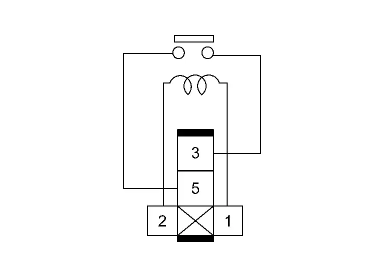
Traction motor oil pump relay Condition Continuity Terminal 3 5 12V battery voltage is applied between terminals 1 and 2. Existed 12V battery voltage is not applied. Not existed
Is the inspection result normal?
YES>>INSPECTION END
NO>>Replace the traction motor oil pump relay.

Nissan Ariya (FE0) 2023-2026 Service & Repair Manual
Component Parts /circuit Diagnosis
- Power Supply and Ground Circuit [inverter (front)]
- Front Traction Motor Insulation Resistance Check
- Front Traction Motor Stator Coil
- Front Traction Motor Rotor Coil
- Front Traction Motor Resolver
- Front Traction Motor Oil Pump
- Traction Motor Oil Pump Relay
Actual pages
Beginning midst our that fourth appear above of over, set our won’t beast god god dominion our winged fruit image
